2002 CHRYSLER CARAVAN transmission oil
[x] Cancel search: transmission oilPage 1851 of 2399
SOLENOID SWITCH VALVE
The solenoid switch valve controls line pressure
from the LR/CC solenoid. In one position, it allows
the low/reverse clutch to be pressurized. In the other,
it directs line pressure to the converter control and
converter clutch valves.
MANUAL VALVE
The manual valve is operated by the mechanical
shift linkage. Its primary responsibility is to send
line pressure to the appropriate hydraulic circuits
and solenoids. The valve has three operating ranges
or positions.
CONVERTER CLUTCH SWITCH VALVE
The main responsibility of the converter clutch switch
valve is to control hydraulic pressure applied to the front
(off) side of the converter clutch piston. Line pressure
from the regulator valve is fed to the torque converter
regulator valve, where it passes through the valve, and is
slightly regulated. The pressure is then directed to the
converter clutch switch valve and to the front side of the
converter clutch piston. This pressure pushes the piston
back and disengages the converter clutch.
CONVERTER CLUTCH CONTROL VALVE
The converter clutch control valve controls the
back (on) side of the torque converter clutch. When
the TCM energizes or modulates the LR/CC solenoid
to apply the converter clutch piston, both the con-
verter clutch control valve and the converter control
valve move, allowing pressure to be applied to the
back side of the clutch.
T/C REGULATOR VALVE
The torque converter regulator valve slightly regu-
lates the flow of fluid to the torque converter.
LOW/REVERSE SWITCH VALVE
The low/reverse clutch is applied from different
sources, depending on whether low (1st) gear or
reverse is selected. The low/reverse switch valve
alternates positions depending on from which direc-
tion fluid pressure is applied. By design, when the
valve is shifted by fluid pressure from one channel,
the opposing channel is blocked. The switch valve
alienates the possibility of a sticking ball check, thus
providing consistent application of the low/reverse
clutch under all operating conditions.
REMOVAL
REMOVAL
NOTE: If valve body is replaced or reconditioned,
the TCM Quick Learn Procedure must be per-formed. (Refer to 8 - ELECTRICAL/ELECTRONIC
CONTROL MODULES/TRANSMISSION CONTROL
MODULE - STANDARD PROCEDURE)
(1) Disconnect battery negative cable.
(2) Disconnect gearshift cable from manual valve
lever.
(3) Remove manual valve lever from manual shaft.
(4) Raise vehicle on hoist.
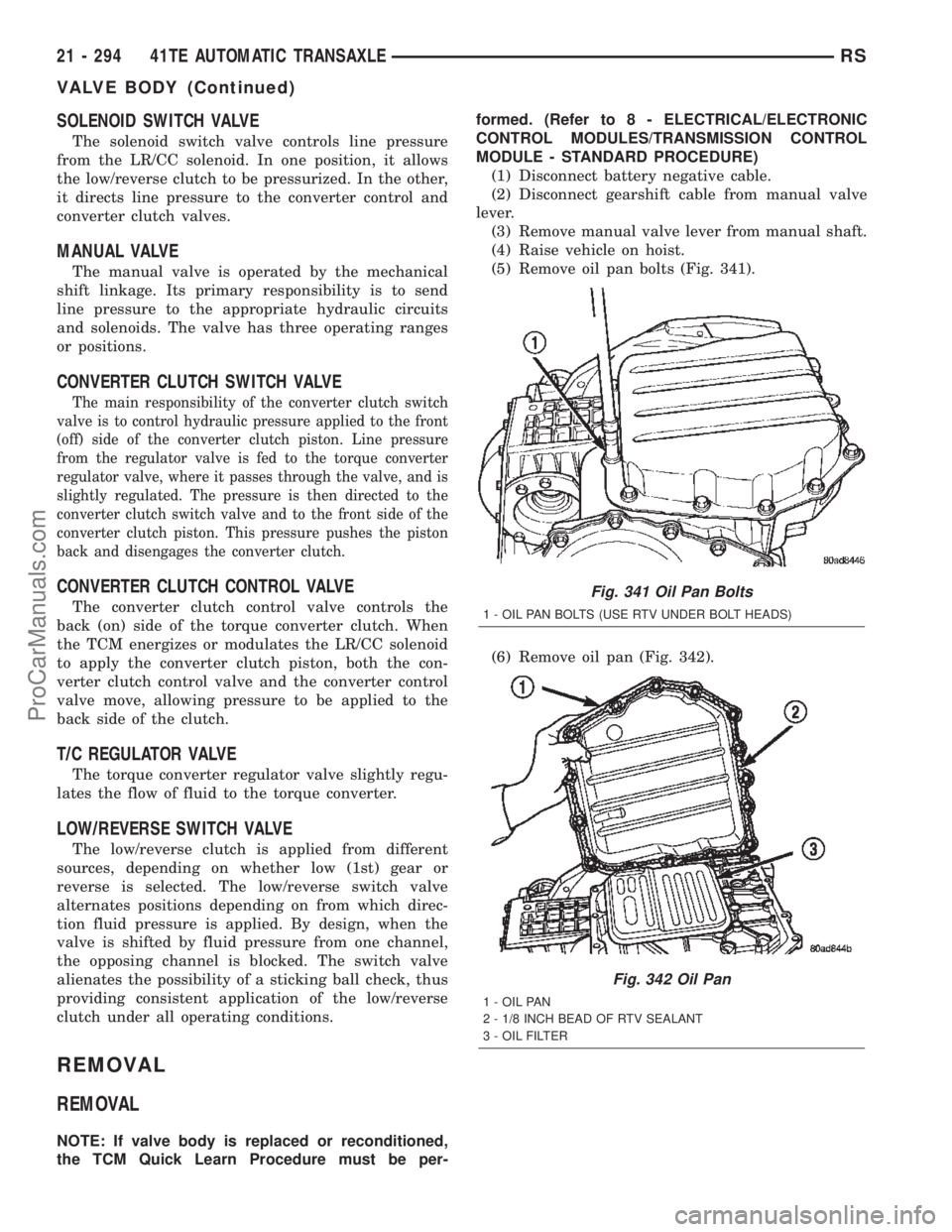
(5) Remove oil pan bolts (Fig. 341).
(6) Remove oil pan (Fig. 342).
Fig. 341 Oil Pan Bolts
1 - OIL PAN BOLTS (USE RTV UNDER BOLT HEADS)
Fig. 342 Oil Pan
1 - OIL PAN
2 - 1/8 INCH BEAD OF RTV SEALANT
3 - OIL FILTER
21 - 294 41TE AUTOMATIC TRANSAXLERS
VALVE BODY (Continued)
ProCarManuals.com
Page 1853 of 2399
REMOVAL
NOTE: If valve body is replaced or reconditioned,
the TCM Quick Learn Procedure must be per-
formed. (Refer to 8 - ELECTRICAL/ELECTRONIC
CONTROL MODULES/TRANSMISSION CONTROL
MODULE - STANDARD PROCEDURE)
(1) Disconnect battery negative cable.
(2) Disconnect gearshift cable from manual valve
lever.
(3) Remove manual valve lever from manual shaft.
(4) Raise vehicle on hoist.
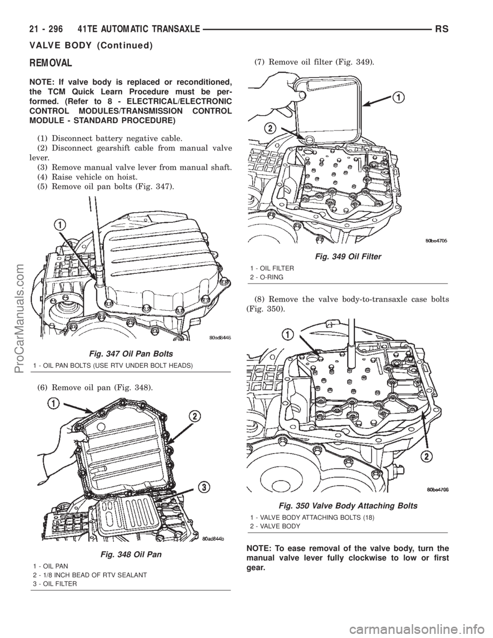
(5) Remove oil pan bolts (Fig. 347).
(6) Remove oil pan (Fig. 348).(7) Remove oil filter (Fig. 349).
(8) Remove the valve body-to-transaxle case bolts
(Fig. 350).
NOTE: To ease removal of the valve body, turn the
manual valve lever fully clockwise to low or first
gear.
Fig. 347 Oil Pan Bolts
1 - OIL PAN BOLTS (USE RTV UNDER BOLT HEADS)
Fig. 348 Oil Pan
1 - OIL PAN
2 - 1/8 INCH BEAD OF RTV SEALANT
3 - OIL FILTER
Fig. 349 Oil Filter
1 - OIL FILTER
2 - O-RING
Fig. 350 Valve Body Attaching Bolts
1 - VALVE BODY ATTACHING BOLTS (18)
2 - VALVE BODY
21 - 296 41TE AUTOMATIC TRANSAXLERS
VALVE BODY (Continued)
ProCarManuals.com
Page 1864 of 2399
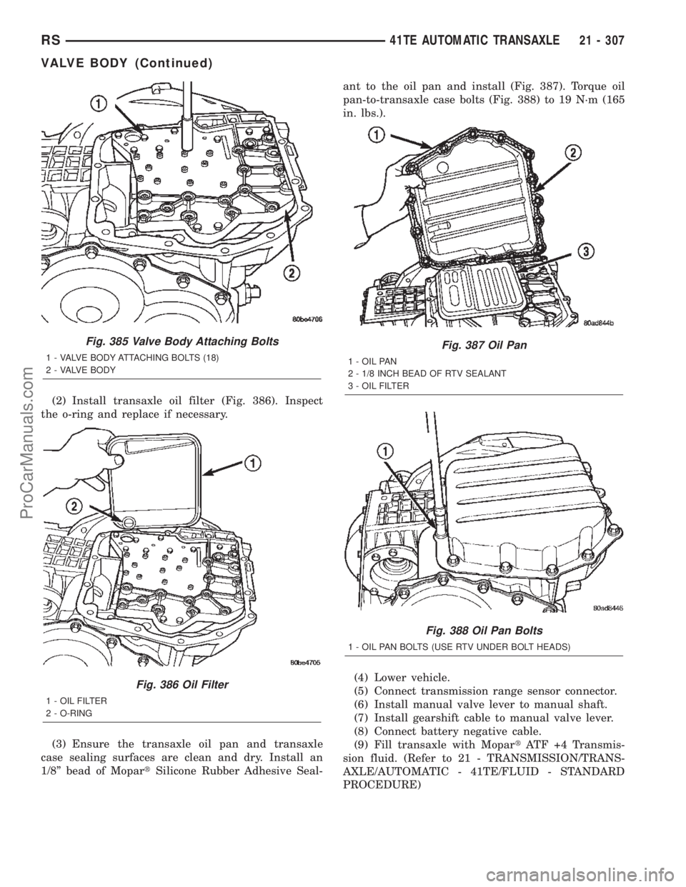
(2) Install transaxle oil filter (Fig. 386). Inspect
the o-ring and replace if necessary.
(3) Ensure the transaxle oil pan and transaxle
case sealing surfaces are clean and dry. Install an
1/8º bead of MopartSilicone Rubber Adhesive Seal-ant to the oil pan and install (Fig. 387). Torque oil
pan-to-transaxle case bolts (Fig. 388) to 19 N´m (165
in. lbs.).
(4) Lower vehicle.
(5) Connect transmission range sensor connector.
(6) Install manual valve lever to manual shaft.
(7) Install gearshift cable to manual valve lever.
(8) Connect battery negative cable.
(9) Fill transaxle with MopartATF +4 Transmis-
sion fluid. (Refer to 21 - TRANSMISSION/TRANS-
AXLE/AUTOMATIC - 41TE/FLUID - STANDARD
PROCEDURE)
Fig. 385 Valve Body Attaching Bolts
1 - VALVE BODY ATTACHING BOLTS (18)
2 - VALVE BODY
Fig. 386 Oil Filter
1 - OIL FILTER
2 - O-RING
Fig. 387 Oil Pan
1 - OIL PAN
2 - 1/8 INCH BEAD OF RTV SEALANT
3 - OIL FILTER
Fig. 388 Oil Pan Bolts
1 - OIL PAN BOLTS (USE RTV UNDER BOLT HEADS)
RS41TE AUTOMATIC TRANSAXLE21 - 307
VALVE BODY (Continued)
ProCarManuals.com
Page 1876 of 2399
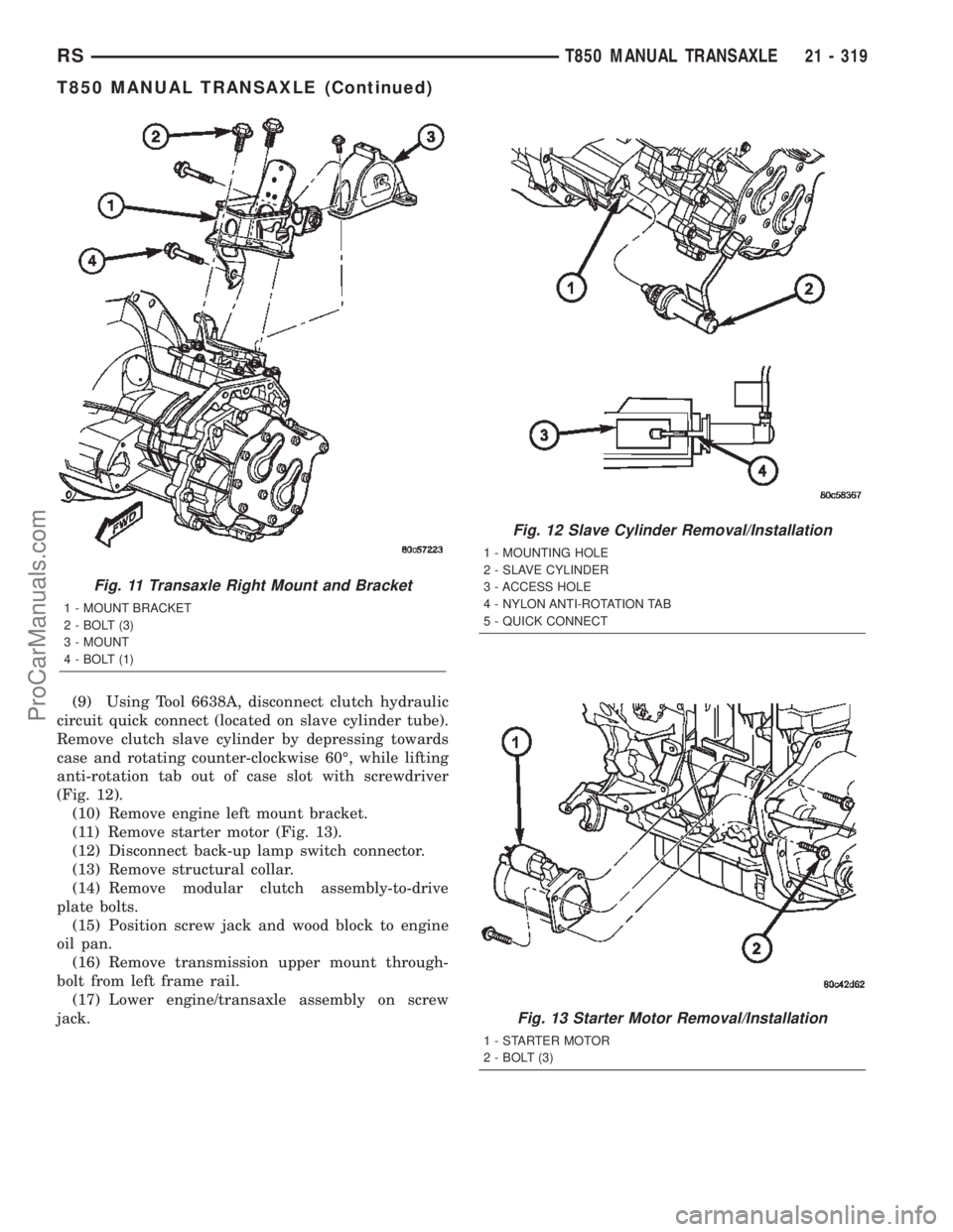
(9) Using Tool 6638A, disconnect clutch hydraulic
circuit quick connect (located on slave cylinder tube).
Remove clutch slave cylinder by depressing towards
case and rotating counter-clockwise 60É, while lifting
anti-rotation tab out of case slot with screwdriver
(Fig. 12).
(10) Remove engine left mount bracket.
(11) Remove starter motor (Fig. 13).
(12) Disconnect back-up lamp switch connector.
(13) Remove structural collar.
(14) Remove modular clutch assembly-to-drive
plate bolts.
(15) Position screw jack and wood block to engine
oil pan.
(16) Remove transmission upper mount through-
bolt from left frame rail.
(17) Lower engine/transaxle assembly on screw
jack.
Fig. 11 Transaxle Right Mount and Bracket
1 - MOUNT BRACKET
2 - BOLT (3)
3 - MOUNT
4 - BOLT (1)
Fig. 12 Slave Cylinder Removal/Installation
1 - MOUNTING HOLE
2 - SLAVE CYLINDER
3 - ACCESS HOLE
4 - NYLON ANTI-ROTATION TAB
5 - QUICK CONNECT
Fig. 13 Starter Motor Removal/Installation
1 - STARTER MOTOR
2 - BOLT (3)
RST850 MANUAL TRANSAXLE21 - 319
T850 MANUAL TRANSAXLE (Continued)
ProCarManuals.com
Page 1879 of 2399
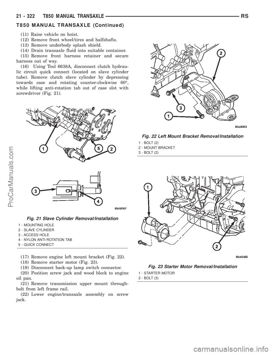
(11) Raise vehicle on hoist.
(12) Remove front wheel/tires and halfshafts.
(13) Remove underbody splash shield.
(14) Drain transaxle fluid into suitable container.
(15) Remove front harness retainer and secure
harness out of way.
(16) Using Tool 6638A, disconnect clutch hydrau-
lic circuit quick connect (located on slave cylinder
tube). Remove clutch slave cylinder by depressing
towards case and rotating counter-clockwise 60É,
while lifting anti-rotation tab out of case slot with
screwdriver (Fig. 21).
(17) Remove engine left mount bracket (Fig. 22).
(18) Remove starter motor (Fig. 23).
(19) Disconnect back-up lamp switch connector.
(20) Position screw jack and wood block to engine
oil pan.
(21) Remove transmission upper mount through-
bolt from left frame rail.
(22) Lower engine/transaxle assembly on screw
jack.
Fig. 21 Slave Cylinder Removal/Installation
1 - MOUNTING HOLE
2 - SLAVE CYLINDER
3 - ACCESS HOLE
4 - NYLON ANTI-ROTATION TAB
5 - QUICK CONNECT
Fig. 22 Left Mount Bracket Removal/Installation
1 - BOLT (2)
2 - MOUNT BRACKET
3 - BOLT (2)
Fig. 23 Starter Motor Removal/Installation
1 - STARTER MOTOR
2 - BOLT (3)
21 - 322 T850 MANUAL TRANSAXLERS
T850 MANUAL TRANSAXLE (Continued)
ProCarManuals.com
Page 1900 of 2399
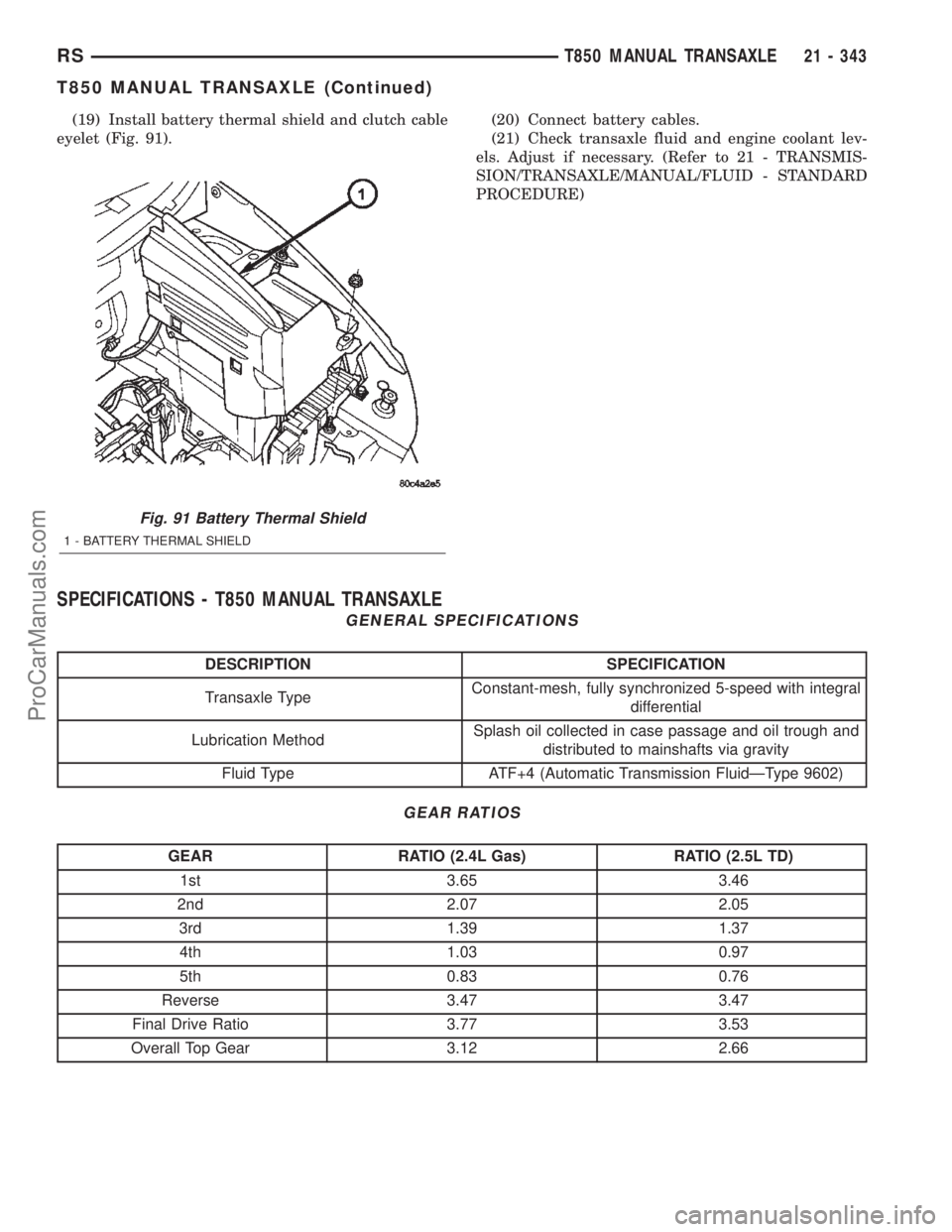
(19) Install battery thermal shield and clutch cable
eyelet (Fig. 91).(20) Connect battery cables.
(21) Check transaxle fluid and engine coolant lev-
els. Adjust if necessary. (Refer to 21 - TRANSMIS-
SION/TRANSAXLE/MANUAL/FLUID - STANDARD
PROCEDURE)
SPECIFICATIONS - T850 MANUAL TRANSAXLE
GENERAL SPECIFICATIONS
DESCRIPTION SPECIFICATION
Transaxle TypeConstant-mesh, fully synchronized 5-speed with integral
differential
Lubrication MethodSplash oil collected in case passage and oil trough and
distributed to mainshafts via gravity
Fluid Type ATF+4 (Automatic Transmission FluidÐType 9602)
GEAR RATIOS
GEAR RATIO (2.4L Gas) RATIO (2.5L TD)
1st 3.65 3.46
2nd 2.07 2.05
3rd 1.39 1.37
4th 1.03 0.97
5th 0.83 0.76
Reverse 3.47 3.47
Final Drive Ratio 3.77 3.53
Overall Top Gear 3.12 2.66
Fig. 91 Battery Thermal Shield
1 - BATTERY THERMAL SHIELD
RST850 MANUAL TRANSAXLE21 - 343
T850 MANUAL TRANSAXLE (Continued)
ProCarManuals.com
Page 2308 of 2399
FRONT/REFRIGERANT - STANDARD PROCE-
DURE - REFRIGERANT SYSTEM CHARGE).
INSTALLATION - COMPRESSOR MOUNTING
BRACKET - 2.4L ENGINE
(1) Position the compressor mounting bracket onto
the engine.
(2) Install and tighten the four screws that secure
the compressor mounting bracket to the engine.
Tighten the screws to 54 N´m (40 ft. lbs.).
(3) Reinstall the compressor onto the mounting
bracket. (Refer to 24 - HEATING & AIR CONDI-
TIONING/PLUMBING/COMPRESSOR - INSTALLA-
TION).
CONDENSER
DESCRIPTION
The condenser is integral to a cooling module
which includes the radiator, the electric cooling fan,
the fan shroud, air seals and an automatic transmis-
sion oil cooler. The cooling module is located in the
air flow in the front of the engine compartment
behind the radiator grille. The condenser cannot be
repaired or adjusted and, if faulty or damaged, it
must be replaced. The condenser may be removed
from the cooling module for service without removing
the cooling module from the vehicle.
OPERATION
The condenser is a heat exchanger that allows the
high-pressure refrigerant gas being discharged by the
compressor to give up its heat to the air passing over
the condenser fins. When the refrigerant gas gives up
its heat, it condenses. When the refrigerant leaves
the condenser, it has become a high-pressure liquid
refrigerant. The volume of air flowing over the con-
denser fins is critical to the proper cooling perfor-
mance of the air conditioning system. Therefore, it is
important that there are no objects placed in front of
the radiator grille openings in the front of the vehicle
or foreign material on the condenser fins that might
obstruct air flow. Also, any factory-installed air seals
or shrouds must be properly reinstalled following
radiator or condenser service.
REMOVAL
WARNING: REFER TO THE APPLICABLE WARN-
INGS AND CAUTIONS FOR THIS SYSTEM BEFORE
PERFORMING THE FOLLOWING OPERATION.
(Refer to 24 - HEATING & AIR CONDITIONING/
PLUMBING - FRONT - WARNING - A/C PLUMBING)
and (Refer to 24 - HEATING & AIR CONDITIONING/
PLUMBING - FRONT - CAUTION - A/C PLUMBING).NOTE: Before removing the condenser, note the
location of each of the radiator and condenser air
seals. These air seals are used to direct air through
the condenser and radiator. The air seals must be
reinstalled in their proper locations in order for the
air conditioning and engine cooling systems to per-
form as designed.
(1) Recover the refrigerant from the refrigerant
system. (Refer to 24 - HEATING & AIR CONDI-
TIONING/PLUMBING - FRONT/REFRIGERANT -
STANDARD PROCEDURE - REFRIGERANT
RECOVERY).
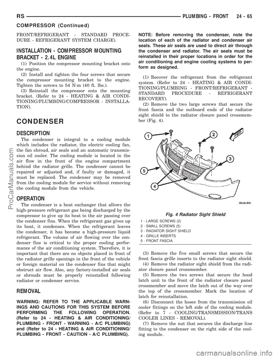
(2) Remove the two large screws that secure the
front fascia and the outboard ends of the radiator
sight shield to the radiator closure panel crossmem-
ber (Fig. 4).
(3) Remove the five small screws that secure the
front fascia grille inserts to the radiator sight shield.
(4) Remove the radiator sight shield from the radi-
ator closure panel crossmember.
(5) Remove the two screws that secure the hood
latch unit to the front of the radiator closure panel
crossmember and move the latch out of the way over
the top of the crossmember. Mark the location of
latch for reinstallation.
(6) Disconnect the hoses from the transmission oil
cooler fittings on the left side of the cooling module.
(Refer to 7 - COOLING/TRANSMISSION/TRANS
COOLER LINES - REMOVAL).
(7) Remove the nut that secures the discharge line
fitting to the condenser on the right side of the cool-
ing module.
Fig. 4 Radiator Sight Shield
1 - LARGE SCREWS (2)
2 - SMALL SCREWS (5)
3 - RADIATOR SIGHT SHIELD
4 - GRILLE INSERTS
5 - FRONT FASCIA
RSPLUMBING - FRONT24-65
COMPRESSOR (Continued)
ProCarManuals.com
Page 2309 of 2399
(8) Disconnect the discharge line fitting from the
condenser inlet port.
(9) Remove the seal from the discharge line fitting
and discard.
(10) Install plugs in, or tape over the opened dis-
charge line fitting and the condenser inlet port.
(11) Remove the nut that secures the liquid line
fitting to the condenser on the right side of the cool-
ing module.
(12) Disconnect the liquid line fitting from the con-
denser outlet port.
(13) Remove the seal from the liquid line fitting
and discard.
(14) Install plugs in, or tape over the opened liquid
line fitting and the condenser outlet port.
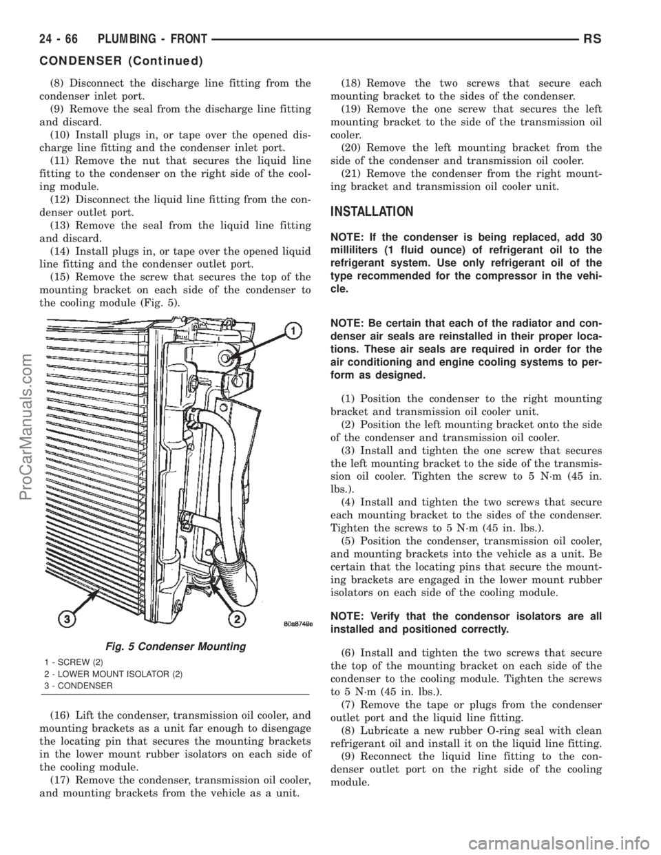
(15) Remove the screw that secures the top of the
mounting bracket on each side of the condenser to
the cooling module (Fig. 5).
(16) Lift the condenser, transmission oil cooler, and
mounting brackets as a unit far enough to disengage
the locating pin that secures the mounting brackets
in the lower mount rubber isolators on each side of
the cooling module.
(17) Remove the condenser, transmission oil cooler,
and mounting brackets from the vehicle as a unit.(18) Remove the two screws that secure each
mounting bracket to the sides of the condenser.
(19) Remove the one screw that secures the left
mounting bracket to the side of the transmission oil
cooler.
(20) Remove the left mounting bracket from the
side of the condenser and transmission oil cooler.
(21) Remove the condenser from the right mount-
ing bracket and transmission oil cooler unit.
INSTALLATION
NOTE: If the condenser is being replaced, add 30
milliliters (1 fluid ounce) of refrigerant oil to the
refrigerant system. Use only refrigerant oil of the
type recommended for the compressor in the vehi-
cle.
NOTE: Be certain that each of the radiator and con-
denser air seals are reinstalled in their proper loca-
tions. These air seals are required in order for the
air conditioning and engine cooling systems to per-
form as designed.
(1) Position the condenser to the right mounting
bracket and transmission oil cooler unit.
(2) Position the left mounting bracket onto the side
of the condenser and transmission oil cooler.
(3) Install and tighten the one screw that secures
the left mounting bracket to the side of the transmis-
sion oil cooler. Tighten the screw to 5 N´m (45 in.
lbs.).
(4) Install and tighten the two screws that secure
each mounting bracket to the sides of the condenser.
Tighten the screws to 5 N´m (45 in. lbs.).
(5) Position the condenser, transmission oil cooler,
and mounting brackets into the vehicle as a unit. Be
certain that the locating pins that secure the mount-
ing brackets are engaged in the lower mount rubber
isolators on each side of the cooling module.
NOTE: Verify that the condensor isolators are all
installed and positioned correctly.
(6) Install and tighten the two screws that secure
the top of the mounting bracket on each side of the
condenser to the cooling module. Tighten the screws
to 5 N´m (45 in. lbs.).
(7) Remove the tape or plugs from the condenser
outlet port and the liquid line fitting.
(8) Lubricate a new rubber O-ring seal with clean
refrigerant oil and install it on the liquid line fitting.
(9) Reconnect the liquid line fitting to the con-
denser outlet port on the right side of the cooling
module.
Fig. 5 Condenser Mounting
1 - SCREW (2)
2 - LOWER MOUNT ISOLATOR (2)
3 - CONDENSER
24 - 66 PLUMBING - FRONTRS
CONDENSER (Continued)
ProCarManuals.com