2002 CHRYSLER CARAVAN radiator
[x] Cancel search: radiatorPage 1448 of 2399
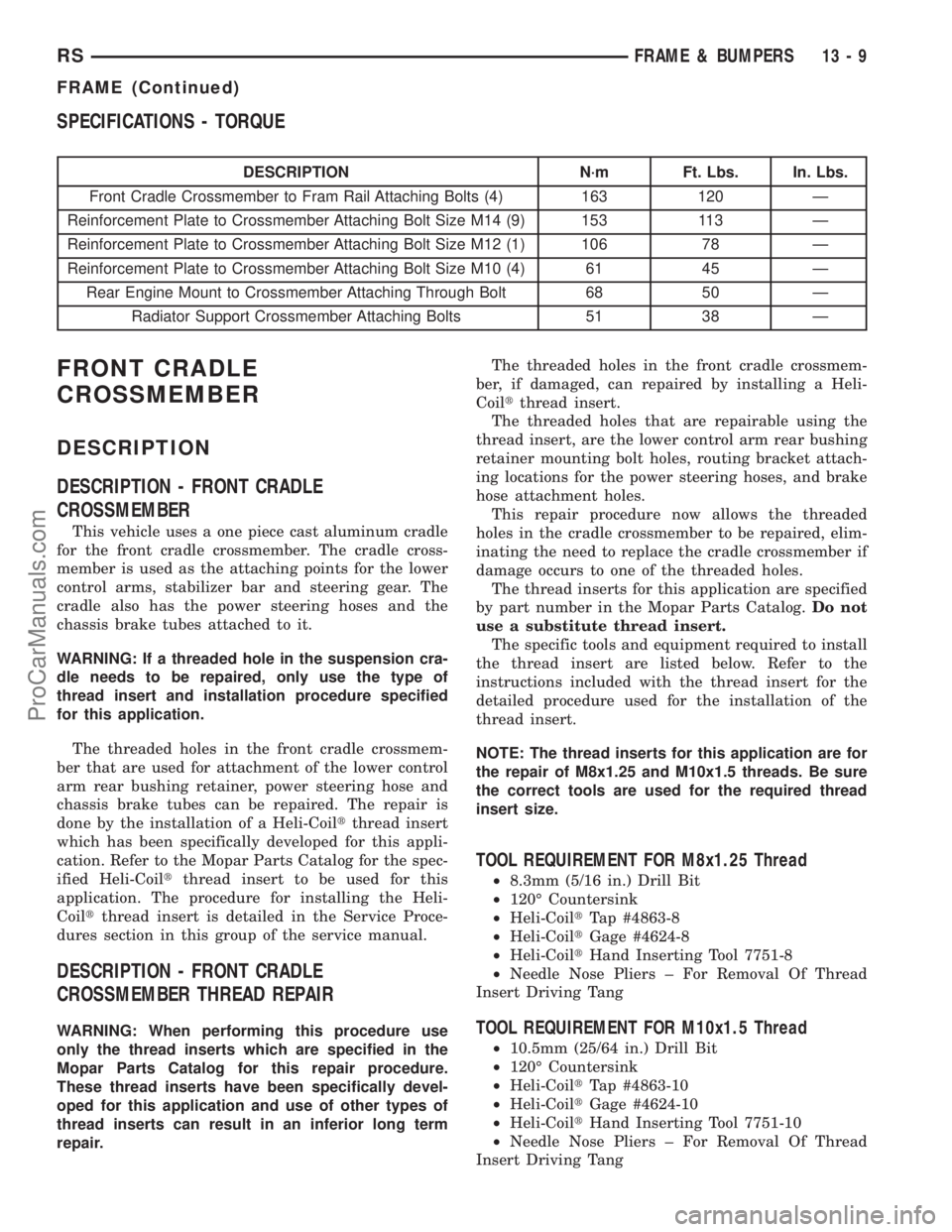
SPECIFICATIONS - TORQUE
DESCRIPTION N´m Ft. Lbs. In. Lbs.
Front Cradle Crossmember to Fram Rail Attaching Bolts (4) 163 120 Ð
Reinforcement Plate to Crossmember Attaching Bolt Size M14 (9) 153 113 Ð
Reinforcement Plate to Crossmember Attaching Bolt Size M12 (1) 106 78 Ð
Reinforcement Plate to Crossmember Attaching Bolt Size M10 (4) 61 45 Ð
Rear Engine Mount to Crossmember Attaching Through Bolt 68 50 Ð
Radiator Support Crossmember Attaching Bolts 51 38 Ð
FRONT CRADLE
CROSSMEMBER
DESCRIPTION
DESCRIPTION - FRONT CRADLE
CROSSMEMBER
This vehicle uses a one piece cast aluminum cradle
for the front cradle crossmember. The cradle cross-
member is used as the attaching points for the lower
control arms, stabilizer bar and steering gear. The
cradle also has the power steering hoses and the
chassis brake tubes attached to it.
WARNING: If a threaded hole in the suspension cra-
dle needs to be repaired, only use the type of
thread insert and installation procedure specified
for this application.
The threaded holes in the front cradle crossmem-
ber that are used for attachment of the lower control
arm rear bushing retainer, power steering hose and
chassis brake tubes can be repaired. The repair is
done by the installation of a Heli-Coiltthread insert
which has been specifically developed for this appli-
cation. Refer to the Mopar Parts Catalog for the spec-
ified Heli-Coiltthread insert to be used for this
application. The procedure for installing the Heli-
Coiltthread insert is detailed in the Service Proce-
dures section in this group of the service manual.
DESCRIPTION - FRONT CRADLE
CROSSMEMBER THREAD REPAIR
WARNING: When performing this procedure use
only the thread inserts which are specified in the
Mopar Parts Catalog for this repair procedure.
These thread inserts have been specifically devel-
oped for this application and use of other types of
thread inserts can result in an inferior long term
repair.The threaded holes in the front cradle crossmem-
ber, if damaged, can repaired by installing a Heli-
Coiltthread insert.
The threaded holes that are repairable using the
thread insert, are the lower control arm rear bushing
retainer mounting bolt holes, routing bracket attach-
ing locations for the power steering hoses, and brake
hose attachment holes.
This repair procedure now allows the threaded
holes in the cradle crossmember to be repaired, elim-
inating the need to replace the cradle crossmember if
damage occurs to one of the threaded holes.
The thread inserts for this application are specified
by part number in the Mopar Parts Catalog.Do not
use a substitute thread insert.
The specific tools and equipment required to install
the thread insert are listed below. Refer to the
instructions included with the thread insert for the
detailed procedure used for the installation of the
thread insert.
NOTE: The thread inserts for this application are for
the repair of M8x1.25 and M10x1.5 threads. Be sure
the correct tools are used for the required thread
insert size.
TOOL REQUIREMENT FOR M8x1.25 Thread
²8.3mm (5/16 in.) Drill Bit
²120É Countersink
²Heli-CoiltTap #4863-8
²Heli-CoiltGage #4624-8
²Heli-CoiltHand Inserting Tool 7751-8
²Needle Nose Pliers ± For Removal Of Thread
Insert Driving Tang
TOOL REQUIREMENT FOR M10x1.5 Thread
²10.5mm (25/64 in.) Drill Bit
²120É Countersink
²Heli-CoiltTap #4863-10
²Heli-CoiltGage #4624-10
²Heli-CoiltHand Inserting Tool 7751-10
²Needle Nose Pliers ± For Removal Of Thread
Insert Driving Tang
RSFRAME & BUMPERS13-9
FRAME (Continued)
ProCarManuals.com
Page 1579 of 2399
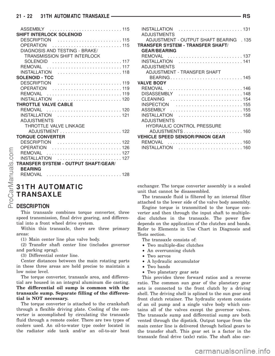
ASSEMBLY...........................115
SHIFT INTERLOCK SOLENOID
DESCRIPTION........................115
OPERATION..........................115
DIAGNOSIS AND TESTING - BRAKE/
TRANSMISSION SHIFT INTERLOCK
SOLENOID..........................117
REMOVAL............................117
INSTALLATION........................118
SOLENOID - TCC
DESCRIPTION........................119
OPERATION..........................119
REMOVAL............................119
INSTALLATION........................120
THROTTLE VALVE CABLE
REMOVAL............................120
INSTALLATION........................121
ADJUSTMENTS
THROTTLE VALVE LINKAGE
ADJUSTMENT.......................122
TORQUE CONVERTER
DESCRIPTION........................122
OPERATION..........................126
REMOVAL............................127
INSTALLATION........................127
TRANSFER SYSTEM - OUTPUT SHAFT/GEAR/
BEARING
REMOVAL............................128INSTALLATION........................131
ADJUSTMENTS
ADJUSTMENT - OUTPUT SHAFT BEARING . 135
TRANSFER SYSTEM - TRANSFER SHAFT/
GEAR/BEARING
REMOVAL............................137
INSTALLATION........................141
ADJUSTMENTS
ADJUSTMENT - TRANSFER SHAFT
BEARING...........................145
VALVE BODY
REMOVAL............................146
DISASSEMBLY........................148
CLEANING...........................154
INSPECTION.........................155
ASSEMBLY...........................155
INSTALLATION........................158
ADJUSTMENTS
HYDRAULIC CONTROL PRESSURE
ADJUSTMENTS......................160
VEHICLE SPEED SENSOR/PINION GEAR
REMOVAL............................160
INSTALLATION........................160
31TH AUTOMATIC
TRANSAXLE
DESCRIPTION
This transaxle combines torque converter, three
speed transmission, final drive gearing, and differen-
tial into a front wheel drive system.
Within this transaxle, there are three primary
areas:
(1) Main center line plus valve body.
(2) Transfer shaft center line (includes governor
and parking sprag).
(3) Differential center line.
Center distances between the main rotating parts
in these three areas are held precise to maintain a
low noise level.
The torque converter, transaxle area, and differen-
tial are housed in an integral aluminum die casting.
The differential oil sump is common with the
transaxle sump. Separate filling of the differen-
tial is NOT necessary.
The torque converter is attached to the crankshaft
through a flexible driving plate. Cooling of the con-
verter is accomplished by circulating the transaxle
fluid through a remote cooler. There are two types of
coolers used. An oil-to-water type cooler located in
the radiator side tank and/or an oil-to-air heatexchanger. The torque converter assembly is a sealed
unit that cannot be disassembled.
The transaxle fluid is filtered by an internal filter
attached to the lower side of the valve body assembly.
Engine torque is transmitted to the torque con-
verter and then through the input shaft to multiple-
disc clutches in the transaxle. The power flow
depends on the application of the clutches and bands.
Refer to Elements in Use Chart in Diagnosis and
Tests section.
The transaxle consists of:
²Two multiple-disc clutches
²An overrunning clutch
²Two servos
²A hydraulic accumulator
²Two bands
²Two planetary gear sets
This provides three forward ratios and a reverse
ratio. The common sun gear of the planetary gear
sets is connected to the front clutch by a driving
shell. The driving shell is splined to the sun gear and
front clutch retainer. The hydraulic system consists
of an oil pump and a single valve body which con-
tains all of the valves except the governor valves.
The transaxle sump and differential sump are both
vented through the dipstick. Output torque from the
main center line is delivered through helical gears to
the transfer shaft. This gear set is a factor in the
transaxle final drive (axle) ratio. The shaft also car-
21 - 22 31TH AUTOMATIC TRANSAXLERS
ProCarManuals.com
Page 1994 of 2399
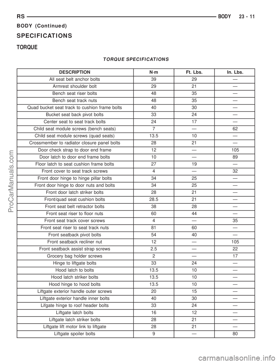
SPECIFICATIONS
TORQUE
TORQUE SPECIFICATIONS
DESCRIPTION N´m Ft. Lbs. In. Lbs.
All seat belt anchor bolts 39 29 Ð
Armrest shoulder bolt 29 21 Ð
Bench seat riser bolts 48 35 Ð
Bench seat track nuts 48 35 Ð
Quad bucket seat track to cushion frame bolts 40 30 Ð
Bucket seat back pivot bolts 33 24 Ð
Center seat to seat track bolts 24 17 Ð
Child seat module screws (bench seats) 7 Ð 62
Child seat module screws (quad seats) 13.5 10 Ð
Crossmember to radiator closure panel bolts 28 21 Ð
Door check strap to door end frame 12 Ð 105
Door latch to door end frame bolts 10 Ð 89
Floor latch to seat cushion frame bolts 27 19 Ð
Front cover to seat track screws 4 Ð 32
Front door hinge to hinge pillar bolts 34 25 Ð
Front door hinge to door nuts and bolts 34 25 Ð
Front door latch striker bolts 28 21 Ð
Front/quad seat cushion bolts 28.5 21 Ð
Front seat belt retractor bolts 38 28 Ð
Front seat riser to floor nuts 60 44 Ð
Front seat track cover screws 4 Ð 35
Front seat riser to seat track nuts 81 60 Ð
Front seatback pivot bolts 54 40 Ð
Front seatback recliner nut 12 Ð 105
Front seatback assist strap screws 2.5 Ð 22
Grocery bag holder screws 2 Ð 17
Hinge to liftgate bolts 33 24 Ð
Hood latch to bolts 13.5 10 Ð
Hood latch striker bolts 13.5 10 Ð
Hood hinge to hood bolts 13.5 10 Ð
Liftgate exterior handle outer screws 20 15 Ð
Liftgate exterior handle inner bolts 40 30 Ð
Lifgate hinge to roof header bolts 33 24 Ð
Liftgate latch bolts 16 12 Ð
Liftgate latch striker bolts 28 21 Ð
Liftgate lift motor link to liftgate 28 21 Ð
Liftgate spoiler bolts 9 Ð 80
RSBODY23-11
BODY (Continued)
ProCarManuals.com
Page 2037 of 2399

INSTALLATION
(1) Insert link into clip on fuel fill door.
(2) Engage clip to hold link to fuel fill door.
(3) Insert lockout link through grommet in panel
between inner and outer quarter panel.
(4) Close fuel fill door.
(5) Install fuel filler housing to outer quarter
panel.
(6) Verify that all clips on fuel filler housing are
fully engaged to outer quarter panel.
(7) Engage fuel filler lockout link into clip on fuel
fill blocker latch arm.
(8) Install water shield patch covering access hole
in C-pillar.
(9) Install left quarter trim panel.
GRILLE OPENING
REINFORCEMENT
REMOVAL
(1) Release hood latch and open hood.
(2) Remove bolts attaching hood latch to cross-
member and position latch out of the way.
(3) Remove radiator sight shield.
(4) Remove engine air inlet resonator.
(5) Remove hood cable.
(6) Remove hood prop rod.
(7) Remove screw attaching coolant recovery bottle
to crossmember.
(8) Remove bolts attaching radiator isolators to
crossmember.
(9) Remove bolts attaching ends of crossmember to
radiator closure panel (Fig. 14).
(10) Lift crossmember upward and away from
radiator closure panel.
(11) Remove crossmember from vehicle.
INSTALLATION
(1) Place radiator closure panel crossmember in
position on vehicle.
(2) Insert ends of crossmember between layered
metal sections of radiator closure panel at each side
of radiator.(3) Align with paint breaks around bolt heads.
(4) Install bolts attaching ends of crossmember to
radiator closure panel (Fig. 14) . Tighten bolts to 19
N´m (14 ft. lbs.) torque.
(5) Install bolts attaching radiator isolators to
crossmember.
(6) Install screw attaching coolant recovery bottle
to crossmember.
(7) Install bolt attaching air cleaner housing to
crossmember.
(8) Install engine air inlet resonator.
(9) Install radiator sight shield.
(10) Install hood prop rod.
(11) Align hood latch by placing latch over net
pierce tabs. If alignment is required, flatten tabs.
(12) Install bolts attaching hood latch to cross-
member. Tighten bolts to 13.5 N´m (10 ft. lbs.)
torque.
(13) Verify hood latch operation and hood align-
ment.
Fig. 14 RADIATOR CLOSURE PANEL
CROSSMEMBER
1 - RADIATOR CLOSURE PANEL CROSSMEMBER
2 - FRONT FASCIA
23 - 54 EXTERIORRS
FUEL FILL DOOR BLOCKER LOCKOUT LINK (Continued)
ProCarManuals.com
Page 2044 of 2399
INSTALLATION
(1) Place hood in position on vehicle. With assis-
tance from a helper at the opposite side of the vehicle
to support the hood, install bottom bolts attaching
hood to hinge finger tight.
(2) Install top bolts attaching hood to hinge finger
tight.
(3) Position bolts at marks and tighten. Tighten
bolts to 13.5 N´m (120 in. lbs.) torque. The hood
should be aligned to 4 mm (0.160 in.) gap to the front
fenders and flush across the top surfaces along fend-
ers.
(4) Verify hood operation and alignment.
LATCH
REMOVAL
(1) Release hood latch and open hood.
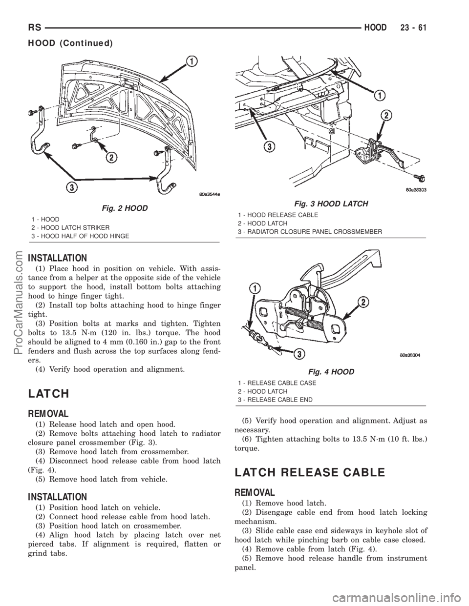
(2) Remove bolts attaching hood latch to radiator
closure panel crossmember (Fig. 3).
(3) Remove hood latch from crossmember.
(4) Disconnect hood release cable from hood latch
(Fig. 4).
(5) Remove hood latch from vehicle.
INSTALLATION
(1) Position hood latch on vehicle.
(2) Connect hood release cable from hood latch.
(3) Position hood latch on crossmember.
(4) Align hood latch by placing latch over net
pierced tabs. If alignment is required, flatten or
grind tabs.(5) Verify hood operation and alignment. Adjust as
necessary.
(6) Tighten attaching bolts to 13.5 N´m (10 ft. lbs.)
torque.
LATCH RELEASE CABLE
REMOVAL
(1) Remove hood latch.
(2) Disengage cable end from hood latch locking
mechanism.
(3) Slide cable case end sideways in keyhole slot of
hood latch while pinching barb on cable case closed.
(4) Remove cable from latch (Fig. 4).
(5) Remove hood release handle from instrument
panel.
Fig. 2 HOOD
1 - HOOD
2 - HOOD LATCH STRIKER
3 - HOOD HALF OF HOOD HINGE
Fig. 3 HOOD LATCH
1 - HOOD RELEASE CABLE
2 - HOOD LATCH
3 - RADIATOR CLOSURE PANEL CROSSMEMBER
Fig. 4 HOOD
1 - RELEASE CABLE CASE
2 - HOOD LATCH
3 - RELEASE CABLE END
RSHOOD23-61
HOOD (Continued)
ProCarManuals.com
Page 2045 of 2399
(6) Disengage rubber grommet cable insulator
from hole in dash panel.
(7) Attach a suitable length of mechanic's wire to
latch end of cable to assist cable installation.
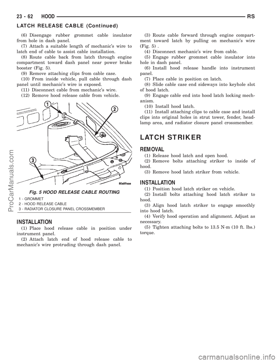
(8) Route cable back from latch through engine
compartment toward dash panel near power brake
booster (Fig. 5).
(9) Remove attaching clips from cable case.
(10) From inside vehicle, pull cable through dash
panel until mechanic's wire is exposed.
(11) Disconnect cable from mechanic's wire.
(12) Remove hood release cable from vehicle.
INSTALLATION
(1) Place hood release cable in position under
instrument panel.
(2) Attach latch end of hood release cable to
mechanic's wire protruding through dash panel.(3) Route cable forward through engine compart-
ment toward latch by pulling on mechanic's wire
(Fig. 5) .
(4) Disconnect mechanic's wire from cable.
(5) Engage rubber grommet cable insulator into
hole in dash panel.
(6) Install hood release handle into instrument
panel.
(7) Place cable in position on latch.
(8) Slide cable case end sideways into keyhole slot
of hood latch.
(9) Engage cable end into hood latch locking mech-
anism.
(10) Install hood latch.
(11) Install attaching clips to cable case and install
clips into original holes in strut tower, fender, head-
lamp area, and radiator closure panel crossmember.
LATCH STRIKER
REMOVAL
(1) Release hood latch and open hood.
(2) Remove bolts attaching striker to inside of
hood.
(3) Remove hood latch striker from vehicle.
INSTALLATION
(1) Position hood latch striker on vehicle.
(2) Install bolts attaching hood latch striker to
hood.
(3) Align hood latch striker to engage smoothly
into hood latch.
(4) Verify hood operation and alignment. Adjust as
necessary.
(5) Tighten attaching bolts to 13.5 N´m (10 ft. lbs.)
torque.Fig. 5 HOOD RELEASE CABLE ROUTING
1 - GROMMET
2 - HOOD RELEASE CABLE
3 - RADIATOR CLOSURE PANEL CROSSMEMBER
23 - 62 HOODRS
LATCH RELEASE CABLE (Continued)
ProCarManuals.com
Page 2139 of 2399
WELD LOCATIONS
SPECIFICATIONS
WELD LOCATIONS
INDEX
DESCRIPTION FIGURE
FRONT FENDER SHIELD - RIGHT 62
FRONT FENDER SHIELD - LEFT 63
STRUT TOWER AND REINFORCEMENTS - RIGHT 64
SUSPENSION RETAINERS AND REINFORCEMENTS - RIGHT 65
STRUT TOWER AND REINFORCEMENTS - LEFT 66
SUSPENSION RETAINERS AND REINFORCEMENTS - LEFT 67
FLOOR PAN REINFORCEMENTS - SIDE RAILS 68
REAR SUSPENSION BRACKETS 69
FLOOR PAN CROSS MEMBERS 70
SEAT REINFORCEMENTS - LONG WHEEL BASE ONLY 71
STRIKER REINFORCEMENTS - LONG WHEEL BASE ONLY 72
FUEL TANK MOUNTING/REAR SEAT AND SUSPENSION 73
REAR SUSPENSION HANGER BRACKETS - LONG WHEEL BASE 74
FRONT SEAT CROSS MEMBER 75
FLOOR PAN SIDE RAIL REINFORCEMENT 76
SILL BULKHEAD REINFORCEMENTS 77
FLOOR PAN CROSS MEMBER REINFORCEMENTS 78
FRONT SEAT CROSS MEMBER 79
SEAT REINFORCEMENT CROSS MEMBERS - SHORT WHEEL BASE 80
CENTER CONSOLE REINFORCEMENT - SHORT WHEEL BASE 81
REAR SUSPENSION HANGER BRACKETS - SHORT WHEEL BASE 82
LOWER LIFTGATE PANEL LATCH REINFORCEMENT 83
ENGINE MOUNTING PLATE AND TOW BRACKET 84
HEADLAMP MOUNTING PLATE 85
LOWER RADIATOR CROSS MEMBER BRACKETS 86
CROSS MEMBER EXTENSIONS 87
JACK MOUNTING BRACKET - LONG WHEEL BASE SHOWN, SHORT SIMILAR 88
FRONT SEAT CROSS MEMBER - LONG WHEELBASE ONLY 89
FRONT SEAT CROSS MEMBER - ALL WHEEL DRIVE ONLY 90
FUEL TANK SUPPORT CROSS MEMBERS - LONG WHEEL BASE ONLY 91
REAR SUPPORT AND TIRE STOWAGE CROSS MEMBERS - LONG WHEEL BASE
ONLY92
INNER SIDE SILLS - LONG WHEEL BASE ONLY 93
WHEELHOUSES, SIDE SILLS, SUSPENSION BRACKETS - LONG WHEEL BASE ONLY 94
REAR SEAT REINFORCEMENTS - SHORT WHEEL BASE ONLY 95
23 - 156 BODY STRUCTURERS
ProCarManuals.com
Page 2165 of 2399
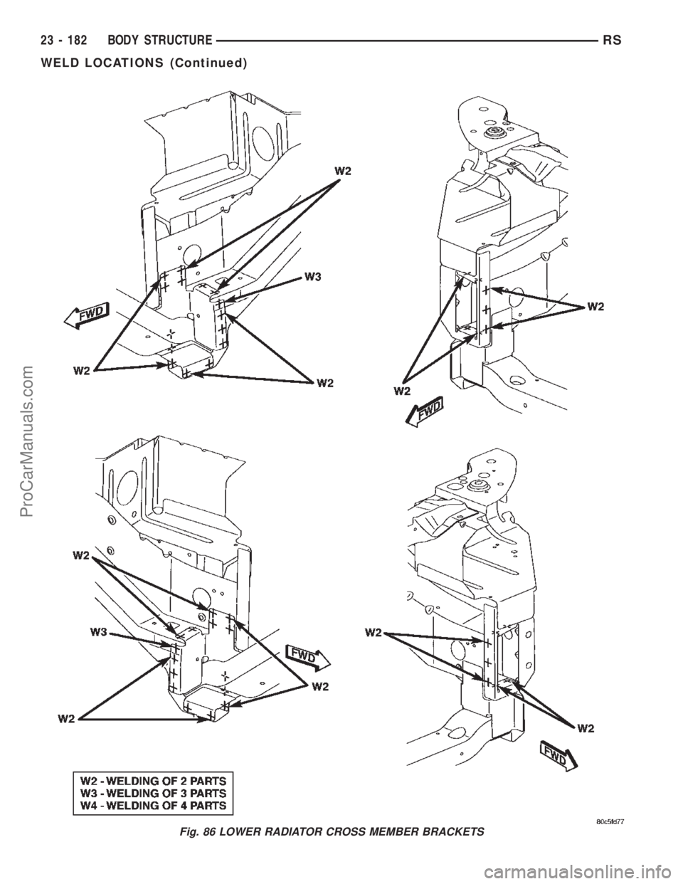
Fig. 86 LOWER RADIATOR CROSS MEMBER BRACKETS
23 - 182 BODY STRUCTURERS
WELD LOCATIONS (Continued)
ProCarManuals.com