Page 1907 of 2399
DISASSEMBLY
(1) Remove differential side bearings:
(a) Install button 8491-1 to differential case (Fig.
97).
(b) Set up Tool 5048 (5048-1, -4, -6) as shown in
(Fig. 98).
(c) Remove differential side bearing (Fig. 99).
Same procedure/tools work for both sides.
(2) Remove ring gear-to-case bolts (Fig. 100) and
remove ring gear.
Fig. 97 Tool 8491
1 - TOOL 8491
Fig. 98 Puller 5048
1 - 5048-1 FORCING SCREW
2 - 5048-4 COLLETS
3 - 5048-6 SLEEVE
Fig. 99 Differential Side Bearing Removal
1 - TOOL 5048
Fig. 100 Ring Gear-to-Differential Case Bolts
1 - BOLT (12)
2 - DIFFERENTIAL SUPPORT
3 - RING GEAR
21 - 350 T850 MANUAL TRANSAXLERS
DIFFERENTIAL (Continued)
ProCarManuals.com
Page 1908 of 2399
(3) Using three ring gear bolts as forcing screws
(Fig. 101), separate differential support from case
(Fig. 102).(4) Remove side gear thrust washer (Fig. 103).
(5) Remove side gear (Fig. 104).
Fig. 101 Separate Differential Case Halves
1 - BOLT (3)
2 - DIFFERENTIAL CASE
3 - DIFFERENTIAL SUPPORT
Fig. 102 Differential Support Plate
1 - DIFFERENTIAL SUPPORT PLATE
2 - DIFFERENTIAL CASE
Fig. 103 Side Gear Thrust Washer
1 - SIDE GEAR THRUST WASHER
2 - DIFFERENTIAL SIDE GEAR
Fig. 104 Differential Side Gear
1 - DIFFERENTIAL SIDE GEAR
RST850 MANUAL TRANSAXLE21 - 351
DIFFERENTIAL (Continued)
ProCarManuals.com
Page 1909 of 2399
(6) Remove long pinion shaft (Fig. 105).
(7) Remove both short pinion shafts (Fig. 106).(8) Remove pinion shaft retainer (Fig. 107).
(9) Remove four pinion gears and thrust washers
(Fig. 108).
Fig. 105 Long Pinion Shaft
1 - PINION SHAFT (LONG)
Fig. 106 Short Pinion Shaft (2)
1 - PINION SHAFT (SHORT (2))
Fig. 107 Pinion Shaft Retaining Ring
1 - RETAINING RING
Fig. 108 Pinion Gear and Thrust Washer
1 - THRUST WASHER (4)
2 - PINION GEAR (4)
21 - 352 T850 MANUAL TRANSAXLERS
DIFFERENTIAL (Continued)
ProCarManuals.com
Page 1910 of 2399
(10) Remove side gear (Fig. 109).
(11) Remove side gear thrust washer (Fig. 110).ASSEMBLY
(1) Install side gear thrust washer (Fig. 111).
(2) Install differential side gear (Fig. 112).
Fig. 109 Differential Side Gear
1 - DIFFERENTIAL SIDE GEAR
Fig. 110 Side Gear Thrust Washer
1 - SIDE GEAR THRUST WASHER
Fig. 111 Side Gear Thrust Washer
1 - SIDE GEAR THRUST WASHER
Fig. 112 Differential Side Gear
1 - DIFFERENTIAL SIDE GEAR
RST850 MANUAL TRANSAXLE21 - 353
DIFFERENTIAL (Continued)
ProCarManuals.com
Page 1911 of 2399
(3) Install four (4) pinion gears and thrust washers
(Fig. 113).
(4) Install pinion shaft retaining ring (Fig. 114).(5) Install two (2) short pinion shafts (Fig. 115).
(6) Install one (1) long pinion shaft (Fig. 116).
(7) Install differential side gear.
Fig. 113 Pinion Gear and Thrust Washer
1 - THRUST WASHER (4)
2 - PINION GEAR (4)
Fig. 114 Pinion Shaft Retaining Ring
1 - RETAINING RING
Fig. 115 Short Pinion Shaft (2)
1 - PINION SHAFT (SHORT (2))
Fig. 116 Long Pinion Shaft
1 - PINION SHAFT (LONG)
21 - 354 T850 MANUAL TRANSAXLERS
DIFFERENTIAL (Continued)
ProCarManuals.com
Page 1912 of 2399

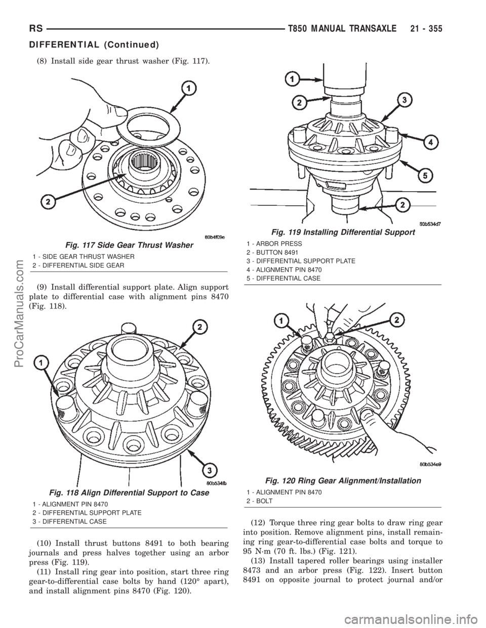
(8) Install side gear thrust washer (Fig. 117).
(9) Install differential support plate. Align support
plate to differential case with alignment pins 8470
(Fig. 118).
(10) Install thrust buttons 8491 to both bearing
journals and press halves together using an arbor
press (Fig. 119).
(11) Install ring gear into position, start three ring
gear-to-differential case bolts by hand (120É apart),
and install alignment pins 8470 (Fig. 120).(12) Torque three ring gear bolts to draw ring gear
into position. Remove alignment pins, install remain-
ing ring gear-to-differential case bolts and torque to
95 N´m (70 ft. lbs.) (Fig. 121).
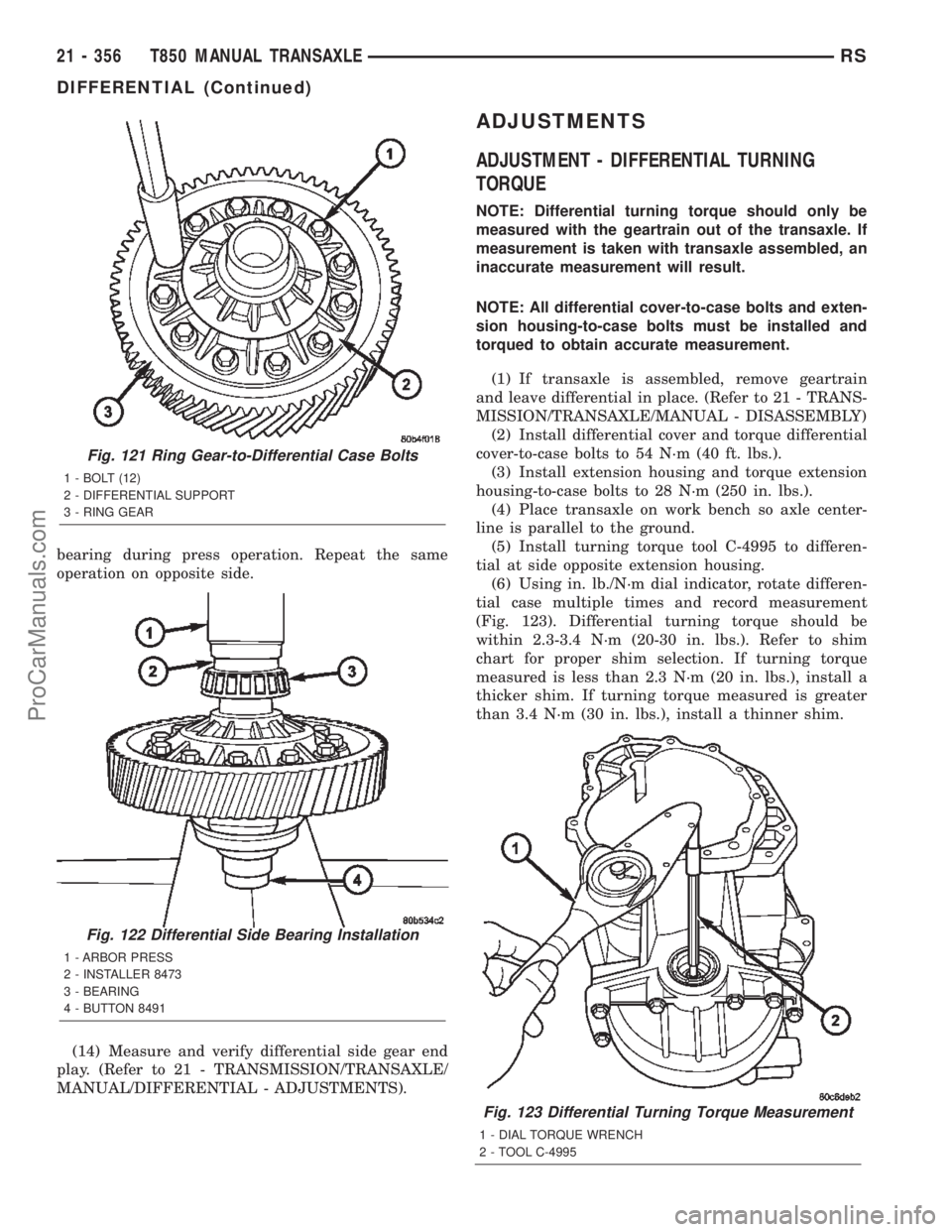
(13) Install tapered roller bearings using installer
8473 and an arbor press (Fig. 122). Insert button
8491 on opposite journal to protect journal and/or
Fig. 117 Side Gear Thrust Washer
1 - SIDE GEAR THRUST WASHER
2 - DIFFERENTIAL SIDE GEAR
Fig. 118 Align Differential Support to Case
1 - ALIGNMENT PIN 8470
2 - DIFFERENTIAL SUPPORT PLATE
3 - DIFFERENTIAL CASE
Fig. 119 Installing Differential Support
1 - ARBOR PRESS
2 - BUTTON 8491
3 - DIFFERENTIAL SUPPORT PLATE
4 - ALIGNMENT PIN 8470
5 - DIFFERENTIAL CASE
Fig. 120 Ring Gear Alignment/Installation
1 - ALIGNMENT PIN 8470
2 - BOLT
RST850 MANUAL TRANSAXLE21 - 355
DIFFERENTIAL (Continued)
ProCarManuals.com
Page 1913 of 2399

bearing during press operation. Repeat the same
operation on opposite side.
(14) Measure and verify differential side gear end
play. (Refer to 21 - TRANSMISSION/TRANSAXLE/
MANUAL/DIFFERENTIAL - ADJUSTMENTS).
ADJUSTMENTS
ADJUSTMENT - DIFFERENTIAL TURNING
TORQUE
NOTE: Differential turning torque should only be
measured with the geartrain out of the transaxle. If
measurement is taken with transaxle assembled, an
inaccurate measurement will result.
NOTE: All differential cover-to-case bolts and exten-
sion housing-to-case bolts must be installed and
torqued to obtain accurate measurement.
(1) If transaxle is assembled, remove geartrain
and leave differential in place. (Refer to 21 - TRANS-
MISSION/TRANSAXLE/MANUAL - DISASSEMBLY)
(2) Install differential cover and torque differential
cover-to-case bolts to 54 N´m (40 ft. lbs.).
(3) Install extension housing and torque extension
housing-to-case bolts to 28 N´m (250 in. lbs.).
(4) Place transaxle on work bench so axle center-
line is parallel to the ground.
(5) Install turning torque tool C-4995 to differen-
tial at side opposite extension housing.
(6) Using in. lb./N´m dial indicator, rotate differen-
tial case multiple times and record measurement
(Fig. 123). Differential turning torque should be
within 2.3-3.4 N´m (20-30 in. lbs.). Refer to shim
chart for proper shim selection. If turning torque
measured is less than 2.3 N´m (20 in. lbs.), install a
thicker shim. If turning torque measured is greater
than 3.4 N´m (30 in. lbs.), install a thinner shim.
Fig. 123 Differential Turning Torque Measurement
1 - DIAL TORQUE WRENCH
2 - TOOL C-4995
Fig. 121 Ring Gear-to-Differential Case Bolts
1 - BOLT (12)
2 - DIFFERENTIAL SUPPORT
3 - RING GEAR
Fig. 122 Differential Side Bearing Installation
1 - ARBOR PRESS
2 - INSTALLER 8473
3 - BEARING
4 - BUTTON 8491
21 - 356 T850 MANUAL TRANSAXLERS
DIFFERENTIAL (Continued)
ProCarManuals.com
Page 1914 of 2399
DIFFERENTIAL BEARING SHIM CHART
PART NUMBERSHIM THICKNESS
METRIC (MM) STANDARD (STD)
4659242 0.50 0.0197
4659243 0.54 0.0213
4659247 0.58 0.0228
4659248 0.62 0.0244
4659249 0.66 0.0260
4659250 0.70 0.0276
4659251 0.74 0.0291
4659252 0.78 0.0307
4659253 0.82 0.0322
4659254 0.86 0.0339
4659255 0.90 0.0354
4659256 0.94 0.0370
4659257 0.98 0.0386
4659258 1.02 0.0402
4659259 1.06 0.0418
4659260 1.10 0.0434
4659261 1.14 0.0449
4659262 1.18 0.0465
4659263 1.22 0.0481
4659264 1.26 0.0497
4659265 1.30 0.0512
4659266 1.34 0.0528
4659267 1.38 0.0544
4659268 1.42 0.0560
4659269 1.46 0.0575
4659270 1.50 0.0591
4659271 1.54 0.0607
4659272 1.58 0.0623
4659273 1.62 0.0638
4659274 1.66 0.0654
4659275 1.70 0.0670
4659283 2.02 0.0796
4659284 2.06 0.0812
RST850 MANUAL TRANSAXLE21 - 357
DIFFERENTIAL (Continued)
ProCarManuals.com