2002 CHRYSLER CARAVAN fuel pressure
[x] Cancel search: fuel pressurePage 2367 of 2399
chemical reaction takes place. This means the con-
centration of oxygen will be the same downstream as
upstream. The output voltage of the downstream
O2S copies the voltage of the upstream sensor. The
only difference is a time lag (seen by the PCM)
between the switching of the O2S's.
To monitor the system, the number of lean-to-rich
switches of upstream and downstream O2S's is
counted. The ratio of downstream switches to
upstream switches is used to determine whether the
catalyst is operating properly. An effective catalyst
will have fewer downstream switches than it has
upstream switches i.e., a ratio closer to zero. For a
totally ineffective catalyst, this ratio will be one-to-
one, indicating that no oxidation occurs in the device.
The system must be monitored so that when cata-
lyst efficiency deteriorates and exhaust emissions
increase to over the legal limit, the MIL (Check
Engine lamp) will be illuminated.
LEAK DETECTION PUMP MONITOR (if equipped)
The leak detection assembly incorporates two pri-
mary functions: it must detect a leak in the evapora-
tive system and seal the evaporative system so the
leak detection test can be run.
The primary components within the assembly are:
A three port solenoid that activates both of the func-
tions listed above; a pump which contains a switch,
two check valves, a spring/diaphragm, and a canister
vent valve (CVV) seal which contains a spring loaded
vent seal valve.
Immediately after a cold start, between predeter-
mined temperature thresholds limits, the three port
solenoid is briefly energized. This initializes the
pump by drawing air into the pump cavity and also
closes the vent seal. During non test conditions the
vent seal is held open by the pump diaphragm
assembly which pushes it open at the full travel posi-
tion. The vent seal will remain closed while the
pump is cycling due to the reed switch triggering of
the three port solenoid that prevents the diaphragm
assembly from reaching full travel. After the brief
initialization period, the solenoid is de-energized
allowing atmospheric pressure to enter the pump
cavity, thus permitting the spring to drive the dia-
phragm which forces air out of the pump cavity and
into the vent system. When the solenoid is energized
and de energized, the cycle is repeated creating flow
in typical diaphragm pump fashion. The pump is con-
trolled in 2 modes:
Pump Mode:The pump is cycled at a fixed rate to
achieve a rapid pressure build in order to shorten the
overall test length.
Test Mode:The solenoid is energized with a fixed
duration pulse. Subsequent fixed pulses occur when
the diaphragm reaches the Switch closure point.The spring in the pump is set so that the system
will achieve an equalized pressure of about 7.5º
water. The cycle rate of pump strokes is quite rapid
as the system begins to pump up to this pressure. As
the pressure increases, the cycle rate starts to drop
off. If there is no leak in the system, the pump would
eventually stop pumping at the equalized pressure. If
there is a leak, it will continue to pump at a rate rep-
resentative of the flow characteristic of the size of the
leak. From this information we can determine if the
leak is larger than the required detection limit (cur-
rently set at .020º orifice by CARB). If a leak is
revealed during the leak test portion of the test, the
test is terminated at the end of the test mode and no
further system checks will be performed.
The canister vent valve will unseal the system
after completion of the test sequence as the pump
diaphragm assembly moves to the full travel position.
Evaporative system functionality will be verified by
using the stricter evap purge flow monitor. At an
appropriate warm idle the LDP will be energized to
seal the canister vent. The purge flow will be clocked
up from some small value in an attempt to see a
shift in the 02 control system. If fuel vapor, indicated
by a shift in the 02 control, is present the test is
passed. If not, it is assumed that the purge system is
not functioning in some respect. The LDP is again
turned off and the test is ended.
Natural Vacuum Leak Detection (NVLD) (if equipped)
The Natural Vacuum Leak Detection (NVLD) sys-
tem is the next generation evaporative leak detection
system that will first be used on vehicles equipped
with the Next Generation Controller (NGC) starting
in 2002 M.Y. This new system replaces the leak
detection pump as the method of evaporative system
leak detection. This is to detect a leak equivalent to a
0.0209(0.5 mm) hole. This system has the capability
to detect holes of this size very dependably.
The basic leak detection theory employed with
NVLD is the9Gas Law9. This is to say that the pres-
sure in a sealed vessel will change if the temperature
of the gas in the vessel changes. The vessel will only
see this effect if it is indeed sealed. Even small leaks
will allow the pressure in the vessel to come to equi-
librium with the ambient pressure. In addition to the
detection of very small leaks, this system has the
capability of detecting medium as well as large evap-
orative system leaks.
A vent valve seals the canister vent during engine
off conditions. If the vapor system has a leak of less
than the failure threshold, the evaporative system
will be pulled into a vacuum, either due to the cool
down from operating temperature or diurnal ambient
temperature cycling. The diurnal effect is considered
one of the primary contributors to the leak determi-
25 - 8 EMISSIONS CONTROLRS
EMISSIONS CONTROL (Continued)
ProCarManuals.com
Page 2368 of 2399
nation by this diagnostic. When the vacuum in the
system exceeds about 19H2O (0.25 KPA), a vacuum
switch closes. The switch closure sends a signal to
the NGC. The NGC, via appropriate logic strategies
(described below), utilizes the switch signal, or lack
thereof, to make a determination of whether a leak is
present.
The NVLD device is designed with a normally open
vacuum switch, a normally closed solenoid, and a
seal, which is actuated by both the solenoid and a
diaphragm. The NVLD is located on the atmospheric
vent side of the canister. The NVLD assembly may
be mounted on top of the canister outlet, or in-line
between the canister and atmospheric vent filter. The
normally open vacuum switch will close with about 19
H2O (0.25 KPA) vacuum in the evaporative system.
The diaphragm actuates the switch. This is above the
opening point of the fuel inlet check valve in the fill
tube so cap off leaks can be detected. Submerged fill
systems must have recirculation lines that do not
have the in-line normally closed check valve that pro-
tects the system from failed nozzle liquid ingestion,
in order to detect cap off conditions.
The normally closed valve in the NVLD is intended
to maintain the seal on the evaporative system dur-
ing the engine off condition. If vacuum in the evapo-
rative system exceeds 39to 69H2O (0.75 to 1.5 KPA),
the valve will be pulled off the seat, opening the seal.
This will protect the system from excessive vacuum
as well as allowing sufficient purge flow in the event
that the solenoid was to become inoperative.
The solenoid actuates the valve to unseal the can-
ister vent while the engine is running. It also will be
used to close the vent during the medium and large
leak tests and during the purge flow check. This sole-
noid requires initial 1.5 amps of current to pull the
valve open but after 100 ms. will be duty cycled down
to an average of about 150 mA for the remainder of
the drive cycle.
Another feature in the device is a diaphragm that
will open the seal in the NVLD with pressure in the
evaporative system. The device will9blow off9at
about 0.59H2O (0.12 KPA) pressure to permit the
venting of vapors during refueling. An added benefit
to this is that it will also allow the tank to9breathe9
during increasing temperatures, thus limiting the
pressure in the tank to this low level. This is benefi-
cial because the induced vacuum during a subse-
quent declining temperature will achieve the switch
closed (pass threshold) sooner than if the tank had to
decay from a built up pressure.
The device itself has 3 wires: Switch sense, sole-
noid driver and ground. It also includes a resistor to
protect the switch from a short to battery or a short
to ground. The NGC utilizes a high-side driver to
energize and duty-cycle the solenoid.DESCRIPTION - HIGH AND LOW LIMITS
The PCM compares input signal voltages from each
input device with established high and low limits for
the device. If the input voltage is not within limits
and other criteria are met, the PCM stores a diagnos-
tic trouble code in memory. Other diagnostic trouble
code criteria might include engine RPM limits or
input voltages from other sensors or switches that
must be present before verifying a diagnostic trouble
code condition.
OPERATION
OPERATION - SYSTEM
The Powertrain Control Module (PCM) monitors
many different circuits in the fuel injection, ignition,
emission and engine systems. If the PCM senses a
problem with a monitored circuit often enough to
indicate an actual problem, it stores a Diagnostic
Trouble Code (DTC) in the PCM's memory. If the
code applies to a non-emissions related component or
system, and the problem is repaired or ceases to
exist, the PCM cancels the code after 40 warmup
cycles. Diagnostic trouble codes that affect vehicle
emissions illuminate the Malfunction Indicator Lamp
(MIL). Refer to Malfunction Indicator Lamp in this
section.
Certain criteria must be met before the PCM
stores a DTC in memory. The criteria may be a spe-
cific range of engine RPM, engine temperature,
and/or input voltage to the PCM.
The PCM might not store a DTC for a monitored
circuit even though a malfunction has occurred. This
may happen because one of the DTC criteria for the
circuit has not been met.For example, assume the
diagnostic trouble code criteria requires the PCM to
monitor the circuit only when the engine operates
between 750 and 2000 RPM. Suppose the sensor's
output circuit shorts to ground when engine operates
above 2400 RPM (resulting in 0 volt input to the
PCM). Because the condition happens at an engine
speed above the maximum threshold (2000 rpm), the
PCM will not store a DTC.
There are several operating conditions for which
the PCM monitors and sets DTC's. Refer to Moni-
tored Systems, Components, and Non-Monitored Cir-
cuits in this section.
NOTE: Various diagnostic procedures may actually
cause a diagnostic monitor to set a DTC. For
instance, pulling a spark plug wire to perform a
spark test may set the misfire code. When a repair
is completed and verified, use the DRBIIITscan tool
to erase all DTC's and extinguish the MIL.
RSEMISSIONS CONTROL25-9
EMISSIONS CONTROL (Continued)
ProCarManuals.com
Page 2372 of 2399
EVAP/PURGE SOLENOID
DESCRIPTION
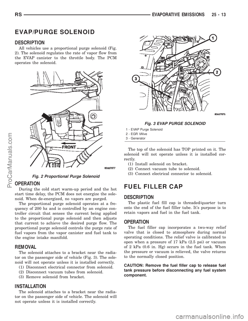
All vehicles use a proportional purge solenoid (Fig.
2). The solenoid regulates the rate of vapor flow from
the EVAP canister to the throttle body. The PCM
operates the solenoid.
OPERATION
During the cold start warm-up period and the hot
start time delay, the PCM does not energize the sole-
noid. When de-energized, no vapors are purged.
The proportional purge solenoid operates at a fre-
quency of 200 hz and is controlled by an engine con-
troller circuit that senses the current being applied
to the proportional purge solenoid and then adjusts
that current to achieve the desired purge flow. The
proportional purge solenoid controls the purge rate of
fuel vapors from the vapor canister and fuel tank to
the engine intake manifold.
REMOVAL
The solenoid attaches to a bracket near the radia-
tor on the passenger side of vehicle (Fig. 3). The sole-
noid will not operate unless it is installed correctly.
(1) Disconnect electrical connector from solenoid.
(2) Disconnect vacuum tubes from solenoid.
(3) Remove solenoid from bracket.
INSTALLATION
The solenoid attaches to a bracket near the radia-
tor on the passenger side of vehicle. The solenoid will
not operate unless it is installed correctly.The top of the solenoid has TOP printed on it. The
solenoid will not operate unless it is installed cor-
rectly.
(1) Install solenoid on bracket.
(2) Connect vacuum tube to solenoid.
(3) Connect electrical connector to solenoid.
FUEL FILLER CAP
DESCRIPTION
The plastic fuel fill cap is threaded/quarter turn
onto the end of the fuel filler tube. It's purpose is to
retain vapors and fuel in the fuel tank.
OPERATION
The fuel filler cap incorporates a two-way relief
valve that is closed to atmosphere during normal
operating conditions. The relief valve is calibrated to
open when a pressure of 17 kPa (2.5 psi) or vacuum
of 2 kPa (0.6 in. Hg) occurs in the fuel tank. When
the pressure or vacuum is relieved, the valve returns
to the normally closed position.
CAUTION: Remove the fuel filler cap to release fuel
tank pressure before disconnecting any fuel system
component.
Fig. 2 Proportional Purge Solenoid
Fig. 3 EVAP PURGE SOLENOID
1 - EVAP Purge Solenoid
2 - EGR VAlve
3 - Generator
RSEVAPORATIVE EMISSIONS25-13
ProCarManuals.com
Page 2373 of 2399
LEAK DETECTION PUMP
REMOVAL
(1) Disconnect the negative battery cable.
(2) Raise and support the vehicle.
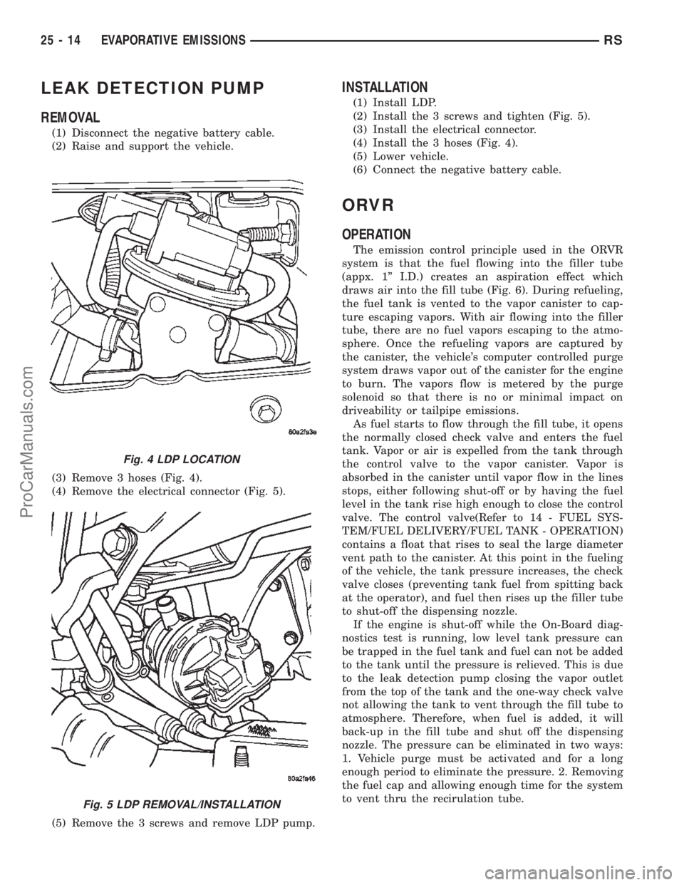
(3) Remove 3 hoses (Fig. 4).
(4) Remove the electrical connector (Fig. 5).
(5) Remove the 3 screws and remove LDP pump.
INSTALLATION
(1) Install LDP.
(2) Install the 3 screws and tighten (Fig. 5).
(3) Install the electrical connector.
(4) Install the 3 hoses (Fig. 4).
(5) Lower vehicle.
(6) Connect the negative battery cable.
ORVR
OPERATION
The emission control principle used in the ORVR
system is that the fuel flowing into the filler tube
(appx. 1º I.D.) creates an aspiration effect which
draws air into the fill tube (Fig. 6). During refueling,
the fuel tank is vented to the vapor canister to cap-
ture escaping vapors. With air flowing into the filler
tube, there are no fuel vapors escaping to the atmo-
sphere. Once the refueling vapors are captured by
the canister, the vehicle's computer controlled purge
system draws vapor out of the canister for the engine
to burn. The vapors flow is metered by the purge
solenoid so that there is no or minimal impact on
driveability or tailpipe emissions.
As fuel starts to flow through the fill tube, it opens
the normally closed check valve and enters the fuel
tank. Vapor or air is expelled from the tank through
the control valve to the vapor canister. Vapor is
absorbed in the canister until vapor flow in the lines
stops, either following shut-off or by having the fuel
level in the tank rise high enough to close the control
valve. The control valve(Refer to 14 - FUEL SYS-
TEM/FUEL DELIVERY/FUEL TANK - OPERATION)
contains a float that rises to seal the large diameter
vent path to the canister. At this point in the fueling
of the vehicle, the tank pressure increases, the check
valve closes (preventing tank fuel from spitting back
at the operator), and fuel then rises up the filler tube
to shut-off the dispensing nozzle.
If the engine is shut-off while the On-Board diag-
nostics test is running, low level tank pressure can
be trapped in the fuel tank and fuel can not be added
to the tank until the pressure is relieved. This is due
to the leak detection pump closing the vapor outlet
from the top of the tank and the one-way check valve
not allowing the tank to vent through the fill tube to
atmosphere. Therefore, when fuel is added, it will
back-up in the fill tube and shut off the dispensing
nozzle. The pressure can be eliminated in two ways:
1. Vehicle purge must be activated and for a long
enough period to eliminate the pressure. 2. Removing
the fuel cap and allowing enough time for the system
to vent thru the recirulation tube.
Fig. 4 LDP LOCATION
Fig. 5 LDP REMOVAL/INSTALLATION
25 - 14 EVAPORATIVE EMISSIONSRS
ProCarManuals.com
Page 2377 of 2399
noise will be heard as air passes through the valve. A
strong vacuum should also be felt when a finger is
placed over the valve inlet.
(2) Install hose on PCV valve. Remove the
make-up air hose from the air plenum at the rear of
the engine. Hold a piece of stiff paper (parts tag)
loosely over the end of the make-up air hose.
(3) After allowing approximately one minute for
crankcase pressure to reduce, the paper should draw
up against the hose with noticeable force. If the
engine does not draw the paper against the grommet
after installing a new valve, replace the PCV valve
hose.
(4) Turn the engine off. Remove the PCV valve
from intake manifold. The valve should rattle when
shaken.
(5) Replace the PCV valve and retest the system if
it does not operate as described in the preceding
tests.Do not attempt to clean the old PCV valve.
If the valve rattles, apply a light coating of Loctitet
Pipe Sealant With Teflon to the threads. Thread the
PCV valve into the manifold plenum and tighten to 7
N´m (60 in. lbs.) torque.
VAPOR CANISTER
DESCRIPTION
There are 2 EVAP canisters on the vehicle. The
vacuum and vapor tubes connect to the top of the
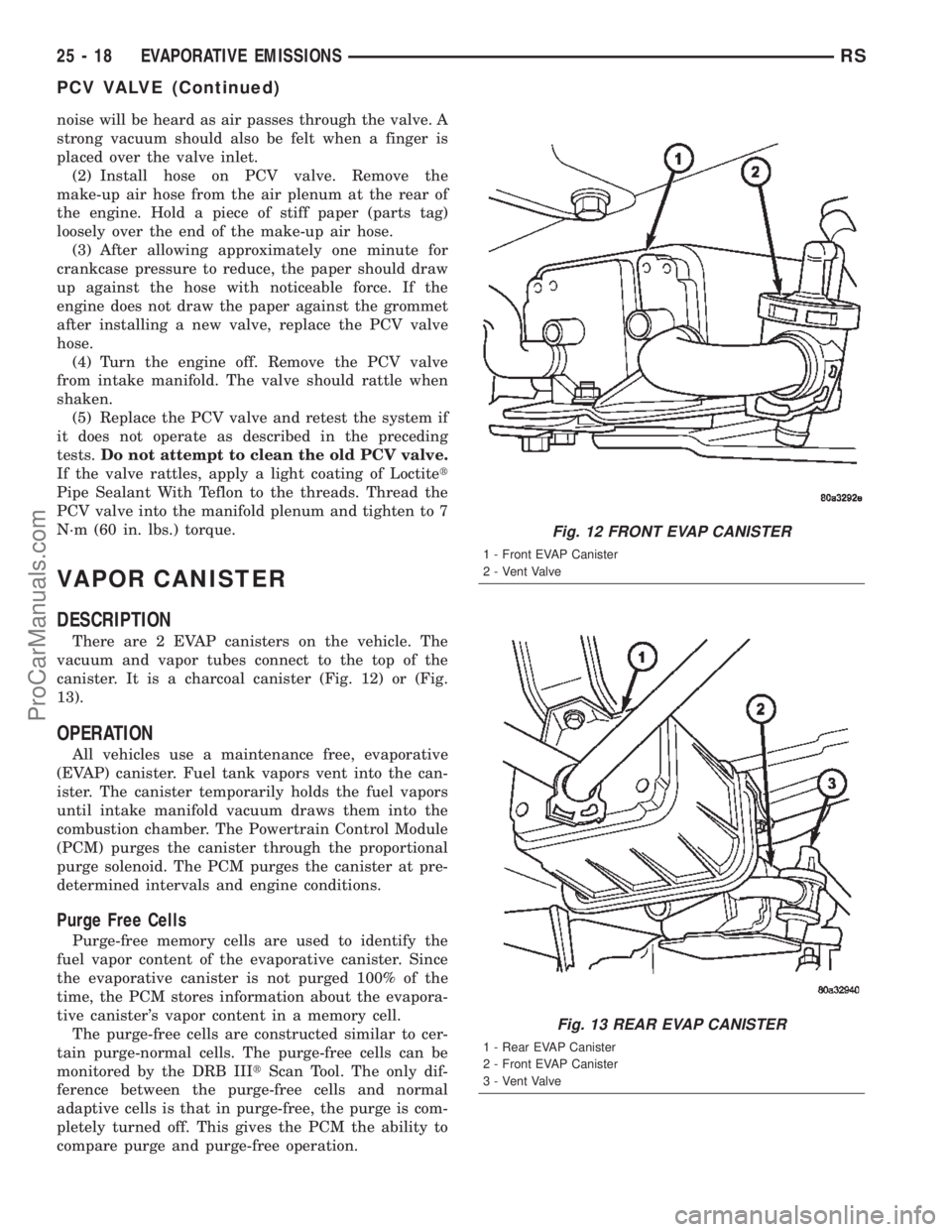
canister. It is a charcoal canister (Fig. 12) or (Fig.
13).
OPERATION
All vehicles use a maintenance free, evaporative
(EVAP) canister. Fuel tank vapors vent into the can-
ister. The canister temporarily holds the fuel vapors
until intake manifold vacuum draws them into the
combustion chamber. The Powertrain Control Module
(PCM) purges the canister through the proportional
purge solenoid. The PCM purges the canister at pre-
determined intervals and engine conditions.
Purge Free Cells
Purge-free memory cells are used to identify the
fuel vapor content of the evaporative canister. Since
the evaporative canister is not purged 100% of the
time, the PCM stores information about the evapora-
tive canister's vapor content in a memory cell.
The purge-free cells are constructed similar to cer-
tain purge-normal cells. The purge-free cells can be
monitored by the DRB IIItScan Tool. The only dif-
ference between the purge-free cells and normal
adaptive cells is that in purge-free, the purge is com-
pletely turned off. This gives the PCM the ability to
compare purge and purge-free operation.
Fig. 12 FRONT EVAP CANISTER
1 - Front EVAP Canister
2 - Vent Valve
Fig. 13 REAR EVAP CANISTER
1 - Rear EVAP Canister
2 - Front EVAP Canister
3 - Vent Valve
25 - 18 EVAPORATIVE EMISSIONSRS
PCV VALVE (Continued)
ProCarManuals.com
Page 2381 of 2399
the incoming air/fuel mixture. The diluted air/fuel
mixture reduces peak flame temperature during com-
bustion.
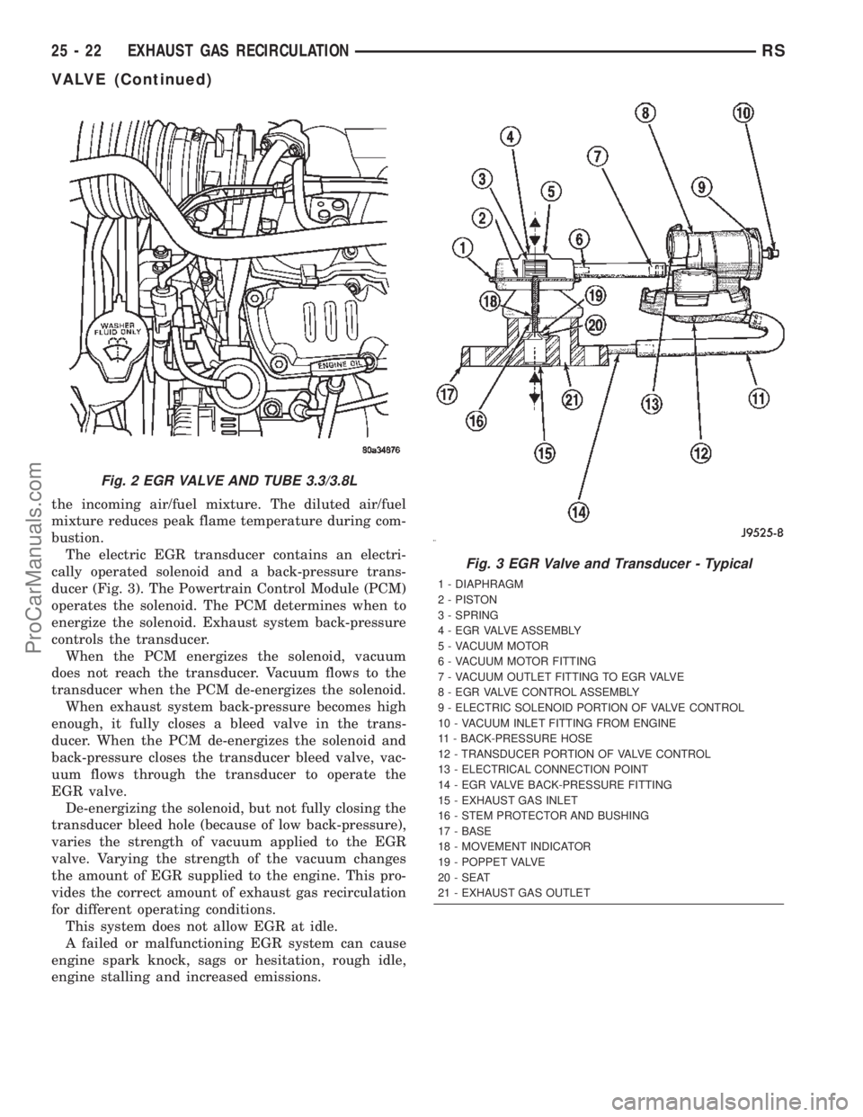
The electric EGR transducer contains an electri-
cally operated solenoid and a back-pressure trans-
ducer (Fig. 3). The Powertrain Control Module (PCM)
operates the solenoid. The PCM determines when to
energize the solenoid. Exhaust system back-pressure
controls the transducer.
When the PCM energizes the solenoid, vacuum
does not reach the transducer. Vacuum flows to the
transducer when the PCM de-energizes the solenoid.
When exhaust system back-pressure becomes high
enough, it fully closes a bleed valve in the trans-
ducer. When the PCM de-energizes the solenoid and
back-pressure closes the transducer bleed valve, vac-
uum flows through the transducer to operate the
EGR valve.
De-energizing the solenoid, but not fully closing the
transducer bleed hole (because of low back-pressure),
varies the strength of vacuum applied to the EGR
valve. Varying the strength of the vacuum changes
the amount of EGR supplied to the engine. This pro-
vides the correct amount of exhaust gas recirculation
for different operating conditions.
This system does not allow EGR at idle.
A failed or malfunctioning EGR system can cause
engine spark knock, sags or hesitation, rough idle,
engine stalling and increased emissions.
Fig. 2 EGR VALVE AND TUBE 3.3/3.8L
Fig. 3 EGR Valve and Transducer - Typical
1 - DIAPHRAGM
2 - PISTON
3 - SPRING
4 - EGR VALVE ASSEMBLY
5 - VACUUM MOTOR
6 - VACUUM MOTOR FITTING
7 - VACUUM OUTLET FITTING TO EGR VALVE
8 - EGR VALVE CONTROL ASSEMBLY
9 - ELECTRIC SOLENOID PORTION OF VALVE CONTROL
10 - VACUUM INLET FITTING FROM ENGINE
11 - BACK-PRESSURE HOSE
12 - TRANSDUCER PORTION OF VALVE CONTROL
13 - ELECTRICAL CONNECTION POINT
14 - EGR VALVE BACK-PRESSURE FITTING
15 - EXHAUST GAS INLET
16 - STEM PROTECTOR AND BUSHING
17 - BASE
18 - MOVEMENT INDICATOR
19 - POPPET VALVE
20 - SEAT
21 - EXHAUST GAS OUTLET
25 - 22 EXHAUST GAS RECIRCULATIONRS
VALVE (Continued)
ProCarManuals.com
Page 2388 of 2399
EMISSIONS CONTROL 2.5L TURBO DIESEL
TABLE OF CONTENTS
page page
EMISSIONS CONTROL 2.5L TURBO DIESEL
DESCRIPTION..........................1
SPECIFICATIONS - TORQUE...............2EXHAUST GAS RECIRCULATION............3
ON-BOARD DIAGNOSTICS.................6
EMISSIONS CONTROL 2.5L
TURBO DIESEL
DESCRIPTION
The 2.5L diesel Engine Control Module (ECM) con-
trols many different circuits in the fuel injection
pump and engine systems. If the ECM senses a prob-
lem with a monitored circuit that indicates an actual
problem, a Diagnostic Trouble Code (DTC) will be
stored in the ECM's memory, and eventually may
illuminate the MIL (Malfunction Indicator Lamp)
constantly while the key is on. If the problem is
repaired, or is intermittent, the ECM will erase the
DTC after 40 warm-up cycles without the the fault
detected. A warm-up cycle consists of starting the
vehicle when the engine is cold, then the engine is
warmed up to a certain temperature, and finally, the
engine temperature falls to a normal operating tem-
perature, then the key is turned off.
Certain criteria must be met for a DTC to be
entered into ECM memory. The criteria may be a
specific range of engine rpm, engine or fuel tempera-
ture and/or input voltage to the ECM. A DTC indi-
cates that the ECM has identified an abnormal
signal in a circuit or the system.
There are several operating conditions that the
ECM does not monitor and set a DTC for. Refer to
the following Monitored Circuits and Non±Monitored
Circuits in this section.
ECM MONITORED SYSTEMS
The ECM can detect certain problems in the elec-
trical system.
Open or Shorted Circuit± The ECM will not
distinguish between an open or a short to ground,
however the ECM can determine if there is excessive
current on a circuit, such as a short to voltage or a
decrease in component resistance.
Output Device Current Flow± The ECM senses
whether the output devices are electrically connected.
If there is a problem with the circuit, the ECM
senses whether the circuit is open, shorted to ground
(±), or shorted to (+) voltage.Fuel Pressure:Fuel pressure is controlled by the
fuel injection pump and fuel pressure solenoid. The
ECM uses a fuel pressure sensor to determine if a
fuel pressure problem exists.
Fuel Injector Malfunctions:The ECM can deter-
mine if a fuel injector has an electrical problem. The
fuel injectors on the diesel engine arecontrolledby
the ECM.
ECM NON±MONITORED SYSTEMS
The ECM does not monitor the following circuits,
systems or conditions that could have malfunctions
that result in driveability problems. A DTC will not
be displayed for these conditions.
Cylinder Compression:The ECM cannot detect
uneven, low, or high engine cylinder compression.
Exhaust System:The ECM cannot detect a
plugged, restricted or leaking exhaust system.
Vacuum Assist:Leaks or restrictions in the vac-
uum circuits of the Exhaust Gas Recirculation Sys-
tem (EGR) are not monitored by the ECM.
ECM System Ground:The ECM cannot deter-
mine a poor system ground. However, a DTC may be
generated as a result of this condition.
ECM/PCM Connector Engagement:The ECM
cannot determine spread or damaged connector pins.
However, a DTC may be generated as a result of this
condition.
HIGH AND LOW LIMITS
The ECM compares input signals from each input
device. It has high and low limits that are pro-
grammed into it for that device. If the inputs are not
within specifications and other DTC criteria are met,
a DTC will be stored in memory. Other DTC criteria
might include engine rpm limits or input voltages
from other sensors or switches. The other inputs
might have to be sensed by the ECM when it senses
a high or low input voltage from the control system
device in question.
RGEMISSIONS CONTROL 2.5L TURBO DIESEL25a-1
ProCarManuals.com
Page 2394 of 2399
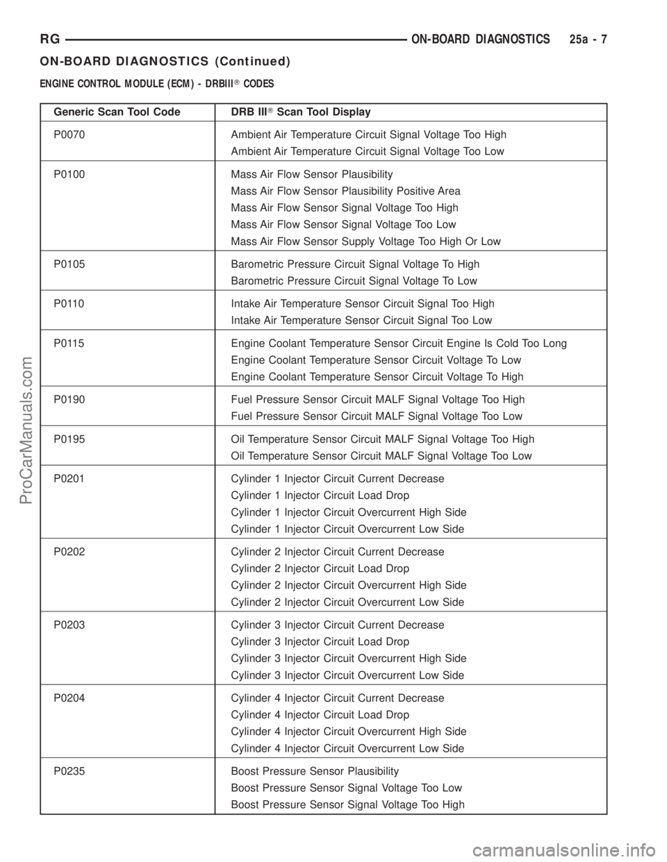
ENGINE CONTROL MODULE (ECM) - DRBIIITCODES
Generic Scan Tool Code DRB IIITScan Tool Display
P0070 Ambient Air Temperature Circuit Signal Voltage Too High
Ambient Air Temperature Circuit Signal Voltage Too Low
P0100 Mass Air Flow Sensor Plausibility
Mass Air Flow Sensor Plausibility Positive Area
Mass Air Flow Sensor Signal Voltage Too High
Mass Air Flow Sensor Signal Voltage Too Low
Mass Air Flow Sensor Supply Voltage Too High Or Low
P0105 Barometric Pressure Circuit Signal Voltage To High
Barometric Pressure Circuit Signal Voltage To Low
P0110 Intake Air Temperature Sensor Circuit Signal Too High
Intake Air Temperature Sensor Circuit Signal Too Low
P0115 Engine Coolant Temperature Sensor Circuit Engine Is Cold Too Long
Engine Coolant Temperature Sensor Circuit Voltage To Low
Engine Coolant Temperature Sensor Circuit Voltage To High
P0190 Fuel Pressure Sensor Circuit MALF Signal Voltage Too High
Fuel Pressure Sensor Circuit MALF Signal Voltage Too Low
P0195 Oil Temperature Sensor Circuit MALF Signal Voltage Too High
Oil Temperature Sensor Circuit MALF Signal Voltage Too Low
P0201 Cylinder 1 Injector Circuit Current Decrease
Cylinder 1 Injector Circuit Load Drop
Cylinder 1 Injector Circuit Overcurrent High Side
Cylinder 1 Injector Circuit Overcurrent Low Side
P0202 Cylinder 2 Injector Circuit Current Decrease
Cylinder 2 Injector Circuit Load Drop
Cylinder 2 Injector Circuit Overcurrent High Side
Cylinder 2 Injector Circuit Overcurrent Low Side
P0203 Cylinder 3 Injector Circuit Current Decrease
Cylinder 3 Injector Circuit Load Drop
Cylinder 3 Injector Circuit Overcurrent High Side
Cylinder 3 Injector Circuit Overcurrent Low Side
P0204 Cylinder 4 Injector Circuit Current Decrease
Cylinder 4 Injector Circuit Load Drop
Cylinder 4 Injector Circuit Overcurrent High Side
Cylinder 4 Injector Circuit Overcurrent Low Side
P0235 Boost Pressure Sensor Plausibility
Boost Pressure Sensor Signal Voltage Too Low
Boost Pressure Sensor Signal Voltage Too High
RGON-BOARD DIAGNOSTICS25a-7
ON-BOARD DIAGNOSTICS (Continued)
ProCarManuals.com