2002 CHRYSLER CARAVAN key
[x] Cancel search: keyPage 1513 of 2399
COLUMN
TABLE OF CONTENTS
page page
COLUMN
DESCRIPTION - STEERING COLUMN.......10
WARNING
WARNINGS AND CAUTIONS.............10
DIAGNOSIS AND TESTING - STEERING
COLUMN............................12
REMOVAL.............................12
INSTALLATION.........................13
SPECIFICATIONS
COLUMN TORQUE....................14
IGNITION SWITCH
REMOVAL.............................15
INSTALLATION.........................16
LOCK CYLINDER HOUSING
DESCRIPTION - IGNITION INTERLOCK......17
REMOVAL.............................17INSTALLATION.........................20
KEY/LOCK CYLINDER
DESCRIPTION.........................21
OPERATION...........................21
REMOVAL.............................22
INSTALLATION.........................22
GEAR SHIFT LEVER
REMOVAL.............................22
INSTALLATION.........................22
SHROUD
REMOVAL.............................23
INSTALLATION.........................23
STEERING WHEEL
REMOVAL.............................23
INSTALLATION.........................25
COLUMN
DESCRIPTION - STEERING COLUMN
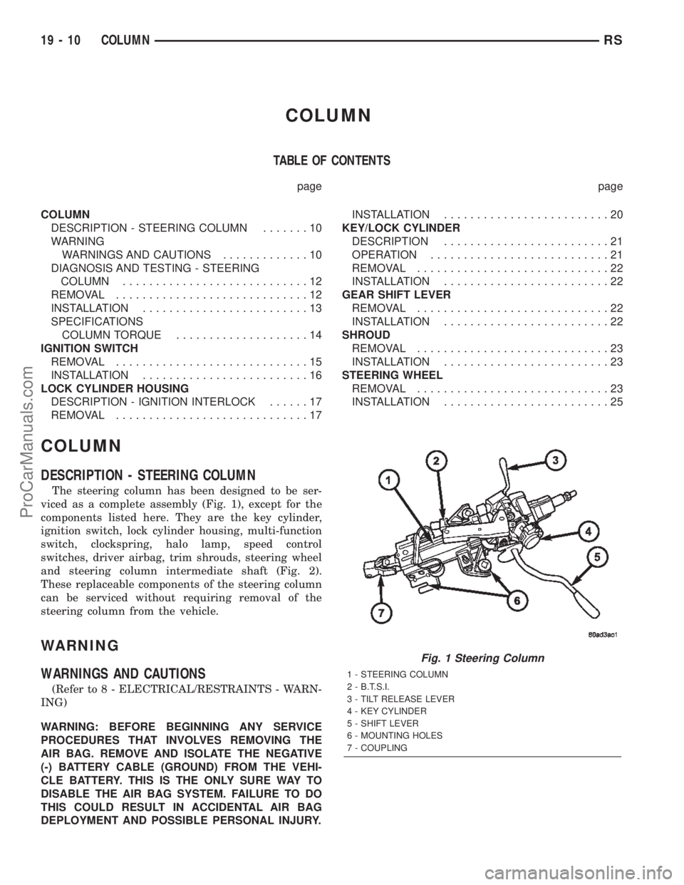
The steering column has been designed to be ser-
viced as a complete assembly (Fig. 1), except for the
components listed here. They are the key cylinder,
ignition switch, lock cylinder housing, multi-function
switch, clockspring, halo lamp, speed control
switches, driver airbag, trim shrouds, steering wheel
and steering column intermediate shaft (Fig. 2).
These replaceable components of the steering column
can be serviced without requiring removal of the
steering column from the vehicle.
WARNING
WARNINGS AND CAUTIONS
(Refer to 8 - ELECTRICAL/RESTRAINTS - WARN-
ING)
WARNING: BEFORE BEGINNING ANY SERVICE
PROCEDURES THAT INVOLVES REMOVING THE
AIR BAG. REMOVE AND ISOLATE THE NEGATIVE
(-) BATTERY CABLE (GROUND) FROM THE VEHI-
CLE BATTERY. THIS IS THE ONLY SURE WAY TO
DISABLE THE AIR BAG SYSTEM. FAILURE TO DO
THIS COULD RESULT IN ACCIDENTAL AIR BAG
DEPLOYMENT AND POSSIBLE PERSONAL INJURY.
Fig. 1 Steering Column
1 - STEERING COLUMN
2 - B.T.S.I.
3 - TILT RELEASE LEVER
4 - KEY CYLINDER
5 - SHIFT LEVER
6 - MOUNTING HOLES
7 - COUPLING
19 - 10 COLUMNRS
ProCarManuals.com
Page 1516 of 2399

(15) Disconnect the shift cable at the lever. (Fig. 4)
(16) Remove the pinch side clip, then remove the
cable from the bracket on the column.
(17) Remove the pinch bolt coupling. (Fig. 5)
(18) Loosen the two lower mounting nuts.
(19) Remove the two upper mounting nuts
(20) Remove the steering column.
(21) Remove the clockspring (Refer to 8 - ELEC-
TRICAL/RESTRAINTS/CLOCKSPRING - REMOV-
AL). (Fig. 6)
(22) Remove the mounting plate with the multi-
function switch.
(23) Remove the halo-lamp.(24) Remove the ignition key cylinder (Refer to 19
- STEERING/COLUMN/KEY/LOCK CYLINDER -
REMOVAL).
(25) Remove the BTSI.
INSTALLATION
To service the steering wheel components or the
airbag (Refer to 8 - ELECTRICAL/RESTRAINTS/
DRIVER AIRBAG - REMOVAL). Follow all WARN-
INGS AND CAUTIONS.
(1) Make sure the front wheels of the vehicle are
still in the STRAIGHT AHEAD position before begin-
ning the column installation procedure.
(2) Install the BTSI.
(3) Install the ignition key cylinder (Refer to 19 -
STEERING/COLUMN/KEY/LOCK CYLINDER -
INSTALLATION).
(4) Install the halo-lamp.
Fig. 3 STEERING WHEEL REMOVAL
1 - STEERING WHEEL
2 - PULLER
Fig. 4 SHIFT CABLE MOUNTING
1 - SHIFT CABLE MOUNT
2 - SHIFT LEVER
Fig. 5 PINCH BOLT
1 - PINCH BOLT
2 - STEERING COLUMN
Fig. 6 CLOCKSPRING
RSCOLUMN19-13
COLUMN (Continued)
ProCarManuals.com
Page 1519 of 2399
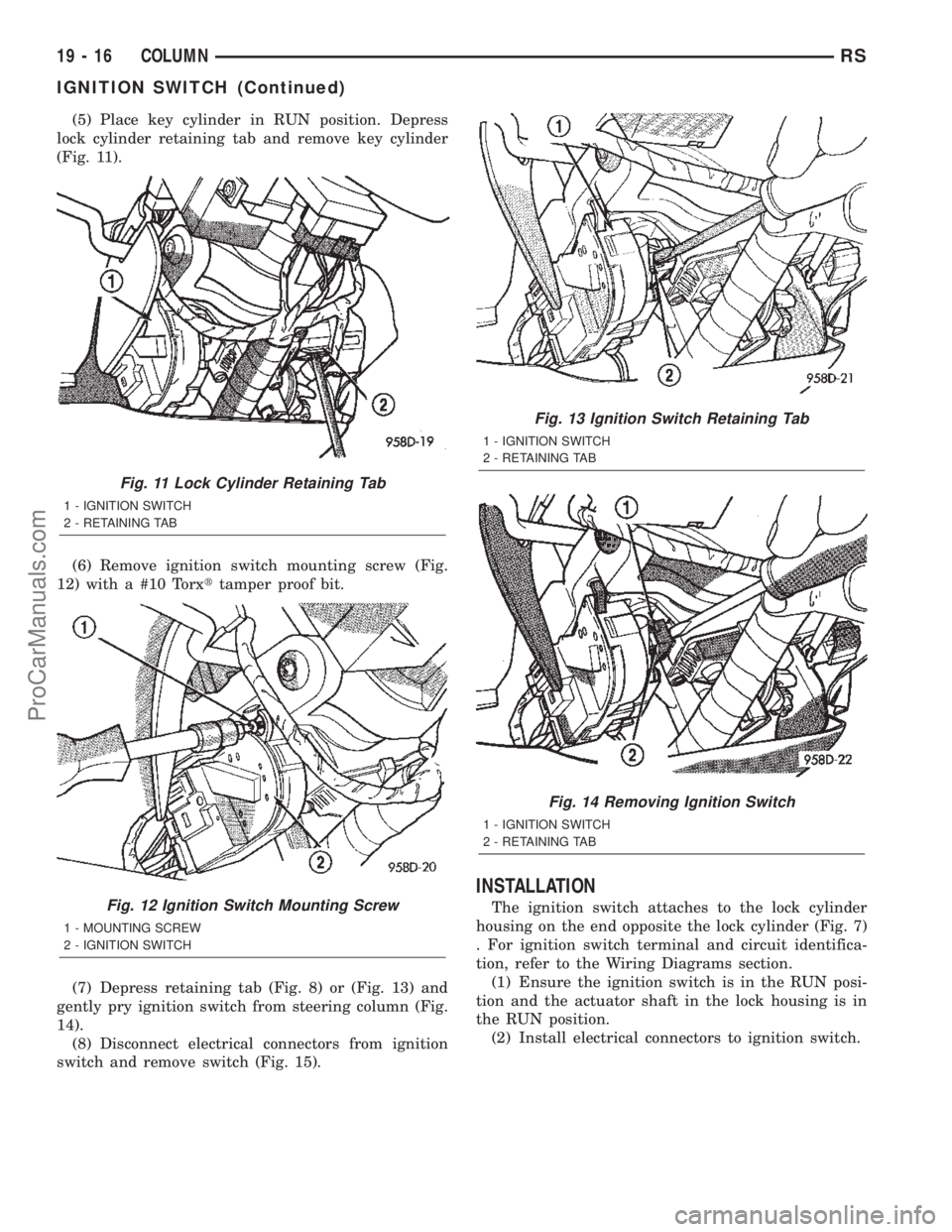
(5) Place key cylinder in RUN position. Depress
lock cylinder retaining tab and remove key cylinder
(Fig. 11).
(6) Remove ignition switch mounting screw (Fig.
12) with a #10 Torxttamper proof bit.
(7) Depress retaining tab (Fig. 8) or (Fig. 13) and
gently pry ignition switch from steering column (Fig.
14).
(8) Disconnect electrical connectors from ignition
switch and remove switch (Fig. 15).
INSTALLATION
The ignition switch attaches to the lock cylinder
housing on the end opposite the lock cylinder (Fig. 7)
. For ignition switch terminal and circuit identifica-
tion, refer to the Wiring Diagrams section.
(1) Ensure the ignition switch is in the RUN posi-
tion and the actuator shaft in the lock housing is in
the RUN position.
(2) Install electrical connectors to ignition switch.
Fig. 11 Lock Cylinder Retaining Tab
1 - IGNITION SWITCH
2 - RETAINING TAB
Fig. 12 Ignition Switch Mounting Screw
1 - MOUNTING SCREW
2 - IGNITION SWITCH
Fig. 13 Ignition Switch Retaining Tab
1 - IGNITION SWITCH
2 - RETAINING TAB
Fig. 14 Removing Ignition Switch
1 - IGNITION SWITCH
2 - RETAINING TAB
19 - 16 COLUMNRS
IGNITION SWITCH (Continued)
ProCarManuals.com
Page 1520 of 2399
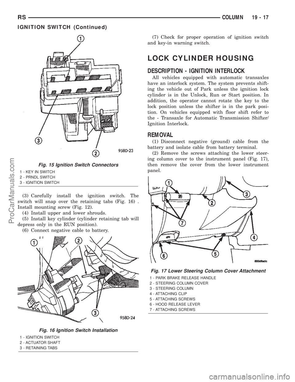
(3) Carefully install the ignition switch. The
switch will snap over the retaining tabs (Fig. 16) .
Install mounting screw (Fig. 12).
(4) Install upper and lower shrouds.
(5) Install key cylinder (cylinder retaining tab will
depress only in the RUN position).
(6) Connect negative cable to battery.(7) Check for proper operation of ignition switch
and key-in warning switch.
LOCK CYLINDER HOUSING
DESCRIPTION - IGNITION INTERLOCK
All vehicles equipped with automatic transaxles
have an interlock system. The system prevents shift-
ing the vehicle out of Park unless the ignition lock
cylinder is in the Unlock, Run or Start position. In
addition, the operator cannot rotate the key to the
lock position unless the shifter is in the park posi-
tion. On vehicles equipped with floor shift refer to
the - Transaxle for Automatic Transmission Shifter/
Ignition Interlock.
REMOVAL
(1) Disconnect negative (ground) cable from the
battery and isolate cable from battery terminal.
(2) Remove the screws attaching the lower steer-
ing column cover to the instrument panel (Fig. 17),
then remove the cover from the lower instrument
panel.
Fig. 15 Ignition Switch Connectors
1 - KEY IN SWITCH
2 - PRNDL SWITCH
3 - IGNITION SWITCH
Fig. 16 Ignition Switch Installation
1 - IGNITION SWITCH
2 - ACTUATOR SHAFT
3 - RETAINING TABS
Fig. 17 Lower Steering Column Cover Attachment
1 - PARK BRAKE RELEASE HANDLE
2 - STEERING COLUMN COVER
3 - STEERING COLUMN
4 - ATTACHING CLIP
5 - ATTACHING SCREWS
6 - HOOD RELEASE LEVER
7 - ATTACHING SCREWS
RSCOLUMN19-17
IGNITION SWITCH (Continued)
ProCarManuals.com
Page 1522 of 2399
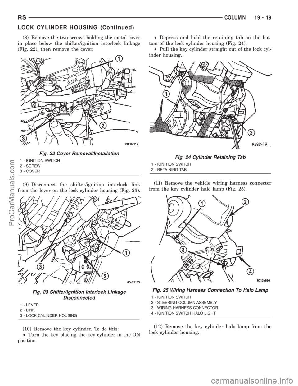
(8) Remove the two screws holding the metal cover
in place below the shifter/ignition interlock linkage
(Fig. 22), then remove the cover.
(9) Disconnect the shifter/ignition interlock link
from the lever on the lock cylinder housing (Fig. 23).
(10) Remove the key cylinder. To do this:
²Turn the key placing the key cylinder in the ON
position.²Depress and hold the retaining tab on the bot-
tom of the lock cylinder housing (Fig. 24).
²Pull the key cylinder straight out of the lock cyl-
inder housing.
(11) Remove the vehicle wiring harness connector
from the key cylinder halo lamp (Fig. 25).
(12) Remove the key cylinder halo lamp from the
lock cylinder housing.
Fig. 22 Cover Removal/Installation
1 - IGNITION SWITCH
2 - SCREW
3 - COVER
Fig. 23 Shifter/Ignition Interlock Linkage
Disconnected
1 - LEVER
2 - LINK
3 - LOCK CYLINDER HOUSING
Fig. 24 Cylinder Retaining Tab
1 - IGNITION SWITCH
2 - RETAINING TAB
Fig. 25 Wiring Harness Connection To Halo Lamp
1 - IGNITION SWITCH
2 - STEERING COLUMN ASSEMBLY
3 - WIRING HARNESS CONNECTOR
4 - IGNITION SWITCH HALO LIGHT
RSCOLUMN19-19
LOCK CYLINDER HOUSING (Continued)
ProCarManuals.com
Page 1524 of 2399
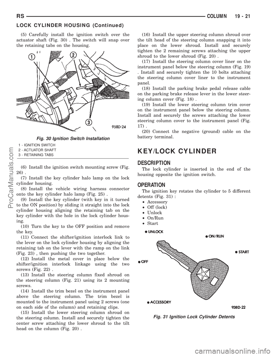
(5) Carefully install the ignition switch over the
actuator shaft (Fig. 30) . The switch will snap over
the retaining tabs on the housing.
(6) Install the ignition switch mounting screw (Fig.
26) .
(7) Install the key cylinder halo lamp on the lock
cylinder housing.
(8) Install the vehicle wiring harness connector
onto the key cylinder halo lamp (Fig. 25) .
(9) Install the key cylinder (with key in it turned
to the ON position) by sliding it straight into the lock
cylinder housing aligning the retaining tab on the
key cylinder with the hole in the lock cylinder hous-
ing.
(10) Turn the key to the OFF position and remove
the key.
(11) Connect the shifter/ignition interlock link to
the lever on the lock cylinder housing by aligning the
retaining tab on the lever with the ramp on the link
(Fig. 23) , then pushing the two together.
(12) Install the metal cover in place below the
shifter/ignition interlock linkage using the two
screws (Fig. 22) .
(13) Install the steering column fixed shroud on
the steering column (Fig. 21) using its 2 mounting
screws.
(14) Install the trim bezel on the instrument panel
above the steering column. The trim bezel is
mounted to the instrument panel using 2 screws (one
on each side of the column) and retaining clips.
(15) Install the lower steering column shroud on
the steering column. Install and securely tighten the
center screw attaching the lower shroud to the tilt
head on the column (Fig. 20) .(16) Install the upper steering column shroud over
the tilt head of the steering column snapping it into
place on the lower shroud. Install and securely
tighten the 2 remaining screws attaching the upper
shroud to the lower shroud (Fig. 20) .
(17) Install the steering column cover liner on the
instrument panel below the steering column (Fig. 19)
. Install and securely tighten the 10 bolts attaching
the steering column cover liner to the instrument
panel.
(18) Install the parking brake pedal release cable
on the parking brake release lever in the lower steer-
ing column cover (Fig. 18) .
(19) Install the lower steering column trim cover
on the instrument panel below the steering column.
Install and securely the screws attaching the lower
steering column cover to the instrument panel (Fig.
17) .
(20) Connect the negative (ground) cable on the
battery terminal.
KEY/LOCK CYLINDER
DESCRIPTION
The lock cylinder is inserted in the end of the
housing opposite the ignition switch.
OPERATION
The ignition key rotates the cylinder to 5 different
detents (Fig. 31) :
²Accessory
²Off (lock)
²Unlock
²On/Run
²Start
Fig. 30 Ignition Switch Installation
1 - IGNITION SWITCH
2 - ACTUATOR SHAFT
3 - RETAINING TABS
Fig. 31 Ignition Lock Cylinder Detents
RSCOLUMN19-21
LOCK CYLINDER HOUSING (Continued)
ProCarManuals.com
Page 1525 of 2399
REMOVAL
(1) Disconnect negative cable from battery.
(2) Remove steering column cover retaining
screws.
(3) Remove screws holding steering column
shrouds and remove lower shroud.
(4) Place key cylinder in RUN position. Depress
lock cylinder retaining tab on the bottom of the lock
housing and remove key cylinder.
INSTALLATION
(1) Install key in lock cylinder. Turn key to run
position (retaining tab on lock cylinder can be
depressed).
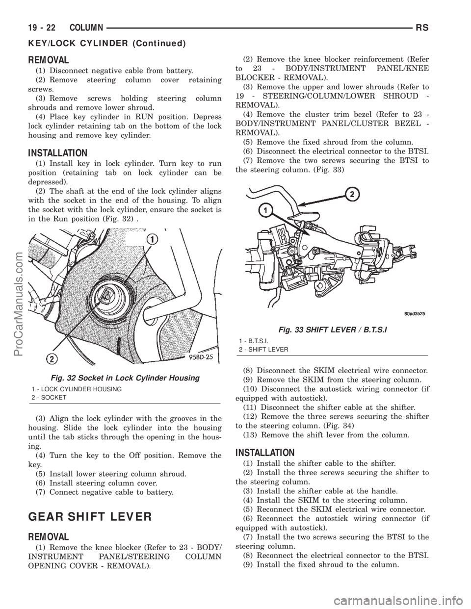
(2) The shaft at the end of the lock cylinder aligns
with the socket in the end of the housing. To align
the socket with the lock cylinder, ensure the socket is
in the Run position (Fig. 32) .
(3) Align the lock cylinder with the grooves in the
housing. Slide the lock cylinder into the housing
until the tab sticks through the opening in the hous-
ing.
(4) Turn the key to the Off position. Remove the
key.
(5) Install lower steering column shroud.
(6) Install steering column cover.
(7) Connect negative cable to battery.
GEAR SHIFT LEVER
REMOVAL
(1) Remove the knee blocker (Refer to 23 - BODY/
INSTRUMENT PANEL/STEERING COLUMN
OPENING COVER - REMOVAL).(2) Remove the knee blocker reinforcement (Refer
to 23 - BODY/INSTRUMENT PANEL/KNEE
BLOCKER - REMOVAL).
(3) Remove the upper and lower shrouds (Refer to
19 - STEERING/COLUMN/LOWER SHROUD -
REMOVAL).
(4) Remove the cluster trim bezel (Refer to 23 -
BODY/INSTRUMENT PANEL/CLUSTER BEZEL -
REMOVAL).
(5) Remove the fixed shroud from the column.
(6) Disconnect the electrical connector to the BTSI.
(7) Remove the two screws securing the BTSI to
the steering column. (Fig. 33)
(8) Disconnect the SKIM electrical wire connector.
(9) Remove the SKIM from the steering column.
(10) Disconnect the autostick wiring connector (if
equipped with autostick).
(11) Disconnect the shifter cable at the shifter.
(12) Remove the three screws securing the shifter
to the steering column. (Fig. 34)
(13) Remove the shift lever from the column.
INSTALLATION
(1) Install the shifter cable to the shifter.
(2) Install the three screws securing the shifter to
the steering column.
(3) Install the shifter cable at the handle.
(4) Install the SKIM to the steering column.
(5) Reconnect the SKIM electrical wire connector.
(6) Reconnect the autostick wiring connector (if
equipped with autostick).
(7) Install the two screws securing the BTSI to the
steering column.
(8) Reconnect the electrical connector to the BTSI.
(9) Install the fixed shroud to the column.
Fig. 32 Socket in Lock Cylinder Housing
1 - LOCK CYLINDER HOUSING
2 - SOCKET
Fig. 33 SHIFT LEVER / B.T.S.I
1 - B.T.S.I.
2 - SHIFT LEVER
19 - 22 COLUMNRS
KEY/LOCK CYLINDER (Continued)
ProCarManuals.com
Page 1526 of 2399
(10) Install the cluster trim bezel (Refer to 23 -
BODY/INSTRUMENT PANEL/CLUSTER BEZEL -
INSTALLATION).
(11) Install the upper and lower shrouds (Refer to
19 - STEERING/COLUMN/LOWER SHROUD -
INSTALLATION).
(12) Install the knee blocker reinforcement (Refer
to 23 - BODY/INSTRUMENT PANEL/KNEE
BLOCKER - INSTALLATION).
(13) Install the knee blocker (Refer to 23 - BODY/
INSTRUMENT PANEL/STEERING COLUMN
OPENING COVER - INSTALLATION).
SHROUD
REMOVAL
(1) Remove the three screws from the lower
shroud.
(2) Unsnap and remove the lower shroud.
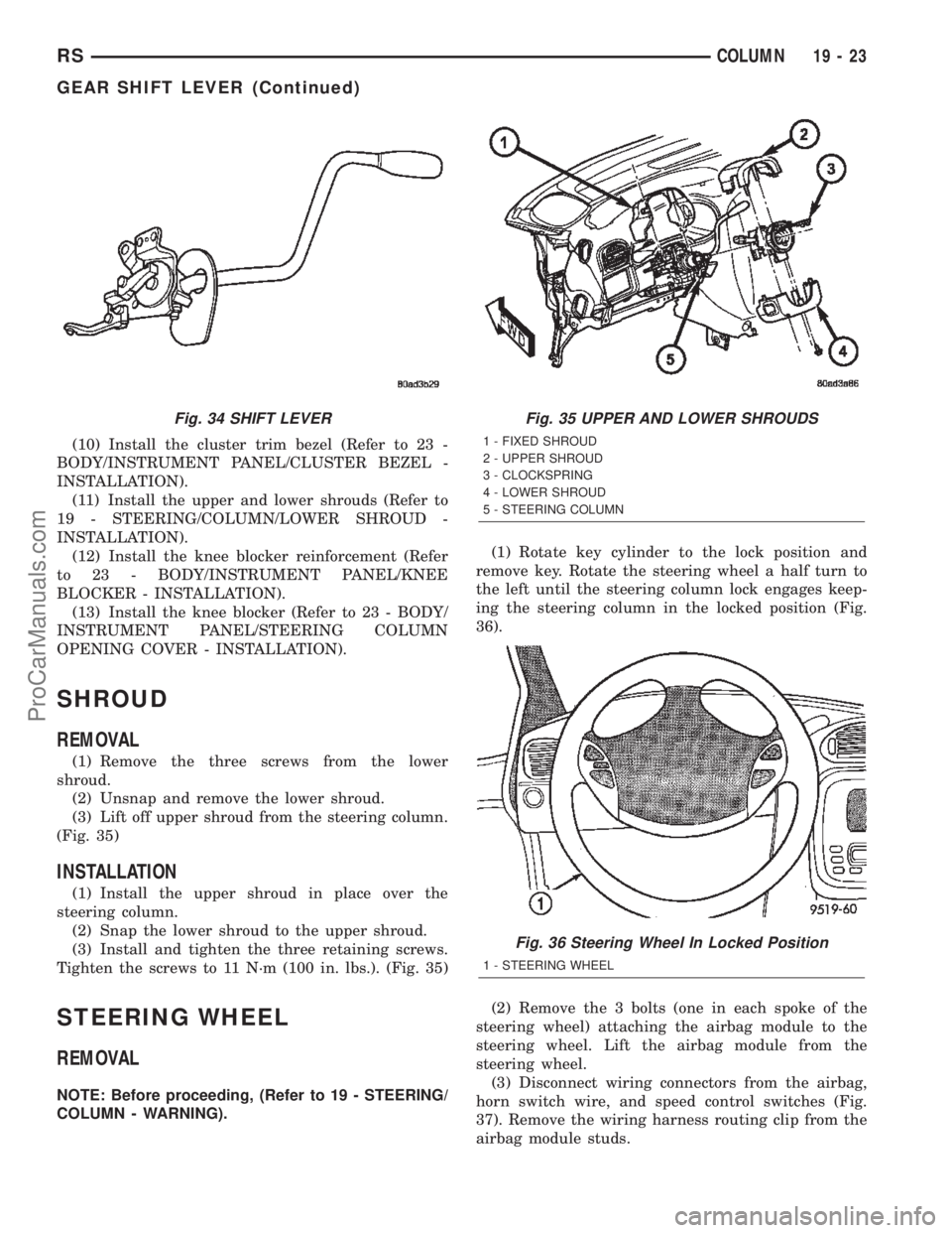
(3) Lift off upper shroud from the steering column.
(Fig. 35)
INSTALLATION
(1) Install the upper shroud in place over the
steering column.
(2) Snap the lower shroud to the upper shroud.
(3) Install and tighten the three retaining screws.
Tighten the screws to 11 N´m (100 in. lbs.). (Fig. 35)
STEERING WHEEL
REMOVAL
NOTE: Before proceeding, (Refer to 19 - STEERING/
COLUMN - WARNING).(1) Rotate key cylinder to the lock position and
remove key. Rotate the steering wheel a half turn to
the left until the steering column lock engages keep-
ing the steering column in the locked position (Fig.
36).
(2) Remove the 3 bolts (one in each spoke of the
steering wheel) attaching the airbag module to the
steering wheel. Lift the airbag module from the
steering wheel.
(3) Disconnect wiring connectors from the airbag,
horn switch wire, and speed control switches (Fig.
37). Remove the wiring harness routing clip from the
airbag module studs.
Fig. 34 SHIFT LEVERFig. 35 UPPER AND LOWER SHROUDS
1 - FIXED SHROUD
2 - UPPER SHROUD
3 - CLOCKSPRING
4 - LOWER SHROUD
5 - STEERING COLUMN
Fig. 36 Steering Wheel In Locked Position
1 - STEERING WHEEL
RSCOLUMN19-23
GEAR SHIFT LEVER (Continued)
ProCarManuals.com