2002 CHRYSLER CARAVAN turn signal
[x] Cancel search: turn signalPage 1153 of 2399
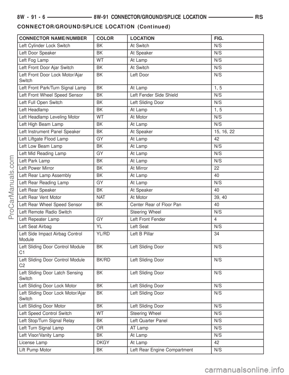
CONNECTOR NAME/NUMBER COLOR LOCATION FIG.
Left Cylinder Lock Switch BK At Switch N/S
Left Door Speaker BK At Speaker N/S
Left Fog Lamp WT At Lamp N/S
Left Front Door Ajar Switch BK At Switch N/S
Left Front Door Lock Motor/Ajar
SwitchBK Left Door N/S
Left Front Park/Turn Signal Lamp BK At Lamp 1, 5
Left Front Wheel Speed Sensor BK Left Fender Side Shield N/S
Left Full Open Switch BK Left Sliding Door N/S
Left Headlamp BK At Lamp 1, 5
Left Headlamp Leveling Motor WT At Motor N/S
Left High Beam Lamp BK At Lamp N/S
Left Instrument Panel Speaker BK At Speaker 15, 16, 22
Left Liftgate Flood Lamp GY At Lamp 42
Left Low Beam Lamp BK At Lamp N/S
Left Mid Reading Lamp GY At Lamp N/S
Left Park Lamp BK At Lamp N/S
Left Power Mirror BK At Mirror 22
Left Rear Lamp Assembly BK At Lamp 40
Left Rear Reading Lamp GY At Lamp N/S
Left Rear Speaker BK At Speaker 40
Left Rear Vent Motor NAT At Motor 39, 40
Left Rear Wheel Speed Sensor BK Center Rear of Floor Pan 40
Left Remote Radio Switch Steering Wheel N/S
Left Repeater Lamp GY Left Front Fender 4
Left Seat Airbag YL Left Seat N/S
Left Side Impact Airbag Control
ModuleYL/RD Left B Pillar 34
Left Sliding Door Control Module
C1BK Left Sliding Door N/S
Left Sliding Door Control Module
C2BK/RD Left Sliding Door N/S
Left Sliding Door Latch Sensing
SwitchBK Left Sliding Door N/S
Left Sliding Door Lock Motor BK Left Sliding Door N/S
Left Sliding Door Lock Motor/Ajar
SwitchBK Left Sliding Door N/S
Left Sliding Door Motor BK Left Sliding Door N/S
Left Speed Control Switch WT Steering Wheel N/S
Left Stop/Turn Signal Relay BK Left Quarter Panel N/S
Left Turn Signal Lamp OR AT Lamp N/S
Left Visor/Vanity Lamp BK At Lamp N/S
License Lamp DKGY At Lamp 42
Lift Pump Motor BK Left Rear Engine Compartment N/S
8W - 91 - 6 8W-91 CONNECTOR/GROUND/SPLICE LOCATIONRS
CONNECTOR/GROUND/SPLICE LOCATION (Continued)
ProCarManuals.com
Page 1156 of 2399
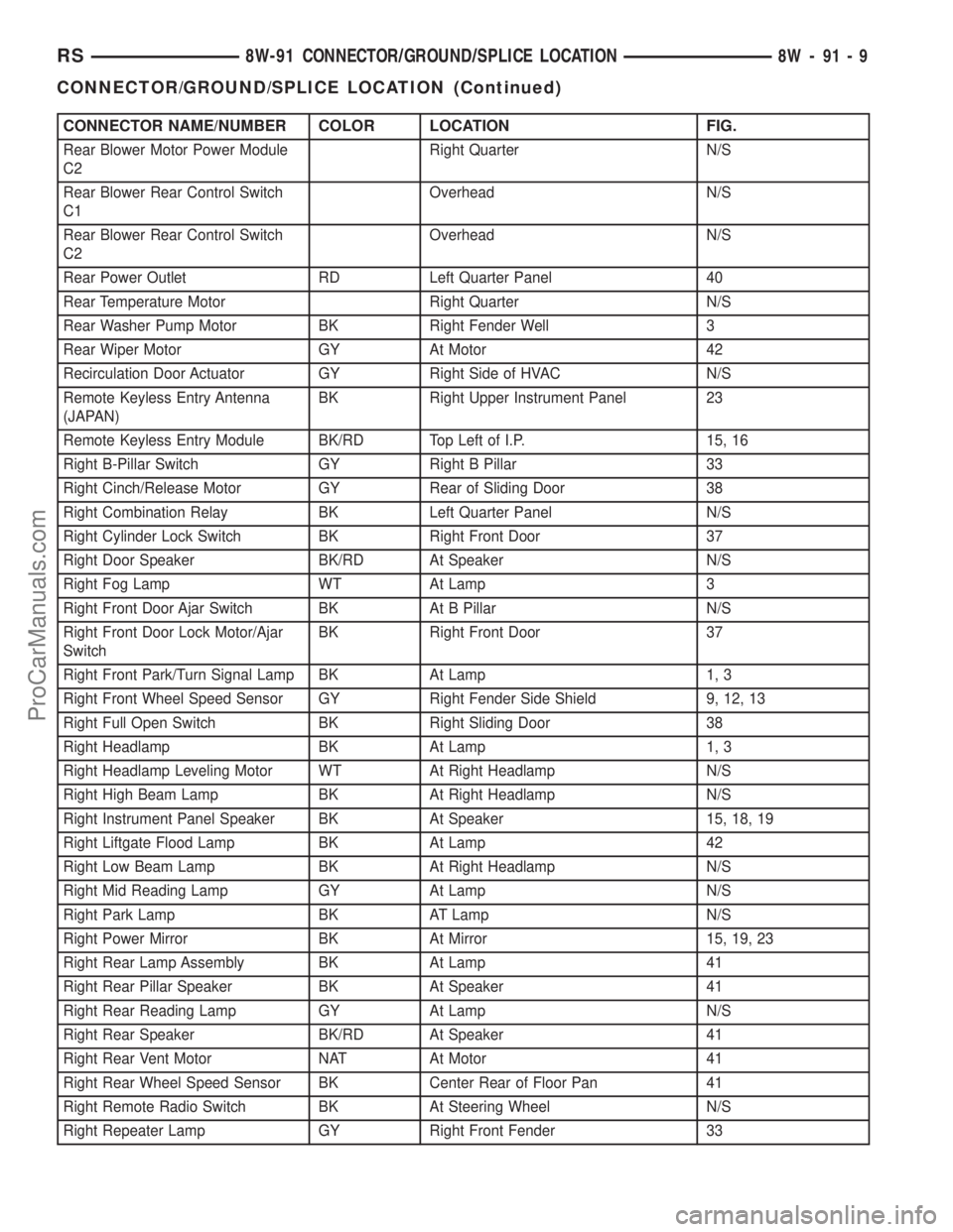
CONNECTOR NAME/NUMBER COLOR LOCATION FIG.
Rear Blower Motor Power Module
C2Right Quarter N/S
Rear Blower Rear Control Switch
C1Overhead N/S
Rear Blower Rear Control Switch
C2Overhead N/S
Rear Power Outlet RD Left Quarter Panel 40
Rear Temperature Motor Right Quarter N/S
Rear Washer Pump Motor BK Right Fender Well 3
Rear Wiper Motor GY At Motor 42
Recirculation Door Actuator GY Right Side of HVAC N/S
Remote Keyless Entry Antenna
(JAPAN)BK Right Upper Instrument Panel 23
Remote Keyless Entry Module BK/RD Top Left of I.P. 15, 16
Right B-Pillar Switch GY Right B Pillar 33
Right Cinch/Release Motor GY Rear of Sliding Door 38
Right Combination Relay BK Left Quarter Panel N/S
Right Cylinder Lock Switch BK Right Front Door 37
Right Door Speaker BK/RD At Speaker N/S
Right Fog Lamp WT At Lamp 3
Right Front Door Ajar Switch BK At B Pillar N/S
Right Front Door Lock Motor/Ajar
SwitchBK Right Front Door 37
Right Front Park/Turn Signal Lamp BK At Lamp 1, 3
Right Front Wheel Speed Sensor GY Right Fender Side Shield 9, 12, 13
Right Full Open Switch BK Right Sliding Door 38
Right Headlamp BK At Lamp 1, 3
Right Headlamp Leveling Motor WT At Right Headlamp N/S
Right High Beam Lamp BK At Right Headlamp N/S
Right Instrument Panel Speaker BK At Speaker 15, 18, 19
Right Liftgate Flood Lamp BK At Lamp 42
Right Low Beam Lamp BK At Right Headlamp N/S
Right Mid Reading Lamp GY At Lamp N/S
Right Park Lamp BK AT Lamp N/S
Right Power Mirror BK At Mirror 15, 19, 23
Right Rear Lamp Assembly BK At Lamp 41
Right Rear Pillar Speaker BK At Speaker 41
Right Rear Reading Lamp GY At Lamp N/S
Right Rear Speaker BK/RD At Speaker 41
Right Rear Vent Motor NAT At Motor 41
Right Rear Wheel Speed Sensor BK Center Rear of Floor Pan 41
Right Remote Radio Switch BK At Steering Wheel N/S
Right Repeater Lamp GY Right Front Fender 33
RS8W-91 CONNECTOR/GROUND/SPLICE LOCATION8W-91-9
CONNECTOR/GROUND/SPLICE LOCATION (Continued)
ProCarManuals.com
Page 1157 of 2399
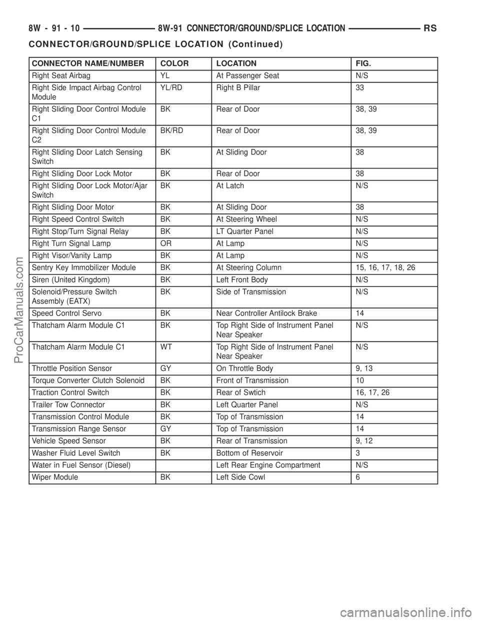
CONNECTOR NAME/NUMBER COLOR LOCATION FIG.
Right Seat Airbag YL At Passenger Seat N/S
Right Side Impact Airbag Control
ModuleYL/RD Right B Pillar 33
Right Sliding Door Control Module
C1BK Rear of Door 38, 39
Right Sliding Door Control Module
C2BK/RD Rear of Door 38, 39
Right Sliding Door Latch Sensing
SwitchBK At Sliding Door 38
Right Sliding Door Lock Motor BK Rear of Door 38
Right Sliding Door Lock Motor/Ajar
SwitchBK At Latch N/S
Right Sliding Door Motor BK At Sliding Door 38
Right Speed Control Switch BK At Steering Wheel N/S
Right Stop/Turn Signal Relay BK LT Quarter Panel N/S
Right Turn Signal Lamp OR At Lamp N/S
Right Visor/Vanity Lamp BK At Lamp N/S
Sentry Key Immobilizer Module BK At Steering Column 15, 16, 17, 18, 26
Siren (United Kingdom) BK Left Front Body N/S
Solenoid/Pressure Switch
Assembly (EATX)BK Side of Transmission N/S
Speed Control Servo BK Near Controller Antilock Brake 14
Thatcham Alarm Module C1 BK Top Right Side of Instrument Panel
Near SpeakerN/S
Thatcham Alarm Module C1 WT Top Right Side of Instrument Panel
Near SpeakerN/S
Throttle Position Sensor GY On Throttle Body 9, 13
Torque Converter Clutch Solenoid BK Front of Transmission 10
Traction Control Switch BK Rear of Swtich 16, 17, 26
Trailer Tow Connector BK Left Quarter Panel N/S
Transmission Control Module BK Top of Transmission 14
Transmission Range Sensor GY Top of Transmission 14
Vehicle Speed Sensor BK Rear of Transmission 9, 12
Washer Fluid Level Switch BK Bottom of Reservoir 3
Water in Fuel Sensor (Diesel) Left Rear Engine Compartment N/S
Wiper Module BK Left Side Cowl 6
8W - 91 - 10 8W-91 CONNECTOR/GROUND/SPLICE LOCATIONRS
CONNECTOR/GROUND/SPLICE LOCATION (Continued)
ProCarManuals.com
Page 1436 of 2399
bearing housing, routes the engine oil back to the
crankcase.
The most common turbocharger failure is bearing
failure related to repeated hot shutdowns with inad-
equate ªcool-downº periods. A sudden engine shut
down after prolonged operation will result in the
transfer of heat from the turbine section of the tur-
bocharger to the bearing housing. This causes the oil
to overheat and break down, which causes bearing
and shaft damage the next time the vehicle is
started.Letting the engine idle after extended operation
allows the turbine housing to cool to normal operat-
ing temperature. The following chart should be used
as a guide in determining the amount of engine idle
time required to sufficiently cool down the turbo-
charger before shut down, depending upon the type
of driving and the amount of cargo.
TURBOCHARGER(COOL DOWN(CHART
Driving Load Turbocharger Idle Time
(in
minuetes)
Condition Temperature Before
Shut Down
Stop & Go Empty Cool Less than 1
Stop & Go Medium Warm 1
Highway
SpeedsMedium Warm 2
City Traffic Max.
GCWRWarm 3
Highway
SpeedsMax.
GCWRWarm 4
Uphill
GradeMax.
GCWRHot 5
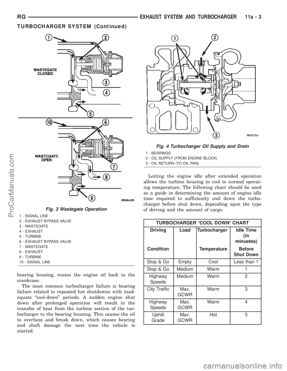
Fig. 3 Wastegate Operation
1 - SIGNAL LINE
2 - EXHAUST BYPASS VALVE
3 - WASTEGATE
4 - EXHAUST
5 - TURBINE
6 - EXHAUST BYPASS VALVE
7 - WASTEGATE
8 - EXHAUST
9 - TURBINE
10 - SIGNAL LINE
Fig. 4 Turbocharger Oil Supply and Drain
1 - BEARINGS
2 - OIL SUPPLY (FROM ENGINE BLOCK)
3 - OIL RETURN (TO OIL PAN)
RGEXHAUST SYSTEM AND TURBOCHARGER11a-3
TURBOCHARGER SYSTEM (Continued)
ProCarManuals.com
Page 1469 of 2399
1 second. Therefore, battery voltage is not supplied to
the fuel pump, ignition coil, fuel injectors and heated
oxygen sensors.
ENGINE START-UP MODE
This is an OPEN LOOP mode. If the vehicle is in
park or neutral (automatic transaxles) or the clutch
pedal is depressed (manual transaxles) the ignition
switch energizes the starter relay. The following
actions occur when the starter motor is engaged.
²If the PCM receives the camshaft position sensor
and crankshaft position sensor signals, it energizes
the Auto Shutdown (ASD) relay and fuel pump relay.
If the PCM does not receive both signals within
approximately one second, it will not energize the
ASD relay and fuel pump relay. The ASD and fuel
pump relays supply battery voltage to the fuel pump,
fuel injectors, ignition coil, (EGR solenoid and PCV
heater if equipped) and heated oxygen sensors.
²The PCM energizes the injectors (on the 69É
degree falling edge) for a calculated pulse width until
it determines crankshaft position from the camshaft
position sensor and crankshaft position sensor sig-
nals. The PCM determines crankshaft position within
1 engine revolution.
²After determining crankshaft position, the PCM
begins energizing the injectors in sequence. It adjusts
injector pulse width and controls injector synchroni-
zation by turning the individual ground paths to the
injectors On and Off.
²When the engine idles within 64 RPM of its
target RPM, the PCM compares current MAP sensor
value with the atmospheric pressure value received
during the Ignition Switch On (zero RPM) mode.
Once the ASD and fuel pump relays have been
energized, the PCM determines injector pulse width
based on the following:
²MAP
²Engine RPM
²Battery voltage
²Engine coolant temperature
²Inlet/Intake air temperature (IAT)
²Throttle position
²The number of engine revolutions since cranking
was initiated
During Start-up the PCM maintains ignition tim-
ing at 9É BTDC.
ENGINE WARM-UP MODE
This is an OPEN LOOP mode. The following inputs
are received by the PCM:
²Manifold Absolute Pressure (MAP)
²Crankshaft position (engine speed)
²Engine coolant temperature
²Inlet/Intake air temperature (IAT)
²Camshaft position²Knock sensor
²Throttle position
²A/C switch
²Battery voltage
²Vehicle speed
²Speed control
²O2 sensors
The PCM adjusts injector pulse width and controls
injector synchronization by turning the individual
ground paths to the injectors On and Off.
The PCM adjusts ignition timing and engine idle
speed. Engine idle speed is adjusted through the idle
air control motor.
CRUISE OR IDLE MODE
When the engine is at operating temperature this
is a CLOSED LOOP mode. During cruising or idle
the following inputs are received by the PCM:
²Manifold absolute pressure
²Crankshaft position (engine speed)
²Inlet/Intake air temperature
²Engine coolant temperature
²Camshaft position
²Knock sensor
²Throttle position
²Exhaust gas oxygen content
²A/C control positions
²Battery voltage
²Vehicle speed
The PCM adjusts injector pulse width and controls
injector synchronization by turning the individual
ground paths to the injectors On and Off.
The PCM adjusts engine idle speed and ignition
timing. The PCM adjusts the air/fuel ratio according
to the oxygen content in the exhaust gas (measured
by the upstream and downstream heated oxygen sen-
sor).
The PCM monitors for engine misfire. During
active misfire and depending on the severity, the
PCM either continuously illuminates or flashes the
malfunction indicator lamp (Check Engine light on
instrument panel). Also, the PCM stores an engine
misfire DTC in memory, if 2nd trip with fault.
The PCM performs several diagnostic routines.
They include:
²Oxygen sensor monitor
²Downstream heated oxygen sensor diagnostics
during open loop operation (except for shorted)
²Fuel system monitor
²EGR monitor (if equipped)
²Purge system monitor
²Catalyst efficiency monitor
²All inputs monitored for proper voltage range,
rationality.
²All monitored components (refer to the Emission
section for On-Board Diagnostics).
14 - 18 FUEL INJECTIONRS
FUEL INJECTION (Continued)
ProCarManuals.com
Page 1480 of 2399
age will be higher at colder temperatures and is
gradually reduced at warmer temperatures.
The battery temperature information is also used
for OBD II diagnostics. Certain faults and OBD II
monitors are either enabled or disabled depending
upon the battery temperature sensor input (example:
disable purge, enable LDP). Most OBD II monitors
are disabled below 20ÉF.
MAP SENSOR
DESCRIPTION
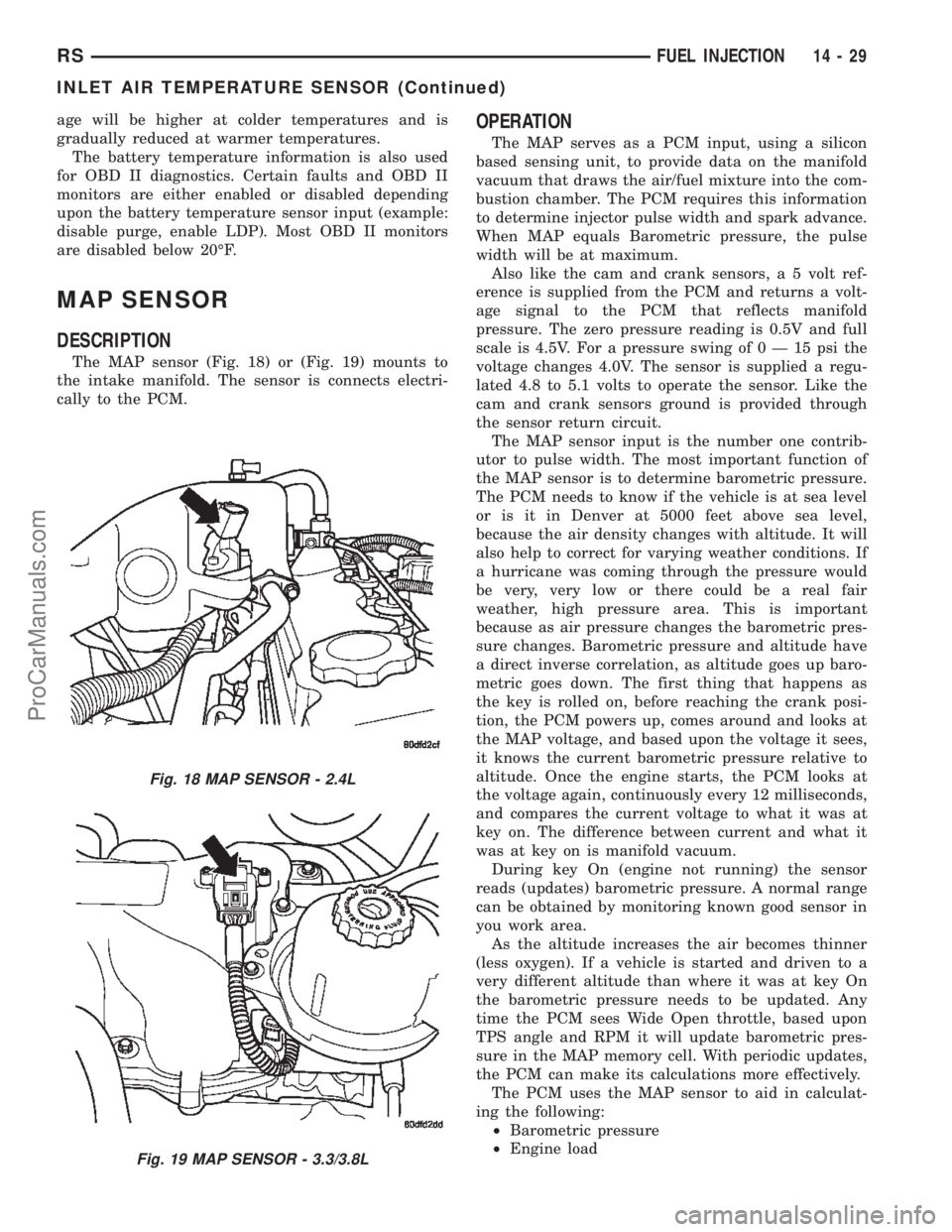
The MAP sensor (Fig. 18) or (Fig. 19) mounts to
the intake manifold. The sensor is connects electri-
cally to the PCM.
OPERATION
The MAP serves as a PCM input, using a silicon
based sensing unit, to provide data on the manifold
vacuum that draws the air/fuel mixture into the com-
bustion chamber. The PCM requires this information
to determine injector pulse width and spark advance.
When MAP equals Barometric pressure, the pulse
width will be at maximum.
Also like the cam and crank sensors, a 5 volt ref-
erence is supplied from the PCM and returns a volt-
age signal to the PCM that reflects manifold
pressure. The zero pressure reading is 0.5V and full
scale is 4.5V. For a pressure swing of0Ð15psithe
voltage changes 4.0V. The sensor is supplied a regu-
lated 4.8 to 5.1 volts to operate the sensor. Like the
cam and crank sensors ground is provided through
the sensor return circuit.
The MAP sensor input is the number one contrib-
utor to pulse width. The most important function of
the MAP sensor is to determine barometric pressure.
The PCM needs to know if the vehicle is at sea level
or is it in Denver at 5000 feet above sea level,
because the air density changes with altitude. It will
also help to correct for varying weather conditions. If
a hurricane was coming through the pressure would
be very, very low or there could be a real fair
weather, high pressure area. This is important
because as air pressure changes the barometric pres-
sure changes. Barometric pressure and altitude have
a direct inverse correlation, as altitude goes up baro-
metric goes down. The first thing that happens as
the key is rolled on, before reaching the crank posi-
tion, the PCM powers up, comes around and looks at
the MAP voltage, and based upon the voltage it sees,
it knows the current barometric pressure relative to
altitude. Once the engine starts, the PCM looks at
the voltage again, continuously every 12 milliseconds,
and compares the current voltage to what it was at
key on. The difference between current and what it
was at key on is manifold vacuum.
During key On (engine not running) the sensor
reads (updates) barometric pressure. A normal range
can be obtained by monitoring known good sensor in
you work area.
As the altitude increases the air becomes thinner
(less oxygen). If a vehicle is started and driven to a
very different altitude than where it was at key On
the barometric pressure needs to be updated. Any
time the PCM sees Wide Open throttle, based upon
TPS angle and RPM it will update barometric pres-
sure in the MAP memory cell. With periodic updates,
the PCM can make its calculations more effectively.
The PCM uses the MAP sensor to aid in calculat-
ing the following:
²Barometric pressure
²Engine load
Fig. 18 MAP SENSOR - 2.4L
Fig. 19 MAP SENSOR - 3.3/3.8L
RSFUEL INJECTION14-29
INLET AIR TEMPERATURE SENSOR (Continued)
ProCarManuals.com
Page 1497 of 2399
(6) Using special tool VM.1055 (Fig. 7), torque
injection pump sprocket retaining nut to 88.3N´m.
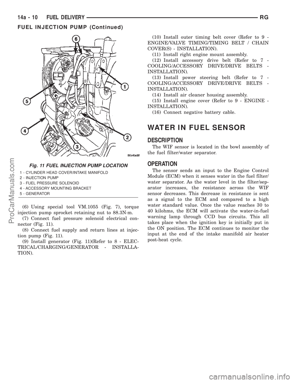
(7) Connect fuel pressure solenoid electrical con-
nector (Fig. 11).
(8) Connect fuel supply and return lines at injec-
tion pump (Fig. 11).
(9) Install generator (Fig. 11)(Refer to 8 - ELEC-
TRICAL/CHARGING/GENERATOR - INSTALLA-
TION).(10) Install outer timing belt cover (Refer to 9 -
ENGINE/VALVE TIMING/TIMING BELT / CHAIN
COVER(S) - INSTALLATION).
(11) Install right engine mount assembly.
(12) Install accessory drive belt (Refer to 7 -
COOLING/ACCESSORY DRIVE/DRIVE BELTS -
INSTALLATION).
(13) Install power steering belt (Refer to 7 -
COOLING/ACCESSORY DRIVE/DRIVE BELTS -
INSTALLATION).
(14) Install air cleaner housing assembly.
(15) Install engine cover (Refer to 9 - ENGINE -
INSTALLATION).
(16) Connect negative battery cable.
WATER IN FUEL SENSOR
DESCRIPTION
The WIF sensor is located in the bowl assembly of
the fuel filter/water separator.
OPERATION
The sensor sends an input to the Engine Control
Module (ECM) when it senses water in the fuel filter/
water separator. As the water level in the filter/sep-
arator increases, the resistance across the WIF
sensor decreases. This decrease in resistance is sent
as a signal to the ECM and compared to a high
water standard value. Once the value reaches 30 to
40 kilohms, the ECM will activate the water-in-fuel
warning lamp through CCD bus circuits. This all
takes place when the ignition key is initially put in
the ON position. The ECM continues to monitor the
input at the end of the intake manifold air heater
post-heat cycle.
Fig. 11 FUEL INJECTION PUMP LOCATION
1 - CYLINDER HEAD COVER/INTAKE MANIFOLD
2 - INJECTION PUMP
3 - FUEL PRESSURE SOLENOID
4 - ACCESSORY MOUNTING BRACKET
5 - GENERATOR
14a - 10 FUEL DELIVERYRG
FUEL INJECTION PUMP (Continued)
ProCarManuals.com
Page 1500 of 2399
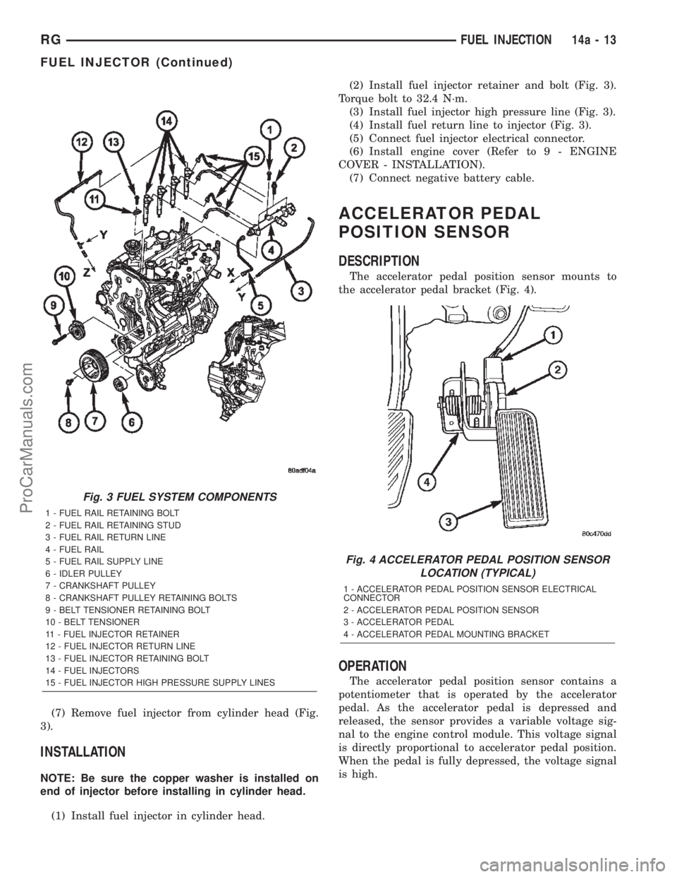
(7) Remove fuel injector from cylinder head (Fig.
3).
INSTALLATION
NOTE: Be sure the copper washer is installed on
end of injector before installing in cylinder head.
(1) Install fuel injector in cylinder head.(2) Install fuel injector retainer and bolt (Fig. 3).
Torque bolt to 32.4 N´m.
(3) Install fuel injector high pressure line (Fig. 3).
(4) Install fuel return line to injector (Fig. 3).
(5) Connect fuel injector electrical connector.
(6) Install engine cover (Refer to 9 - ENGINE
COVER - INSTALLATION).
(7) Connect negative battery cable.
ACCELERATOR PEDAL
POSITION SENSOR
DESCRIPTION
The accelerator pedal position sensor mounts to
the accelerator pedal bracket (Fig. 4).
OPERATION
The accelerator pedal position sensor contains a
potentiometer that is operated by the accelerator
pedal. As the accelerator pedal is depressed and
released, the sensor provides a variable voltage sig-
nal to the engine control module. This voltage signal
is directly proportional to accelerator pedal position.
When the pedal is fully depressed, the voltage signal
is high.
Fig. 3 FUEL SYSTEM COMPONENTS
1 - FUEL RAIL RETAINING BOLT
2 - FUEL RAIL RETAINING STUD
3 - FUEL RAIL RETURN LINE
4 - FUEL RAIL
5 - FUEL RAIL SUPPLY LINE
6 - IDLER PULLEY
7 - CRANKSHAFT PULLEY
8 - CRANKSHAFT PULLEY RETAINING BOLTS
9 - BELT TENSIONER RETAINING BOLT
10 - BELT TENSIONER
11 - FUEL INJECTOR RETAINER
12 - FUEL INJECTOR RETURN LINE
13 - FUEL INJECTOR RETAINING BOLT
14 - FUEL INJECTORS
15 - FUEL INJECTOR HIGH PRESSURE SUPPLY LINES
Fig. 4 ACCELERATOR PEDAL POSITION SENSOR
LOCATION (TYPICAL)
1 - ACCELERATOR PEDAL POSITION SENSOR ELECTRICAL
CONNECTOR
2 - ACCELERATOR PEDAL POSITION SENSOR
3 - ACCELERATOR PEDAL
4 - ACCELERATOR PEDAL MOUNTING BRACKET
RGFUEL INJECTION14a-13
FUEL INJECTOR (Continued)
ProCarManuals.com