2002 CHRYSLER CARAVAN roof rack
[x] Cancel search: roof rackPage 325 of 2399

(11) Connect antenna cable connector to extension
cable.(12) Install glove box to instrument panel.
(13) Connect the battery negative cable.
ANTENNA MODULE - EXPORT
DESCRIPTION
The antenna module is an electromagnetic circuit
component designed to capture and enhance RF
(Radio Frequency) signals in both the AM and FM
broadcast bands. The antenna module is mounted to
the right rear roof rail under the headliner. The mod-
ule is grounded through the mounting bracket and
fastener. The module has a two wire electrical con-
nector that connects to the integral radio antenna,
located on the right rear quarter glass. There is also
an electrical connector for battery voltage and a coax
cable connector.
OPERATION
The antenna module receives both AM and FM
radio signals supplied by the side window integral
radio antenna system and selectively amplifies them.
The amplified signal is then sent through the body
length coax cable to the radio input.
DIAGNOSIS AND TESTING - ANTENNA MODULE - EXPORT
CONDITION POSSIBLE CAUSES CORRECTION
NO AM RECEPTION,
WEAK FM RECEPTION1. Antenna module to antenna
connector open or disconnected.1. Repair open, reconnect
antenna module connector to
glass mounted antenna.
2. Coax open or disconnected. 2. Repair open, reconnect coax.
3. No battery power at antenna
module.3. Check fuse. if okay, repair
open in battery voltage circuit.
NO AM OR FM
RECEPTION1. Coax disconnected at radio. 1. Reconnect coax.
2. Coax shorted to ground. 2. Repair or Replace coax
WEAK OR NO AM/FM
RECEPTION1. Antenna Module faulty. 1. Substitute known good
module. If reception improves,
Antenna Module was faulty.
Fig. 4 Antenna Cap Nut
1 - CAP NUT
2 - ANTENNA ADAPTER
3 - TOOL
8A - 6 AUDIORS
ANTENNA BODY AND CABLE (Continued)
ProCarManuals.com
Page 530 of 2399

MESSAGE SYSTEMS
TABLE OF CONTENTS
page page
OVERHEAD CONSOLE
DESCRIPTION..........................1
OPERATION............................2
DIAGNOSIS AND TESTING - OVERHEAD
CONSOLE............................2
STANDARD PROCEDURE
STANDARD PROCEDURE - READING/
COURTESY LAMP REPLACEMENT.........3
STANDARD PROCEDURE - COMPASS
CALIBRATION.........................3
STANDARD PROCEDURE - COMPASS
DEMAGNETIZING......................4
STANDARD PROCEDURE - COMPASS
VARIATION ADJUSTMENT................4
REMOVAL - OVERHEAD CONSOLE..........5
INSTALLATION..........................5
ELECTRONIC VEHICLE INFO CENTER
DESCRIPTION..........................6
OPERATION............................6
DIAGNOSIS AND TESTING - ELECTRONIC
VEHICLE INFORMATION CENTER.........6
STANDARD PROCEDURE - ELECTRONIC
VEHICLE INFORMATION CENTER
PROGRAMMING.......................7REMOVAL.............................8
INSTALLATION..........................8
COMPASS/MINI-TRIP COMPUTER
DESCRIPTION..........................9
OPERATION............................9
DIAGNOSIS AND TESTING - COMPASS
MINI-TRIP COMPUTER..................9
REMOVAL.............................9
INSTALLATION..........................9
UNIVERSAL TRANSMITTER
DESCRIPTION..........................9
OPERATION...........................10
DIAGNOSIS AND TESTING - UNIVERSAL
TRANSMITTER.......................10
AMBIENT TEMP SENSOR
DESCRIPTION.........................10
OPERATION...........................10
DIAGNOSIS AND TESTING
DIAGNOSIS AND TESTING - AMBIENT
TEMPERATURE SENSOR...............11
DIAGNOSIS AND TESTING - AMBIENT
TEMPERATURE SENSOR CIRCUIT........11
REMOVAL.............................11
INSTALLATION.........................11
OVERHEAD CONSOLE
DESCRIPTION
Three overhead consoles are available on RS/RG
models. These are the Electronic Vehicle Information
Center (EVIC), Compass Mini-Trip Computer
(CMTC) or a Compass Temperature Computer (CT).
All consoles are equipped with two reading/courtesy
lamps and if the vehicle is equipped with a power
liftgate or power sliding door(s) the overhead console
will also include command switches for these fea-
tures. The overhead console is mounted with one
screw and two snap clips to a molded plastic retainer
bracket located above the headliner.
DESCRIPTION - COMPASS
All the available overhead consoles on this model
include Compass information. While in the compass/
temperature mode, the compass will display the
direction in which the vehicle is pointed using the
eight major compass headings (Examples: north is N,
northeast is NE). The self-calibrating compass unit
requires no adjusting in normal use. The only cali-bration that may prove necessary is to drive the vehi-
cle in three complete circles at 5 to 8 kilometers-per-
hour (3 to 5 miles-per-hour), on level ground, in not
less than forty-eight seconds. This will reorient the
compass unit to its vehicle.
The compass unit also will compensate for magne-
tism the body of the vehicle may acquire during nor-
mal use. However, avoid placing anything magnetic
directly on the roof of the vehicle. Magnetic mounts
for an antenna, a repair order hat, or a funeral pro-
cession flag can exceed the compensating ability of
the compass unit if placed on the roof panel. Mag-
netic bit drivers used on the fasteners that hold the
overhead console assembly to the roof header can
also affect compass operation. If the vehicle roof
should become magnetized, the demagnetizing and
calibration procedures found in this section may be
required to restore proper compass operation.
DESCRIPTION - TEMPERATURE
All the available overhead consoles on this model
include Temperature information. The temperature
displays the outside ambient temperature in whole
degrees. The temperature display can be toggled
RSMESSAGE SYSTEMS8M-1
ProCarManuals.com
Page 1994 of 2399
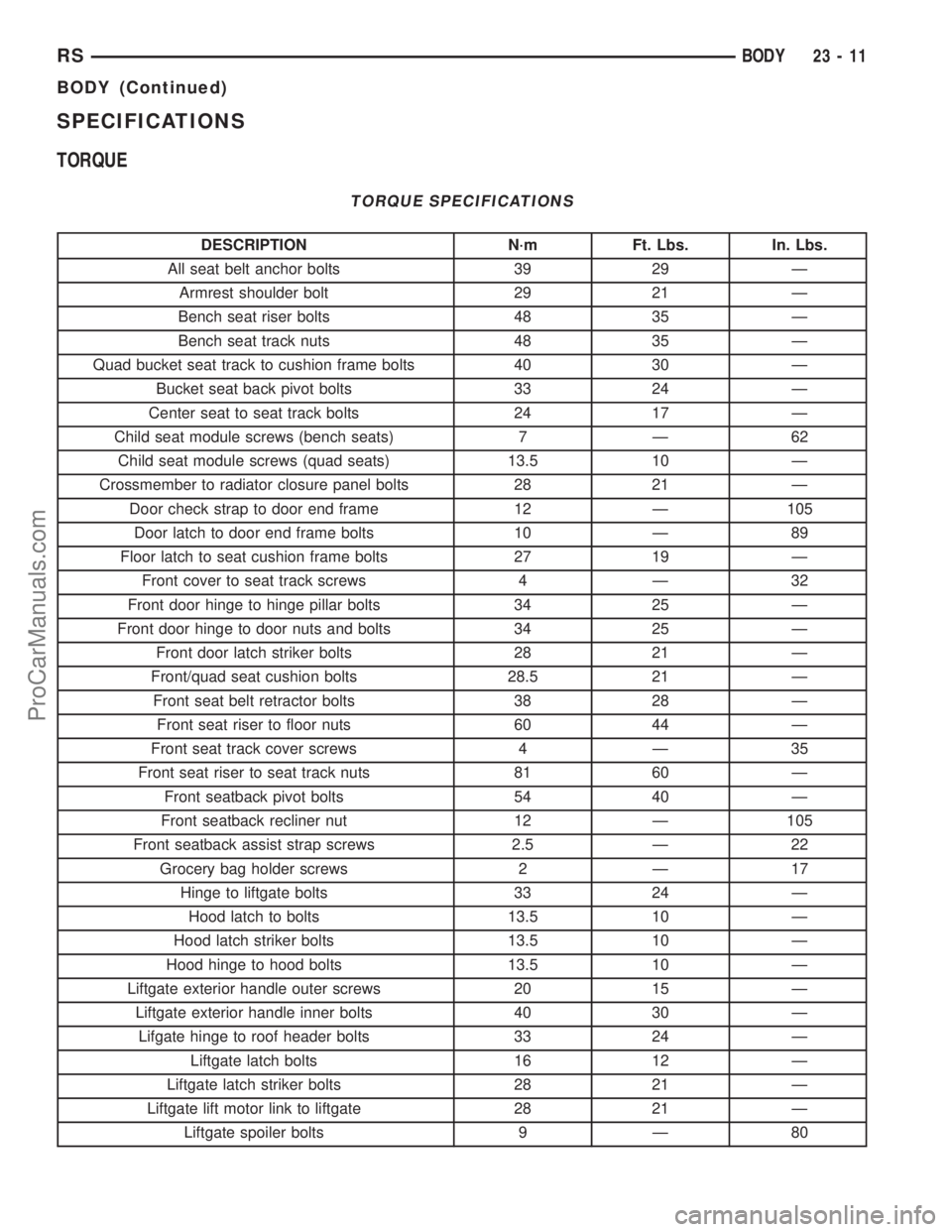
SPECIFICATIONS
TORQUE
TORQUE SPECIFICATIONS
DESCRIPTION N´m Ft. Lbs. In. Lbs.
All seat belt anchor bolts 39 29 Ð
Armrest shoulder bolt 29 21 Ð
Bench seat riser bolts 48 35 Ð
Bench seat track nuts 48 35 Ð
Quad bucket seat track to cushion frame bolts 40 30 Ð
Bucket seat back pivot bolts 33 24 Ð
Center seat to seat track bolts 24 17 Ð
Child seat module screws (bench seats) 7 Ð 62
Child seat module screws (quad seats) 13.5 10 Ð
Crossmember to radiator closure panel bolts 28 21 Ð
Door check strap to door end frame 12 Ð 105
Door latch to door end frame bolts 10 Ð 89
Floor latch to seat cushion frame bolts 27 19 Ð
Front cover to seat track screws 4 Ð 32
Front door hinge to hinge pillar bolts 34 25 Ð
Front door hinge to door nuts and bolts 34 25 Ð
Front door latch striker bolts 28 21 Ð
Front/quad seat cushion bolts 28.5 21 Ð
Front seat belt retractor bolts 38 28 Ð
Front seat riser to floor nuts 60 44 Ð
Front seat track cover screws 4 Ð 35
Front seat riser to seat track nuts 81 60 Ð
Front seatback pivot bolts 54 40 Ð
Front seatback recliner nut 12 Ð 105
Front seatback assist strap screws 2.5 Ð 22
Grocery bag holder screws 2 Ð 17
Hinge to liftgate bolts 33 24 Ð
Hood latch to bolts 13.5 10 Ð
Hood latch striker bolts 13.5 10 Ð
Hood hinge to hood bolts 13.5 10 Ð
Liftgate exterior handle outer screws 20 15 Ð
Liftgate exterior handle inner bolts 40 30 Ð
Lifgate hinge to roof header bolts 33 24 Ð
Liftgate latch bolts 16 12 Ð
Liftgate latch striker bolts 28 21 Ð
Liftgate lift motor link to liftgate 28 21 Ð
Liftgate spoiler bolts 9 Ð 80
RSBODY23-11
BODY (Continued)
ProCarManuals.com
Page 2013 of 2399
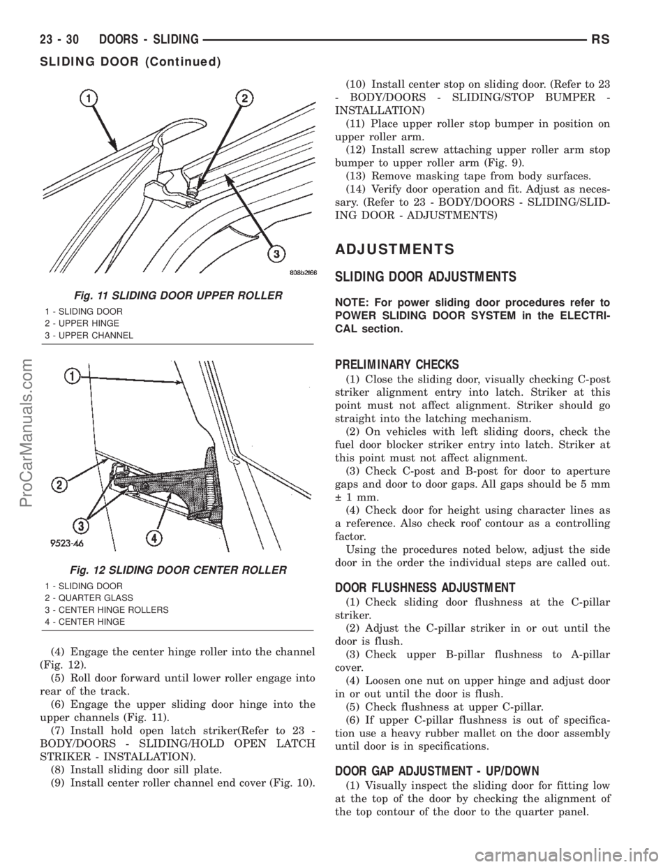
(4) Engage the center hinge roller into the channel
(Fig. 12).
(5) Roll door forward until lower roller engage into
rear of the track.
(6) Engage the upper sliding door hinge into the
upper channels (Fig. 11).
(7) Install hold open latch striker(Refer to 23 -
BODY/DOORS - SLIDING/HOLD OPEN LATCH
STRIKER - INSTALLATION).
(8) Install sliding door sill plate.
(9) Install center roller channel end cover (Fig. 10).(10) Install center stop on sliding door. (Refer to 23
- BODY/DOORS - SLIDING/STOP BUMPER -
INSTALLATION)
(11) Place upper roller stop bumper in position on
upper roller arm.
(12) Install screw attaching upper roller arm stop
bumper to upper roller arm (Fig. 9).
(13) Remove masking tape from body surfaces.
(14) Verify door operation and fit. Adjust as neces-
sary. (Refer to 23 - BODY/DOORS - SLIDING/SLID-
ING DOOR - ADJUSTMENTS)
ADJUSTMENTS
SLIDING DOOR ADJUSTMENTS
NOTE: For power sliding door procedures refer to
POWER SLIDING DOOR SYSTEM in the ELECTRI-
CAL section.
PRELIMINARY CHECKS
(1) Close the sliding door, visually checking C-post
striker alignment entry into latch. Striker at this
point must not affect alignment. Striker should go
straight into the latching mechanism.
(2) On vehicles with left sliding doors, check the
fuel door blocker striker entry into latch. Striker at
this point must not affect alignment.
(3) Check C-post and B-post for door to aperture
gaps and door to door gaps. All gaps should be 5 mm
1 mm.
(4) Check door for height using character lines as
a reference. Also check roof contour as a controlling
factor.
Using the procedures noted below, adjust the side
door in the order the individual steps are called out.
DOOR FLUSHNESS ADJUSTMENT
(1) Check sliding door flushness at the C-pillar
striker.
(2) Adjust the C-pillar striker in or out until the
door is flush.
(3) Check upper B-pillar flushness to A-pillar
cover.
(4) Loosen one nut on upper hinge and adjust door
in or out until the door is flush.
(5) Check flushness at upper C-pillar.
(6) If upper C-pillar flushness is out of specifica-
tion use a heavy rubber mallet on the door assembly
until door is in specifications.
DOOR GAP ADJUSTMENT - UP/DOWN
(1) Visually inspect the sliding door for fitting low
at the top of the door by checking the alignment of
the top contour of the door to the quarter panel.
Fig. 11 SLIDING DOOR UPPER ROLLER
1 - SLIDING DOOR
2 - UPPER HINGE
3 - UPPER CHANNEL
Fig. 12 SLIDING DOOR CENTER ROLLER
1 - SLIDING DOOR
2 - QUARTER GLASS
3 - CENTER HINGE ROLLERS
4 - CENTER HINGE
23 - 30 DOORS - SLIDINGRS
SLIDING DOOR (Continued)
ProCarManuals.com
Page 2019 of 2399

UPPER HINGE
REMOVAL
(1) Open sliding door, do not latch open.
(2) Remove screw attaching upper stop bracket to
upper roller bracket (Fig. 23).
(3) Remove stop bracket from vehicle.
(4) Place a padded block between the open sliding
door and the roof rail.
(5) Mark outline of upper hinge bracket on sliding
door.
(6) Remove bolts attaching upper roller to sliding
door (Fig. 24).
(7) Remove upper hinge from door.
(8) Slide roller out of rear end of roof upper chan-
nel.
(9) Remove upper hinge from vehicle.
INSTALLATION
(1) Place upper hinge in position on vehicle (Fig.
24).
(2) Slide roller into rear end of roof upper channel.
(3) Place upper hinge in position on door.
(4) Align outline marks on sliding door to upper
roller bracket
(5) Install bolts attaching upper hinge to sliding
door.
(6) Remove padded block from between sliding
door and roof rail.
(7) Place stop bracket in position on vehicle.
(8) Install screw attaching upper stop bracket to
upper roller bracket (Fig. 23).
(9) Verify sliding door alignment and operation.
Adjust as necessary. (Refer to 23 - BODY/DOORS -
SLIDING/SLIDING DOOR - ADJUSTMENTS)
OUTSIDE HANDLE CABLE
REMOVAL
NOTE: For power sliding door procedures refer to
POWER SLIDING DOOR SYSTEM in the ELECTRI-
CAL section.
(1) Disconnect and isolate the negative battery
cable.
(2) Remove stop bumper (Refer to 23 - BODY/
DOORS - SLIDING/STOP BUMPER - REMOVAL).
(3) Remove the appropriate side door trim panel.
(Refer to 23 - BODY/DOORS - SLIDING/TRIM
PANEL - REMOVAL)
(4) Peel watershield away from adhesive around
perimeter of inner door panel.
CAUTION: Make note of cable routing and foam
insulator placement. This will prove helpful when
reinstalling replacement cable. Be certain replace-
ment cable is routed and retained correctly.
(5) Trace the outside handle cable along its routing
path and disconnect from its retaining clips.
(6) Disconnect the outside handle cable from the
latch assembly. Gently pry cable sleeve retainer out
of the latch mounting bracket and then unhook
swedged cable end from the latch link.
(7) Disconnect the outside handle cable from the
handle assembly. Gently pry cable sleeve retainer out
of the handle bracket and then unhook swedged
cable end from the handle link.
(8) Remove the outside handle cable from the side
door.
Fig. 23 SLIDING DOOR UPPER STOP
1 - UPPER STOP PLATE
2 - SLIDING DOOR
3 - UPPER SLIDING DOOR HINGE
Fig. 24 SLIDING DOOR UPPER HINGE
1 - SLIDING DOOR UPPER HINGE
2 - SLIDING DOOR
23 - 36 DOORS - SLIDINGRS
ProCarManuals.com
Page 2027 of 2399
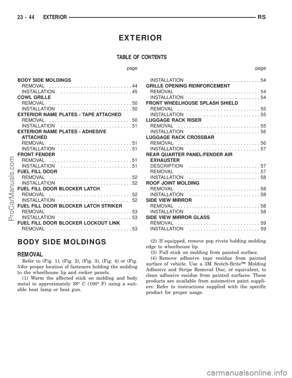
EXTERIOR
TABLE OF CONTENTS
page page
BODY SIDE MOLDINGS
REMOVAL.............................44
INSTALLATION.........................45
COWL GRILLE
REMOVAL.............................50
INSTALLATION.........................50
EXTERIOR NAME PLATES - TAPE ATTACHED
REMOVAL.............................50
INSTALLATION.........................51
EXTERIOR NAME PLATES - ADHESIVE
ATTACHED
REMOVAL.............................51
INSTALLATION.........................51
FRONT FENDER
REMOVAL.............................51
INSTALLATION.........................51
FUEL FILL DOOR
REMOVAL.............................52
INSTALLATION.........................52
FUEL FILL DOOR BLOCKER LATCH
REMOVAL.............................52
INSTALLATION.........................52
FUEL FILL DOOR BLOCKER LATCH STRIKER
REMOVAL.............................53
INSTALLATION.........................53
FUEL FILL DOOR BLOCKER LOCKOUT LINK
REMOVAL.............................53INSTALLATION.........................54
GRILLE OPENING REINFORCEMENT
REMOVAL.............................54
INSTALLATION.........................54
FRONT WHEELHOUSE SPLASH SHIELD
REMOVAL.............................55
INSTALLATION.........................55
LUGGAGE RACK RISER
REMOVAL.............................55
INSTALLATION.........................56
LUGGAGE RACK CROSSBAR
REMOVAL.............................56
INSTALLATION.........................57
REAR QUARTER PANEL/FENDER AIR
EXHAUSTER
DESCRIPTION.........................57
REMOVAL.............................57
INSTALLATION.........................58
ROOF JOINT MOLDING
REMOVAL.............................58
INSTALLATION.........................58
SIDE VIEW MIRROR
REMOVAL.............................58
INSTALLATION.........................58
SIDE VIEW MIRROR GLASS
REMOVAL.............................59
INSTALLATION.........................59
BODY SIDE MOLDINGS
REMOVAL
Refer to (Fig. 1), (Fig. 2), (Fig. 3), (Fig. 4) or (Fig.
5)for proper location of fasteners holding the molding
to the wheelhouse lip and rocker panels.
(1) Warm the affected stick on molding and body
metal to approximately 38É C (100É F) using a suit-
able heat lamp or heat gun.(2) If equipped, remove pop rivets holding molding
edge to wheelhouse lip.
(3) Pull stick on molding from painted surface.
(4) Remove adhesive tape residue from painted
surface of vehicle. Use a 3M Scotch-BriteŸ Molding
Adhesive and Stripe Removal Disc, or equivalent, to
clean adhesive residue from painted surfaces. These
products are available from automotive paint suppli-
ers. Refer to instructions supplied with the specific
product for proper usage.
23 - 44 EXTERIORRS
ProCarManuals.com
Page 2060 of 2399
(12) If equipped, install overhead console.
(13) Install liftgate opening header trim.
(14) Install D-pillar trim covers.
(15) Install C-pillar upper trim covers.
(16) Install B-pillar upper trim covers.
(17) Install A-pillar trim covers.
LEFT D-PILLAR TRIM PANEL
REMOVAL
(1) Remove rear header trim cover.
(2) Remove liftgate sill plate.
(3) Remove second row seat belt turning loop on
long wheel base vehicle.
(4) Remove bolt attaching second row seat belt
lower anchor to quarter on short wheel base vehicle.
(5) Disengage hidden clips attaching trim to D-pil-
lar.
(6) Disconnect speaker wire connector, if equipped.
(7) Pass seat belt through slot in D-pillar trim
panel on short wheel base vehicle.
(8) Remove D-pillar trim from vehicle.
INSTALLATION
(1) Pass seat belt through slot in D-pillar trim
panel on short wheel base vehicle.
(2) Position D-pillar trim panel on vehicle.
(3) Connect speaker wire connector to speaker, if
equipped.
(4) Align locating pins on backside of trim panel to
mating holes in inner quarter panel.(5) Engage hidden clips attaching trim to D-pillar.
(6) Install bolt attaching second row seat belt
lower anchor to quarter on short wheel base vehicle.
Tighten all seat belt bolts to 39 N´m (29 ft. lbs.).
(7) Install second row seat belt turning loop on
long wheel base vehicle.
(8) Install liftgate sill plate.
(9) Install rear header trim cover.
LIFTGATE SILL PLATE
REMOVAL
(1) Disengage hidden clips holding sill plate to lift-
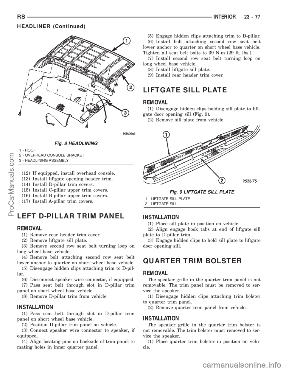
gate door opening sill (Fig. 9).
(2) Remove sill plate from vehicle.
INSTALLATION
(1) Place sill plate in position on vehicle.
(2) Align engage hook tabs at end of liftgate sill
plate to D-pillar trim.
(3) Engage hidden clips to hold sill plate to liftgate
door opening sill.
QUARTER TRIM BOLSTER
REMOVAL
The speaker grille in the quarter trim panel is not
removable. The trim panel must be removed to ser-
vice the speaker.
(1) Disengage hidden clips attaching trim bolster
to quarter trim panel.
(2) Remove quarter trim panel from vehicle.
INSTALLATION
The speaker grille in the quarter trim bolster is
not removable. The trim bolster must removed to ser-
vice the speaker.
(1) Place quarter trim bolster in position on vehi-
cle.
Fig. 8 HEADLINING
1 - ROOF
2 - OVERHEAD CONSOLE BRACKET
3 - HEADLINING ASSEMBLY
Fig. 9 LIFTGATE SILL PLATE
1 - LIFTGATE SILL PLATE
2 - LIFTGATE SILL
RSINTERIOR23-77
HEADLINER (Continued)
ProCarManuals.com
Page 2104 of 2399
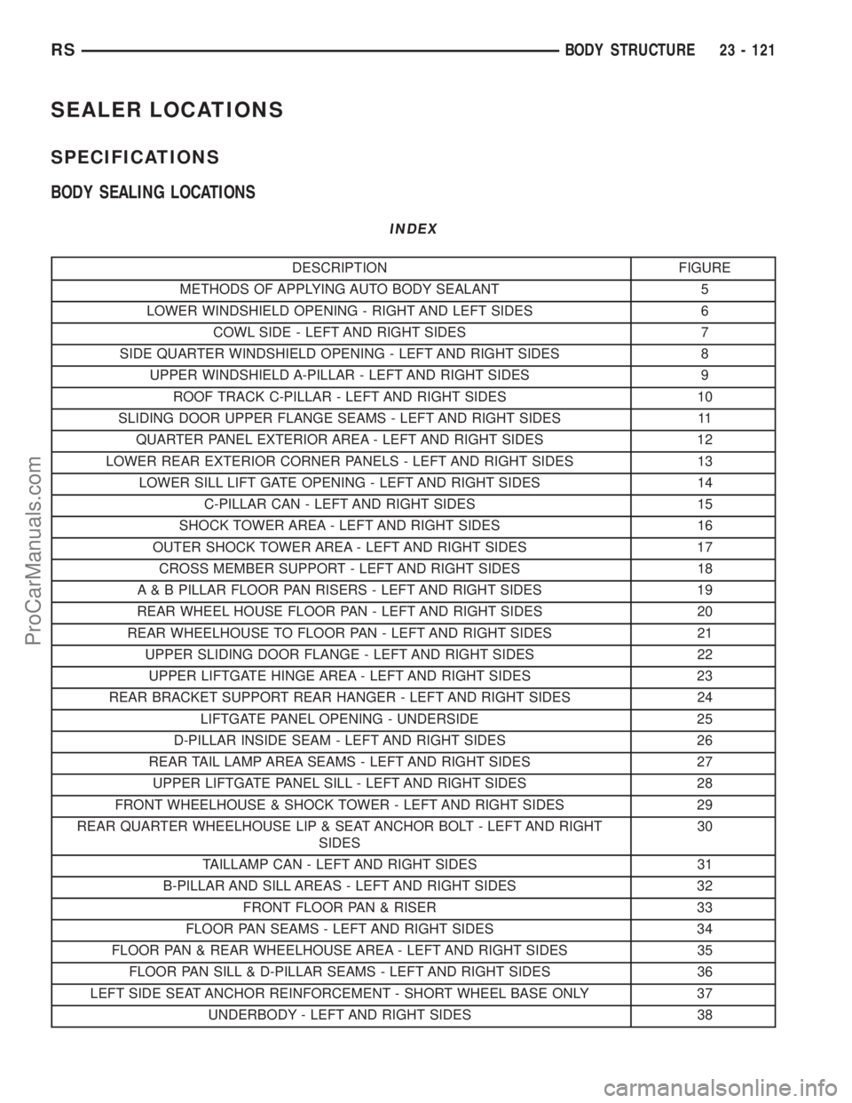
SEALER LOCATIONS
SPECIFICATIONS
BODY SEALING LOCATIONS
INDEX
DESCRIPTION FIGURE
METHODS OF APPLYING AUTO BODY SEALANT 5
LOWER WINDSHIELD OPENING - RIGHT AND LEFT SIDES 6
COWL SIDE - LEFT AND RIGHT SIDES 7
SIDE QUARTER WINDSHIELD OPENING - LEFT AND RIGHT SIDES 8
UPPER WINDSHIELD A-PILLAR - LEFT AND RIGHT SIDES 9
ROOF TRACK C-PILLAR - LEFT AND RIGHT SIDES 10
SLIDING DOOR UPPER FLANGE SEAMS - LEFT AND RIGHT SIDES 11
QUARTER PANEL EXTERIOR AREA - LEFT AND RIGHT SIDES 12
LOWER REAR EXTERIOR CORNER PANELS - LEFT AND RIGHT SIDES 13
LOWER SILL LIFT GATE OPENING - LEFT AND RIGHT SIDES 14
C-PILLAR CAN - LEFT AND RIGHT SIDES 15
SHOCK TOWER AREA - LEFT AND RIGHT SIDES 16
OUTER SHOCK TOWER AREA - LEFT AND RIGHT SIDES 17
CROSS MEMBER SUPPORT - LEFT AND RIGHT SIDES 18
A & B PILLAR FLOOR PAN RISERS - LEFT AND RIGHT SIDES 19
REAR WHEEL HOUSE FLOOR PAN - LEFT AND RIGHT SIDES 20
REAR WHEELHOUSE TO FLOOR PAN - LEFT AND RIGHT SIDES 21
UPPER SLIDING DOOR FLANGE - LEFT AND RIGHT SIDES 22
UPPER LIFTGATE HINGE AREA - LEFT AND RIGHT SIDES 23
REAR BRACKET SUPPORT REAR HANGER - LEFT AND RIGHT SIDES 24
LIFTGATE PANEL OPENING - UNDERSIDE 25
D-PILLAR INSIDE SEAM - LEFT AND RIGHT SIDES 26
REAR TAIL LAMP AREA SEAMS - LEFT AND RIGHT SIDES 27
UPPER LIFTGATE PANEL SILL - LEFT AND RIGHT SIDES 28
FRONT WHEELHOUSE & SHOCK TOWER - LEFT AND RIGHT SIDES 29
REAR QUARTER WHEELHOUSE LIP & SEAT ANCHOR BOLT - LEFT AND RIGHT
SIDES30
TAILLAMP CAN - LEFT AND RIGHT SIDES 31
B-PILLAR AND SILL AREAS - LEFT AND RIGHT SIDES 32
FRONT FLOOR PAN & RISER 33
FLOOR PAN SEAMS - LEFT AND RIGHT SIDES 34
FLOOR PAN & REAR WHEELHOUSE AREA - LEFT AND RIGHT SIDES 35
FLOOR PAN SILL & D-PILLAR SEAMS - LEFT AND RIGHT SIDES 36
LEFT SIDE SEAT ANCHOR REINFORCEMENT - SHORT WHEEL BASE ONLY 37
UNDERBODY - LEFT AND RIGHT SIDES 38
RSBODY STRUCTURE23 - 121
ProCarManuals.com