2002 CHRYSLER CARAVAN fold seats
[x] Cancel search: fold seatsPage 619 of 2399

(10) Install floor anchor bolt. Tighten seat belt
anchor bolts to 39 N´m (29 ft. lbs.) torque.
(11) Slide floor anchor cover over the anchor bolt.
(12) Install shoulder harness height adjuster knob
by pushing knob on the adjuster.
SEAT BELT FIRST ROW
OUTBOARD - LWB FOUR DOOR
REMOVAL
(1) Remove first and second row seats. Refer to
Owner's manual for proper procedures.
(2) Remove shoulder harness height adjuster knob
by pulling it straight away from adjuster.
(3) Slide floor anchor cover from over the anchor
bolt.
(4) Remove floor anchor bolt.
(5) Remove anchor from floor.
(6) Open clam shell cover from over seat belt turn-
ing loop.
(7) Remove bolt attaching turning loop to shoulder
belt height adjuster.
(8) Remove turning loop from C-pillar.
(9) Remove lower quarter trim panel.
(10) Route seat belt webbing and turning loop
through access hole in lower quarter trim panel.
(11) Remove bolt attaching seat belt retractor to
quarter panel.
(12) Lift retractor upward and disengage arrow
head retainer attaching retractor to quarter panel.
(13) Remove seat belt from vehicle.
INSTALLATION
(1) Position seat belt to vehicle.
(2) Install arrow head retainer to quarter panel
and push downward to seat retainer.
(3) Install bolt attaching seat belt retractor to
quarter panel.
(4) Route seat belt webbing and turning loop
through access hole in lower quarter trim panel.
(5) Install lower quarter trim panel.
(6) Position turning loop to C-pillar.
(7) Install bolt attaching turning loop to shoulder
belt height adjuster.
(8) Close clam shell cover from over seat belt turn-
ing loop.
(9) Position anchor to floor.
(10) Install floor anchor bolt.
(11) Slide floor anchor cover over the anchor bolt.
(12) Install shoulder harness height adjuster knob
by pushing it straight onto adjuster.
(13) Install first and second row seats. Refer to
Owner's manual for proper procedures.NOTE: The tightening specification for all seat belt
anchor bolts is 39 N´m (29 ft. lbs.) torque.
SEAT BELT SECOND RIGHT
ROW OUTBOARD - LWB
REMOVAL
(1) Remove second row seat from vehicle. Refer to
Owner's Manual for proper procedures.
(2) Slide lower anchor cover from over the anchor
shoulder-nut.
(3) Remove lower anchor shoulder-nut (Fig. 5).
(4) Remove lower anchor from wheelhouse.
(5) Fold upper turning loop extension cover down-
ward to gain access to anchor bolt.
(6) Remove bolt attaching turning loop to exten-
sion bracket above quarter glass (Fig. 5).
(7) Remove turning loop from extension bracket.
(8) Remove D-pillar trim panel.
(9) Remove quarter trim bolster.
(10) Route seat belt webbing and turning loop
through access hole in quarter trim.
(11) Remove bolt attaching retractor to inner quar-
ter panel (Fig. 5).
(12) Remove screw attaching retractor to inner
quarter panel.
(13) Remove second row seat belt retractor from
vehicle.
INSTALLATION
(1) Position second row seat belt retractor in vehi-
cle.
(2) Install screw attaching retractor to inner quar-
ter panel.
(3) Install bolt attaching retractor to inner quarter
panel. Tightening specifications for all seat belt bolts
is 39 N´m (29 ft. lbs.) torque.
(4) Route seat belt webbing and turning loop
through access hole in quarter trim.
(5) Install quarter trim bolster.
(6) Install D-pillar trim panel.
(7) Position turning loop to extension bracket.
(8) Install bolt attaching turning loop to extension
bracket above quarter glass. Tightening specifications
for all seat belt bolts is 39 N´m (29 ft. lbs.) torque.
(9) Install upper turning loop extension cover.
(10) Position lower anchor to wheelhouse.
(11) Install lower anchor shoulder-nut. Tightening
shoulder nut to 39 N´m (29 ft. lbs.) torque.
(12) Install lower anchor cover over the anchor
shoulder-nut.
8O - 10 RESTRAINTSRS
SEAT BELT FIRST ROW OUTBOARD - SWB FOUR DOOR (Continued)
ProCarManuals.com
Page 1301 of 2399
INSTALLATION
(1) Install air box into vehicle and onto the locat-
ing pin.
(2) Install bolt to hold air box to the upper radia-
tor cross member.
(3) Install the inlet hose to the throttle body.
(4) Connect the inlet air temperature sensor (Fig.
16).
(5) Connect the negative battery cable.
CYLINDER HEAD
DESCRIPTION
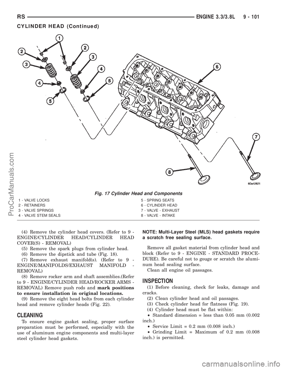
The aluminum cylinder heads (Fig. 17) are
designed to create high flow combustion chambers to
improve performance, while minimizing the change
to the burn rate in the chamber. The cylinder head
incorporates the combustion chamber. Two valves
per-cylinder are used with inserted valve seats and
guides. A multi-layer steel (MLS) type gasket is used
between the cylinder head and engine block.
OPERATION
The cylinder head closes the combustion chamber,
allowing the pistons to compress the fuel/air mixture
for ignition. The valves are actuated by the lobe pro-
files on the camshaft to open and close at specified
duration to either allow clean air in the combustion
chamber or the exhaust gases out; depending on the
stroke of the engine.
DIAGNOSIS AND TESTINGÐCYLINDER HEAD
GASKET
A cylinder head gasket leak can be located between
adjacent cylinders or between a cylinder and the
adjacent water jacket.
Possible indications of the cylinder head gasket
leaking between adjacent cylinders are:
²Loss of engine power
²Engine misfiring
²Poor fuel economy
Possible indications of the cylinder head gasket
leaking between a cylinder and an adjacent water
jacket are:
²Engine overheating
²Loss of coolant
²Excessive steam (white smoke) emitting from
exhaust
²Coolant foaming
CYLINDER-TO-CYLINDER LEAKAGE TEST
To determine if an engine cylinder head gasket is
leaking between adjacent cylinders, follow the proce-
dures in Cylinder Compression Pressure Test (Refer
to 9 - ENGINE - DIAGNOSIS AND TESTING). An
engine cylinder head gasket leaking between adja-
cent cylinders will result in approximately a 50±70%
reduction in compression pressure.
CYLINDER-TO-WATER JACKET LEAKAGE TEST
WARNING: USE EXTREME CAUTION WHEN THE
ENGINE IS OPERATING WITH COOLANT PRES-
SURE CAP REMOVED.
VISUAL TEST METHOD
With the engine cool, remove the coolant pressure
cap. Start the engine and allow it to warm up until
thermostat opens.
If a large combustion/compression pressure leak
exists, bubbles will be visible in the coolant.
COOLING SYSTEM TESTER METHOD
WARNING: WITH COOLING SYSTEM TESTER IN
PLACE, PRESSURE WILL BUILD UP FAST. EXCES-
SIVE PRESSURE BUILT UP, BY CONTINUOUS
ENGINE OPERATION, MUST BE RELEASED TO A
SAFE PRESSURE POINT. NEVER PERMIT PRES-
SURE TO EXCEED 138 kPa (20 psi).
Install Cooling System Tester 7700 or equivalent to
pressure cap neck. Start the engine and observe the
tester's pressure gauge. If gauge pulsates with every
power stroke of a cylinder a combustion pressure
leak is evident.
CHEMICAL TEST METHOD
Combustion leaks into the cooling system can also
be checked by using Bloc-Chek Kit C-3685-A or
equivalent. Perform test following the procedures
supplied with the tool kit.
REMOVAL - CYLINDER HEAD
(1) Drain the cooling system. (Refer to 7 - COOL-
ING - STANDARD PROCEDURE)
(2) Disconnect negative cable from battery.
(3) Remove upper and lower intake manifolds.
(Refer to 9 - ENGINE/MANIFOLDS/INTAKE MANI-
FOLD - REMOVAL)
WARNING: INTAKE MANIFOLD GASKET IS MADE
OF VERY THIN METAL AND MAY CAUSE PER-
SONAL INJURY, HANDLE WITH CARE.
9 - 100 ENGINE 3.3/3.8LRS
AIR CLEANER HOUSING (Continued)
ProCarManuals.com
Page 1302 of 2399
(4) Remove the cylinder head covers. (Refer to 9 -
ENGINE/CYLINDER HEAD/CYLINDER HEAD
COVER(S) - REMOVAL)
(5) Remove the spark plugs from cylinder head.
(6) Remove the dipstick and tube (Fig. 18).
(7) Remove exhaust manifold(s). (Refer to 9 -
ENGINE/MANIFOLDS/EXHAUST MANIFOLD -
REMOVAL)
(8) Remove rocker arm and shaft assemblies.(Refer
to 9 - ENGINE/CYLINDER HEAD/ROCKER ARMS -
REMOVAL) Remove push rods andmark positions
to ensure installation in original locations.
(9) Remove the eight head bolts from each cylinder
head and remove cylinder heads (Fig. 22).
CLEANING
To ensure engine gasket sealing, proper surface
preparation must be performed, especially with the
use of aluminum engine components and multi-layer
steel cylinder head gaskets.NOTE: Multi-Layer Steel (MLS) head gaskets require
a scratch free sealing surface.
Remove all gasket material from cylinder head and
block (Refer to 9 - ENGINE - STANDARD PROCE-
DURE). Be careful not to gouge or scratch the alumi-
num head sealing surface.
Clean all engine oil passages.
INSPECTION
(1) Before cleaning, check for leaks, damage and
cracks.
(2) Clean cylinder head and oil passages.
(3) Check cylinder head for flatness (Fig. 19).
(4) Cylinder head must be flat within:
²Standard dimension = less than 0.05 mm (0.002
inch.)
²Service Limit = 0.2 mm (0.008 inch.)
²Grinding Limit = Maximum of 0.2 mm (0.008
inch.) is permitted.
Fig. 17 Cylinder Head and Components
1 - VALVE LOCKS 5 - SPRING SEATS
2 - RETAINERS 6 - CYLINDER HEAD
3 - VALVE SPRINGS 7 - VALVE - EXHAUST
4 - VALVE STEM SEALS 8 - VALVE - INTAKE
RSENGINE 3.3/3.8L9 - 101
CYLINDER HEAD (Continued)
ProCarManuals.com
Page 2058 of 2399
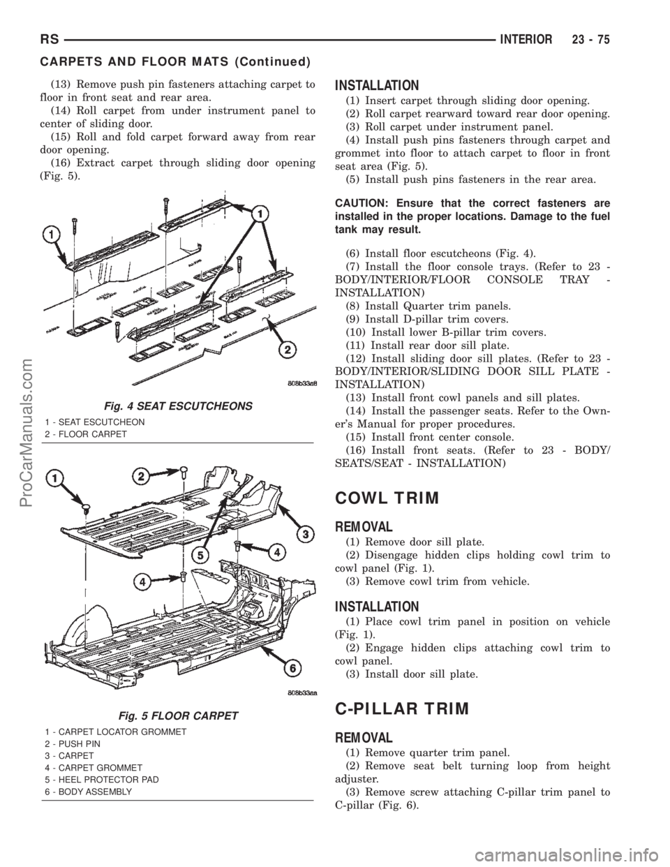
(13) Remove push pin fasteners attaching carpet to
floor in front seat and rear area.
(14) Roll carpet from under instrument panel to
center of sliding door.
(15) Roll and fold carpet forward away from rear
door opening.
(16) Extract carpet through sliding door opening
(Fig. 5).INSTALLATION
(1) Insert carpet through sliding door opening.
(2) Roll carpet rearward toward rear door opening.
(3) Roll carpet under instrument panel.
(4) Install push pins fasteners through carpet and
grommet into floor to attach carpet to floor in front
seat area (Fig. 5).
(5) Install push pins fasteners in the rear area.
CAUTION: Ensure that the correct fasteners are
installed in the proper locations. Damage to the fuel
tank may result.
(6) Install floor escutcheons (Fig. 4).
(7) Install the floor console trays. (Refer to 23 -
BODY/INTERIOR/FLOOR CONSOLE TRAY -
INSTALLATION)
(8) Install Quarter trim panels.
(9) Install D-pillar trim covers.
(10) Install lower B-pillar trim covers.
(11) Install rear door sill plate.
(12) Install sliding door sill plates. (Refer to 23 -
BODY/INTERIOR/SLIDING DOOR SILL PLATE -
INSTALLATION)
(13) Install front cowl panels and sill plates.
(14) Install the passenger seats. Refer to the Own-
er's Manual for proper procedures.
(15) Install front center console.
(16) Install front seats. (Refer to 23 - BODY/
SEATS/SEAT - INSTALLATION)
COWL TRIM
REMOVAL
(1) Remove door sill plate.
(2) Disengage hidden clips holding cowl trim to
cowl panel (Fig. 1).
(3) Remove cowl trim from vehicle.
INSTALLATION
(1) Place cowl trim panel in position on vehicle
(Fig. 1).
(2) Engage hidden clips attaching cowl trim to
cowl panel.
(3) Install door sill plate.
C-PILLAR TRIM
REMOVAL
(1) Remove quarter trim panel.
(2) Remove seat belt turning loop from height
adjuster.
(3) Remove screw attaching C-pillar trim panel to
C-pillar (Fig. 6).
Fig. 4 SEAT ESCUTCHEONS
1 - SEAT ESCUTCHEON
2 - FLOOR CARPET
Fig. 5 FLOOR CARPET
1 - CARPET LOCATOR GROMMET
2 - PUSH PIN
3 - CARPET
4 - CARPET GROMMET
5 - HEEL PROTECTOR PAD
6 - BODY ASSEMBLY
RSINTERIOR23-75
CARPETS AND FLOOR MATS (Continued)
ProCarManuals.com
Page 2070 of 2399

INSTALLATION
INSTALLATION
(1) Place child restraint seat module in position on
seat back (Fig. 4).
(2) Position seat back hinge interlock lever over
the top of the outboard child restraint seat hinge
(Fig. 5).
(3) Install screws attaching child restraint seat
module hinges to seat back frame lower rail (Fig. 1).
(4) Install screws attaching top of module to seat
back frame upper rail (Fig. 3). Tighten nuts to 7 N´m
(62 in. lbs.) torque.(5) Install push in fasteners attaching upper bol-
ster to child restraint seat module (Fig. 2).
(6) Return seat back to folded position.
(7) Install seat back cover.
(8) Verify child restraint seat operation.
SYNCHRONIZING CABLE ADJUSTMENT
NOTE:
Bench seats equipped with child restraint seats
have an interlock feature that will not allow the seat
back to fold forward with the child seat open.
If the seat back hinges do not release at the same
time the synchronizing cable must be adjusted.
(1) Remove seat from vehicle. Refer to Owner's
Manual for proper procedures.
(2) Disengage cable from the recline mechanism by
pulling the cable end toward the front of the seat
(Fig. 6).
(3) Pull U-shaped locking tab on self-adjusting
mehcanism to disengage auto-adjust feature.
(4) Reattach self-adjusting mechanism, pulling
against spring load to tighten cable.
(5) Press locking tab onto the adjusting mecha-
nism to lock into place.
Fig. 4 CHILD RESTRAINT SEAT MODULE
1 - 1ST REAR SEAT BACK
2 - CHILD RESTRAINT SEAT MODULE
3 - SEAT BACK HINGE INTERLOCK LEVER
Fig. 5 INTERLOCK LEVER
1 - CHILD RESTRAINT SEAT HINGE
2 - SEAT BACK HINGE INTERLOCK LEVER
3 - 1ST REAR SEAT BACK
4 - SEAT BACK FRAME RAIL
RSSEATS23-87
CHILD SEAT MODULE (Continued)
ProCarManuals.com
Page 2081 of 2399
(3) Install the seat side shield/cup holder. (Refer to
23 - BODY/SEATS/QUAD BUCKET SEAT SIDE
SHIELD/CUP HOLDER - INSTALLATION)
(4) Install the seat. Refer to Owner's Manual for
proper procedures.
BUCKET SEAT BACK - QUAD
BUCKET
REMOVAL
NOTE: Quad seats equipped with child restraint
seats have an interlock feature that will not allow
the seat back to fold forward with the child seat
open.
(1) Remove the headrests. (Refer to 23 - BODY/
SEATS/HEADREST - REMOVAL)
(2) Remove the armrests, if equipped. (Refer to 23
- BODY/SEATS/ARMREST - REMOVAL)
(3) Remove the seatback hinge covers. (Refer to 23
- BODY/SEATS/SEAT BACK HINGE COVERS -
QUAD BUCKET, 50/50 SPLIT, BENCH - REMOVAL)
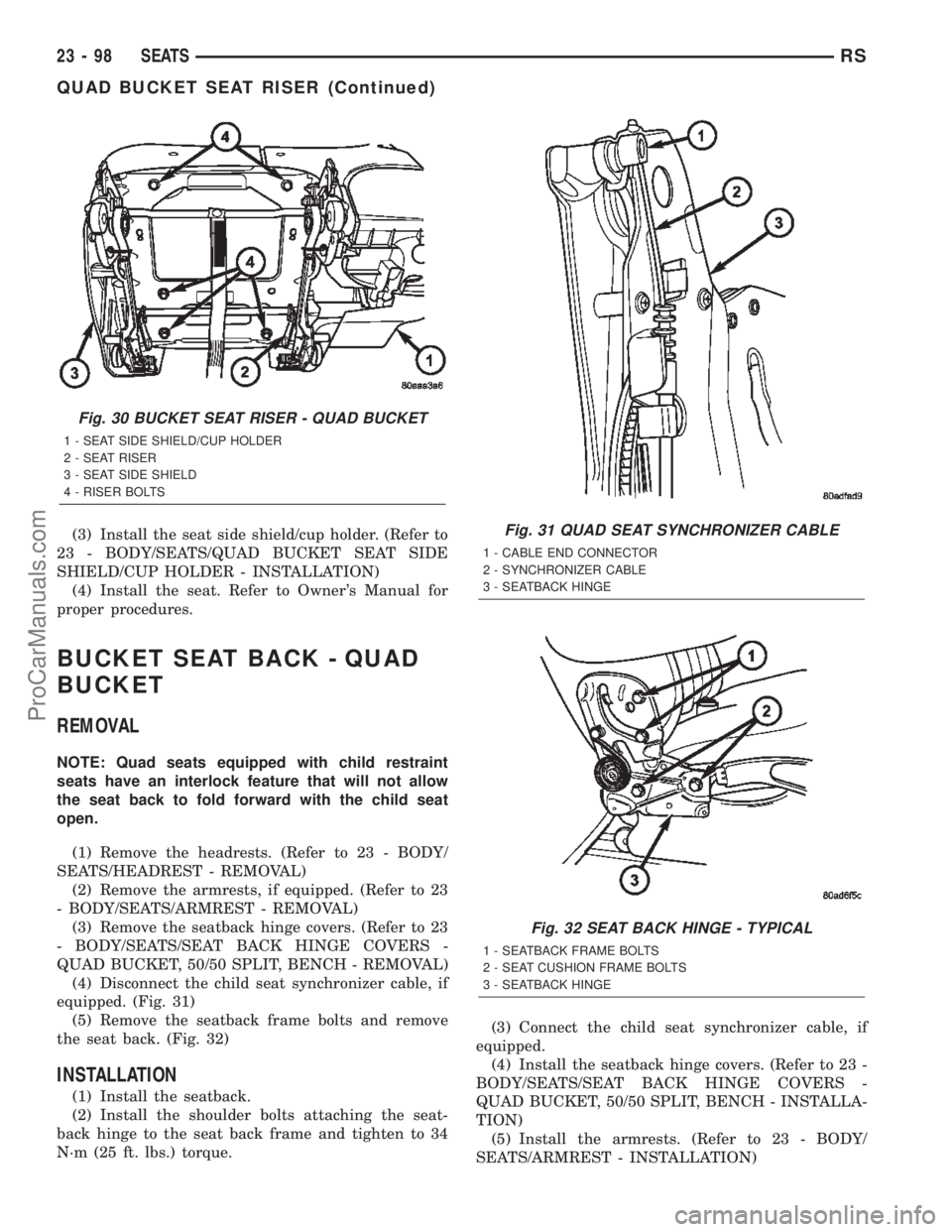
(4) Disconnect the child seat synchronizer cable, if
equipped. (Fig. 31)
(5) Remove the seatback frame bolts and remove
the seat back. (Fig. 32)
INSTALLATION
(1) Install the seatback.
(2) Install the shoulder bolts attaching the seat-
back hinge to the seat back frame and tighten to 34
N´m (25 ft. lbs.) torque.(3) Connect the child seat synchronizer cable, if
equipped.
(4) Install the seatback hinge covers. (Refer to 23 -
BODY/SEATS/SEAT BACK HINGE COVERS -
QUAD BUCKET, 50/50 SPLIT, BENCH - INSTALLA-
TION)
(5) Install the armrests. (Refer to 23 - BODY/
SEATS/ARMREST - INSTALLATION)
Fig. 30 BUCKET SEAT RISER - QUAD BUCKET
1 - SEAT SIDE SHIELD/CUP HOLDER
2 - SEAT RISER
3 - SEAT SIDE SHIELD
4 - RISER BOLTS
Fig. 31 QUAD SEAT SYNCHRONIZER CABLE
1 - CABLE END CONNECTOR
2 - SYNCHRONIZER CABLE
3 - SEATBACK HINGE
Fig. 32 SEAT BACK HINGE - TYPICAL
1 - SEATBACK FRAME BOLTS
2 - SEAT CUSHION FRAME BOLTS
3 - SEATBACK HINGE
23 - 98 SEATSRS
QUAD BUCKET SEAT RISER (Continued)
ProCarManuals.com
Page 2084 of 2399
INSTALLATION
(1) Place riser in position on seat.
(2) Install bolts attaching seat riser to seat cush-
ion frame (Fig. 36). Tighten bolts to 48 N´m (35 ft.
lbs.) torque.
(3) Install seat into vehicle.
BENCH SEAT RISER - THIRD
ROW
REMOVAL
(1) Remove seat track. (Refer to 23 - BODY/
SEATS/BENCH SEAT TRACK - REMOVAL)
(2) Remove bolts attaching riser to seat cushion
frame and remove the riser. (Fig. 41).
INSTALLATION
(1) Place riser in position on seat.
(2) Install bolts attaching riser to seat cushion
frame (Fig. 41). Tighten nuts to 48 N´m (35 ft. lbs.)
torque.
(3) Install seat track. (Refer to 23 - BODY/SEATS/
BENCH SEAT TRACK - INSTALLATION)
SEAT BACK HINGE COVERS -
QUAD BUCKET, 50/50 SPLIT,
BENCH
REMOVAL
(1) Remove seat from vehicle. Refer to Owner's
Manual for proper procedures.
(2) Remove screws attaching upper hinge cover to
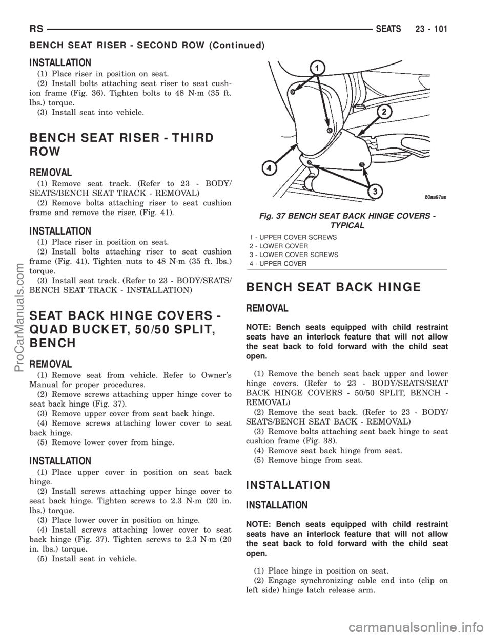
seat back hinge (Fig. 37).
(3) Remove upper cover from seat back hinge.
(4) Remove screws attaching lower cover to seat
back hinge.
(5) Remove lower cover from hinge.
INSTALLATION
(1) Place upper cover in position on seat back
hinge.
(2) Install screws attaching upper hinge cover to
seat back hinge. Tighten screws to 2.3 N´m (20 in.
lbs.) torque.
(3) Place lower cover in position on hinge.
(4) Install screws attaching lower cover to seat
back hinge (Fig. 37). Tighten screws to 2.3 N´m (20
in. lbs.) torque.
(5) Install seat in vehicle.
BENCH SEAT BACK HINGE
REMOVAL
NOTE: Bench seats equipped with child restraint
seats have an interlock feature that will not allow
the seat back to fold forward with the child seat
open.
(1) Remove the bench seat back upper and lower
hinge covers. (Refer to 23 - BODY/SEATS/SEAT
BACK HINGE COVERS - 50/50 SPLIT, BENCH -
REMOVAL)
(2) Remove the seat back. (Refer to 23 - BODY/
SEATS/BENCH SEAT BACK - REMOVAL)
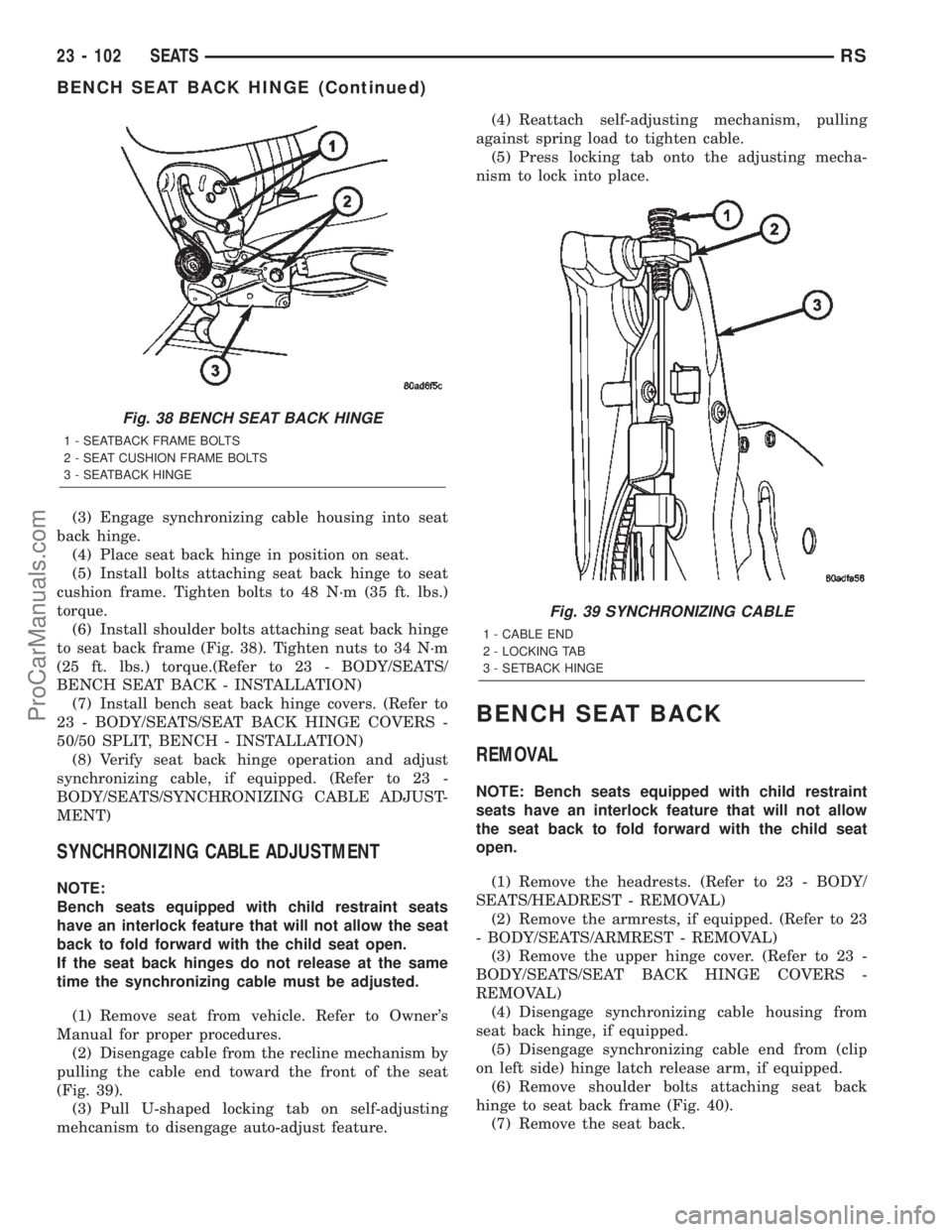
(3) Remove bolts attaching seat back hinge to seat
cushion frame (Fig. 38).
(4) Remove seat back hinge from seat.
(5) Remove hinge from seat.
INSTALLATION
INSTALLATION
NOTE: Bench seats equipped with child restraint
seats have an interlock feature that will not allow
the seat back to fold forward with the child seat
open.
(1) Place hinge in position on seat.
(2) Engage synchronizing cable end into (clip on
left side) hinge latch release arm.
Fig. 37 BENCH SEAT BACK HINGE COVERS -
TYPICAL
1 - UPPER COVER SCREWS
2 - LOWER COVER
3 - LOWER COVER SCREWS
4 - UPPER COVER
RSSEATS23 - 101
BENCH SEAT RISER - SECOND ROW (Continued)
ProCarManuals.com
Page 2085 of 2399
(3) Engage synchronizing cable housing into seat
back hinge.
(4) Place seat back hinge in position on seat.
(5) Install bolts attaching seat back hinge to seat
cushion frame. Tighten bolts to 48 N´m (35 ft. lbs.)
torque.
(6) Install shoulder bolts attaching seat back hinge
to seat back frame (Fig. 38). Tighten nuts to 34 N´m
(25 ft. lbs.) torque.(Refer to 23 - BODY/SEATS/
BENCH SEAT BACK - INSTALLATION)
(7) Install bench seat back hinge covers. (Refer to
23 - BODY/SEATS/SEAT BACK HINGE COVERS -
50/50 SPLIT, BENCH - INSTALLATION)
(8) Verify seat back hinge operation and adjust
synchronizing cable, if equipped. (Refer to 23 -
BODY/SEATS/SYNCHRONIZING CABLE ADJUST-
MENT)
SYNCHRONIZING CABLE ADJUSTMENT
NOTE:
Bench seats equipped with child restraint seats
have an interlock feature that will not allow the seat
back to fold forward with the child seat open.
If the seat back hinges do not release at the same
time the synchronizing cable must be adjusted.
(1) Remove seat from vehicle. Refer to Owner's
Manual for proper procedures.
(2) Disengage cable from the recline mechanism by
pulling the cable end toward the front of the seat
(Fig. 39).
(3) Pull U-shaped locking tab on self-adjusting
mehcanism to disengage auto-adjust feature.(4) Reattach self-adjusting mechanism, pulling
against spring load to tighten cable.
(5) Press locking tab onto the adjusting mecha-
nism to lock into place.
BENCH SEAT BACK
REMOVAL
NOTE: Bench seats equipped with child restraint
seats have an interlock feature that will not allow
the seat back to fold forward with the child seat
open.
(1) Remove the headrests. (Refer to 23 - BODY/
SEATS/HEADREST - REMOVAL)
(2) Remove the armrests, if equipped. (Refer to 23
- BODY/SEATS/ARMREST - REMOVAL)
(3) Remove the upper hinge cover. (Refer to 23 -
BODY/SEATS/SEAT BACK HINGE COVERS -
REMOVAL)
(4) Disengage synchronizing cable housing from
seat back hinge, if equipped.
(5) Disengage synchronizing cable end from (clip
on left side) hinge latch release arm, if equipped.
(6) Remove shoulder bolts attaching seat back
hinge to seat back frame (Fig. 40).
(7) Remove the seat back.
Fig. 38 BENCH SEAT BACK HINGE
1 - SEATBACK FRAME BOLTS
2 - SEAT CUSHION FRAME BOLTS
3 - SEATBACK HINGE
Fig. 39 SYNCHRONIZING CABLE
1 - CABLE END
2 - LOCKING TAB
3 - SETBACK HINGE
23 - 102 SEATSRS
BENCH SEAT BACK HINGE (Continued)
ProCarManuals.com