Page 58 of 399

2-
2-1
Section 2 Features and Controls
Here you can learn about the many standard and optional features on your vehicle, and information on starting,
shifting and braking. Also explained are the instrument panel and the warning systems that tell you if everything is
working properly
-- and what to do if you have a problem.
2
-2 Windows
2
-5 Keys
2
-7 Door Locks
2
-10 Remote Keyless Entry System
2
-14 Trunk
2
-17 Theft
2
-18 Theft-Deterrent System
2
-20 PASS-Key� III
2
-22 New Vehicle ªBreak-Inº
2
-22 Ignition Positions
2
-24 Starting Your Engine
2
-25 Engine Coolant Heater (If Equipped)
2
-27 Automatic Transaxle Operation
2
-31 Parking Brake
2
-33 Shifting Into PARK (P)
2
-35 Shifting Out of PARK (P)
2
-35 Parking Over Things That Burn
2
-36 Engine Exhaust2
-36 Running Your Engine While You're Parked
2
-37 Tilt Wheel
2
-39 Turn Signal/Multifunction Lever
2
-46 Exterior Lamps
2
-51 Interior Lamps
2
-53 Mirrors
2
-58 Storage Compartments
2
-59 Sun Visors
2
-66 Sunroof (Option)
2
-67 HomeLink� Transmitter (If Equipped)
2
-70 The Instrument Panel -- Your
Information System
2
-75 Warning Lights, Gages and Indicators
2
-88 Driver Information Center (DIC)
2
-99 Vehicle Programming and
Personalization Features
2
-113 Navigation (Option)
2
-114 Ultrasonic Rear Parking Assist (URPA)
Page 80 of 399

2-23
OFF: This is the only position in which you can insert
or remove the key. This position also locks the transaxle.
It's a theft
-deterrent feature.
ACC (Accessory): This position lets you use things
like the radio, windshield wipers, power windows and
sunroof (option) when the engine is off. Use ACC if you
must have your vehicle in motion while the engine is off
(for example, if your vehicle is being pushed or towed).
ON: This is the position for driving.
START: This position starts the engine.
Retained Accessory Power (RAP)
The following accessories on your vehicle may be used
for up to 10 minutes after the ignition key is turned
from ON to OFF:
�Cellular Phone (If Equipped)
�Radio
�Power Windows
�Audio Steering Wheel Controls
�Sunroof (Option)
Power to these accessories stops after 10 minutes or
if a door is opened. If you want power for another
10 minutes, close all the doors and turn the ignition key
to ON and then back to OFF. If the cellular phone is
being used while retained accessory power is active,
the timer is suspended to avoid interruption of the call.
The timer resets to 10 minutes at the end of the call.
Page 123 of 399

2-66
Sunroof (Option)
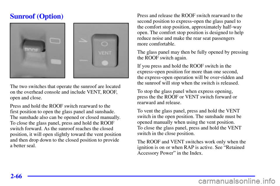
The two switches that operate the sunroof are located
on the overhead console and include VENT, ROOF,
open and close.
Press and hold the ROOF switch rearward to the
first position to open the glass panel and sunshade.
The sunshade also can be opened or closed manually.
To close the glass panel, press and hold the ROOF
switch forward. As the sunroof reaches the closed
position, it will open slightly toward the vent position
and then drop down to the closed position to provide
a better seal.Press and release the ROOF switch rearward to the
second position to express
-open the glass panel to
the comfort stop position, approximately half
-way
open. The comfort stop position is designed to help
reduce noise and make the rear seat passengers
more comfortable.
The glass panel may then be fully opened by pressing
the ROOF switch again.
If you press and hold the ROOF switch in the
express
-open position for more than one second,
the express
-open operation will be over-ridden and
the sunroof will stop when the switch is released.
To stop the glass panel when express opening,
press the the ROOF or VENT switch forward or
rearward and release.
To vent the glass panel, press and hold the VENT
switch in the open position. The sunshade must be
opened manually when using the vent position.
To close the glass panel, press and hold the VENT
switch in the close position.
The ROOF and VENT switches work only when the
ignition is on or when RAP is active. See ªRetained
Accessory Powerº in the Index.
Page 208 of 399

3-36 Diversity Antenna System
Your AM-FM antennas are located in the front
windshield and rear window. Be sure that the inside
surfaces of the front windshield and rear window are not
scratched and that the lines on the glass are not
damaged. If the inside surfaces are damaged, they could
interfere with radio reception. Also, for proper radio
reception, the antenna connector located on the
passengers side top corner of the front windshield and
the antenna connector located on the drivers side top
corner of the rear window need to be properly attached
to the buttons on the glass.
Do not apply aftermarket glass tinting. The metallic film
in some tinting materials will interfere with or distort the
incoming radio reception.
NOTICE:
Do not try to clear frost or other material from
the inside of the front windshield or rear window
with a razor blade or anything else that is sharp.
This may damage the grid lines and affect your
radio's ability to pick up stations clearly. The
repairs wouldn't be covered by your warranty.
If, when you turn on your rear window defogger, you
hear static on your radio station, it could mean that a
defogger grid line has been damaged. If this is true,
the grid line must be repaired.
If you choose to add an aftermarket cellular telephone to
your vehicle, and the antenna needs to be attached to the
glass, be sure that you do not damage the grid lines for
the AM
-FM antennas or place the cellular telephone
antenna over the grid lines.
XM Satellite Radio Antenna System
(If Equipped)
Your XM Satellite Radio antenna is located on the roof
of your vehicle. Keep this antenna clear of snow and ice
build up for clear radio reception.
Page 358 of 399
6-77
Minifuses Usage
14 Interior Lamp Dimmer Module
15 Navigation
16 Heated Seat Left Front
17 Export Lighting
18 Rear Door Modules
19 Stoplamps
20 Neutral Safety Back
-up
21 Audio
22 Retained Accessory Power
for Sunroof
23 Not Used
24 Not Used
25 Passenger Door Module
26 Fuel Door/Trunk Release (Body)
27 Interior Lamps
28 Rear HVAC BlowerMinifuses Usage
29 Ignition Switch
30 Not Used
31 Heated Seat Right Front
32 Continuous Variable Road
Sensing Suspension
33 Heating, Ventilation,
Air Conditioning
34 Ignition 3 Rear
35 Antilock Braking System
36 Turn Signal/Hazard
37 Heated Seat Right Rear
38 Dash Integration Module
Micro Relays Usage
39 Fuel Pump
40 Parking Lamps
41 Ignition 1
Page 359 of 399
6-78
Micro Relays Usage
42 Park Brake A
43 Park Brake B
44 Park Shift Interlock
45 Reverse Lamps
46 Retained Accessory Power
for Sunroof
47 Rear HVAC Blower
48 Suspension Dampers
49 Ignition 3
50 Fuel Tank Door Release
51 Interior Lamps
52 Trunk Release
53 Front Courtesy Lamps
54 Rear Courtesy Lamps
55 Electronic Level
Control CompressorMini Breakers Usage
56 Power Seats
57 Power Windows
Mini Relays Usage
58 Cigarette Lighter
59 Rear Defog
MaxiFuses Usage
60 Park Brake
61 Rear Defog
62 Export Brake
63 Audio Amplifier
64 ELC Compressor/Exhaust
65 Cigar Lighter
66 Not Used
The spare fuses are located in numbers 69 through 74.
The fuse puller is located in number 75.