Page 16 of 80

Workshop Hints
Windshield Wiper Blade Service
To access the wiper blades for cleaning or replacement,the following is required:
• With the ignition switched on (KL15), switch the wiper stalk to the “Intermittant” wipe
mode.
• Switch the ignition off when the wiper arms are in the “upright” position.
CAUTION: Do not allow the wiper arm to spring back against the windshield, glass
breakage will occur!
Rain Sensor Equipped Vehicles
Make sure the wiper blades are in perfect condition. Only use window cleaner to clean the
windows. Dirty windows can cause the Rain Sensor control module to set a fault
due to the end limits of its adaptation abilities.
Rear Window/Wiper
The wiper arm and driveshaft are connected by
splines.
Special tool #61 1 320 is required to hold the drive
shaft in the park position prior to installing the wiper
arm on to the drive shaft.
Windshield Wiper System Diagnosis
The GM monitors the following circuits:
• Wiper Potentiometer • Wiper Motor • Terminal 30
• Double Relay • Windshield Washer Pump
Note: The wiper/washer operation will be interrupted during engine cranking. The GM pro-
vides this “unload” feature to preserve the battery voltage for the starter motor.
16
Central Body Electronics ZKE III
12510117.jpg
Page 69 of 80

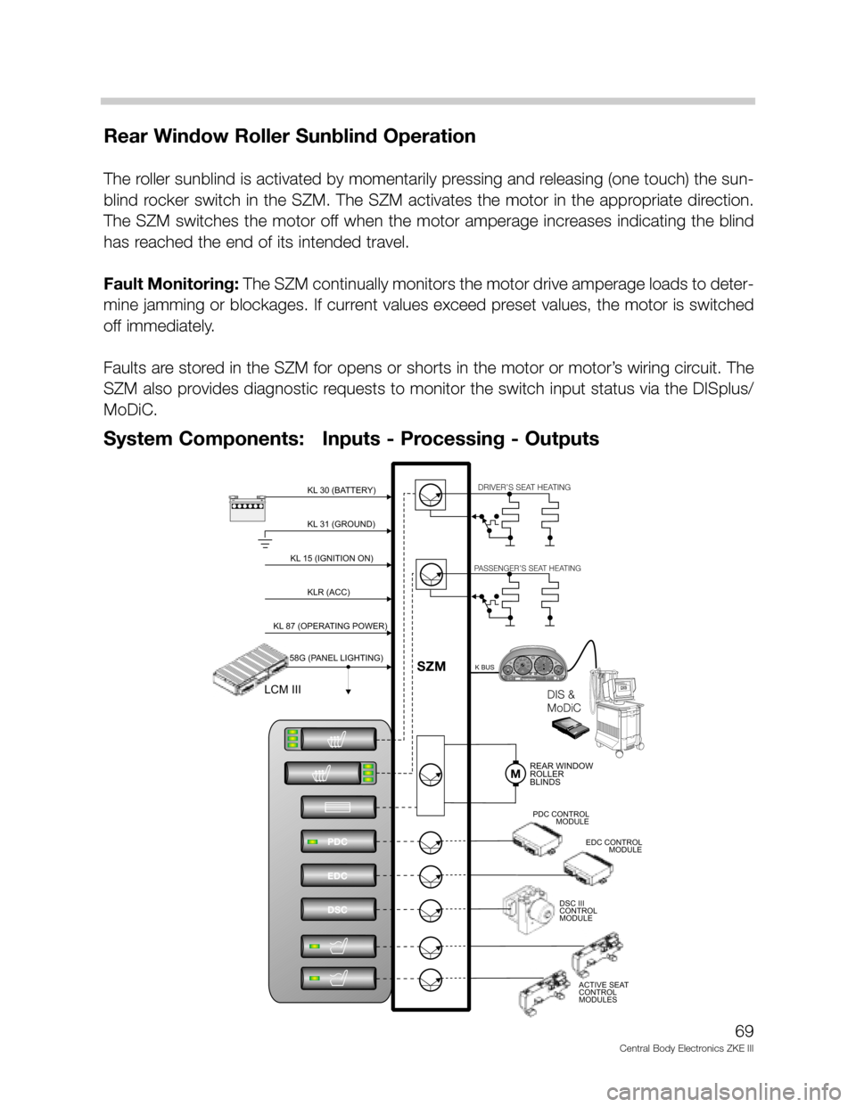
Rear Window Roller Sunblind Operation
The roller sunblind is activated by momentarily pressing and releasing (one touch) the sun-
blind rocker switch in the SZM. The SZM activates the motor in the appropriate direction.
The SZM switches the motor off when the motor amperage increases indicating the blind
has reached the end of its intended travel.
Fault Monitoring: The SZM continually monitors the motor drive amperage loads to deter-
mine jamming or blockages. If current values exceed preset values, the motor is switched
off immediately.
Faults are stored in the SZM for opens or shorts in the motor or motor’s wiring circuit. The
SZM also provides diagnostic requests to monitor the switch input status via the DISplus/
MoDiC.
69
Central Body Electronics ZKE III
KL 31 (GROUND)KL 31 (GROUND)
DIS
DIS
BMWDIS
B
M
WD
I
S
BMWDIS
BMW
DIS
D
ia
g
n
o
s
e
-
a
n
d
In
fo
r
m
a
ti
o
n
S
y
s
t
e
mDIS &
MoDiCDIS &
MoDiC
M
o
Di
C
0½
CHECK
ENGINE
CHECK
ENGINEOIL SERVICEOIL SERVICEINSPECTIONINSPECTIONP
1/min
x1000km/hELECTRONICMPH1
2020404060608080100180160140 1201002001202201402400234
5
6
7!!ABS20 DIGIT READOUT20 DIGIT READOUT
123456
prnd432
m
prnd432
m
122.4 +72.0 fo
+72.0 fomiles0
10
15 20 40
KL 30 (BATTERY)KL 30 (BATTERY)-+
KL 15 (IGNITION ON)KL 15 (IGNITION ON)
KLR (ACC)KLR (ACC)
KL 87 (OPERATING POWER)KL 87 (OPERATING POWER)
58G (PANEL LIGHTING)58G (PANEL LIGHTING)
LCM IIILCM III
PDC
EDC
DSC
MREAR WINDOW
ROLLER
BLINDSREAR WINDOW
ROLLER
BLINDS
DRIVER’S SEAT HEATINGDRIVER’S SEAT HEATING
PASSENGER’S SEAT HEATINGPASSENGER’S SEAT HEATING
K BUSK BUS
PDC CONTROL
MODULEPDC CONTROL
MODULE
EDC CONTROL
MODULEEDC CONTROL
MODULE
SZMSZM
DSC III
CONTROL
MODULEDSC III
CONTROL
MODULE
ACTIVE SEAT
CONTROL
MODULESACTIVE SEAT
CONTROL
MODULES
System Components: Inputs - Processing - Outputs
Page 74 of 80

Principle of Operation
Control logic (example E38) includes:
• Servotronic control electronics active with KL R being switched "ON" - ensure no delay
in operation if engine is started and vehicle is immediately driven.
• Plausibility check for speed signal - the control electronics monitor both the Speed sig-
nal "A" from the IKE and the vehicle speed signal on the K-Bus.
• The ability to detect both acceleration and deceleration from the two speed signals - the
speed signal from the IKE is updated every two seconds.
• The servotronic assist is reduced gradually when the vehicle is under acceleration.
• The servotronic assist is adopted to the lower direct reading during decel or braking.
Electric/electronic failures with the servotronic system will result in the following:
• Power/electronic failure of the control module or solenoid - steering assist the same as
high speed driving (increased effort).
• Vehicle speed signal missing - control module retains the assist mode in effect when the
speed signal was lost.
• Speed signal implausible - steering assist the same as high speed driving (increased
effort).
The GM also provides the diagnostic “gateway” to the Servotronic status and Component
Activation via the DISplus/MoDiC.
74
Central Body Electronics ZKE III