Page 293 of 626

4 - 28
ENG
CULASSE
ZYLINDERKOPF
PRÜFUNG
Zylinderkopf
1. Entfernen:
lÖlkohleablagerungen (im Brennraum)
Einen abgerundeten Schaber verwen-
den.
HINWEIS:
Keine scharfkantigen Gegenstände benutzen,
um Beschädigungen und Kratzer an folgenden
Stellen zu vermeiden:
lZündkerzenbohrung
lVentilsitze
2. Kontrollieren:
lZylinderkopf
Kratzer/Beschädigungen ® Erneuern.
3. Messen:
lZylinderkopf-Verzug
Grenzwert überschritten ® Planschlei-
fen.
Zylinderkopf-Verzugsgrenze
unter 0,05 mm
Arbeitsschritte
lLineal und Fühlerlehre über den Zylinder-
kopf legen.
lVerzug mit der Fühlerlehre messen.
lIst die Verzugsgrenze überschritten, den
Zylinderkopf planschleifen.
lDen Zylinderkopf mit Naßschleifpapier (Kör-
nung 400–600) auf einer planen Platte in
einer Achterbewegung abschleifen.
HINWEIS:
Den Zylinderkopf mehrmals drehen, um
eine ebene Oberfläche zu gewährleisten. CONTROLE
Culasse
1. Eliminer:
lDépôt de calamine
(de la chambre de combustion)
Utiliser un grattoir arrondi.
N.B.:
Ne pas utiliser d’instrument pointu pour éviter
d’endommager ou de rayer:
lFilets de bougies
lSièges de soupape
2. Contrôler:
lCulasse
Rayures/endommagement ® Remplacer.
3. Mesurer:
lDéformation de la culasse
Hors spécifications ® Surfacer.
Limite de déformation de la culasse:
Moins de 0,05 mm (0,002 in)
Etapes de la mesure de la limite de déforma-
tion et du surfaçage:
lPlacer une règle et une jauge d’épaisseur sur la
culasse.
lUtiliser une jauge d’épaisseur pour mesurer la
déformation.
lSi la déformation est hors spécifications, surfa-
cer la culasse.
lMettre un morceau de toile émeri n˚ 400 à 600
humide sur une plaque à surfacer et surfacer la
culasse en décrivant des “huit”.
N.B.:
Tourner la culasse plusieurs fois pour obtenir
une surface lisse.
Page 304 of 626

4 - 34
ENGVALVES AND VALVE SPRINGS
5. Measure:
lRunout (valve stem)
Out of specification ® Replace.
NOTE:
lWhen installing a new valve always replace
the guide.
lIf the valve is removed or replaced always
replace the oil seal.
6. Eliminate:
lCarbon deposits
(from the valve face and valve seat)
7. Inspect:
lValve seats
Pitting/wear ® Reface the valve seat.
Runout limit:
0.01 mm (0.0004 in)
8. Measure:
lValve seat width a
Out of specification ® Reface the valve
seat.
Valve seat width:
Intake:
0.9 ~ 1.1 mm (0.0354 ~ 0.0433 in)
: 1.6 mm (0.0630 in)
Exhaust:
0.9 ~ 1.1 mm (0.0354 ~ 0.0433 in)
: 1.6 mm (0.0630 in)
Measurement steps:
lApply Mechanic’s blueing dye (Dykem) b
to the valve face.
lInstall the valve into the cylinder head.
lPress the valve through the valve guide
and onto the valve seat to make a clear
pattern.
lMeasure the valve seat width. Where the
valve seat and valve face made contact,
blueing will have been removed.
lIf the valve seat is too wide, too narrow, or
the seat is not centered, the valve seat
must be refaced.
Page 306 of 626

4 - 35
ENGVALVES AND VALVE SPRINGS
9. Lap:
lValve face
lValve seat
NOTE:
After refacing the valve seat or replacing the
valve and valve guide, the valve seat and
valve face should be lapped.
Lapping steps:
lApply a coarse lapping compound to the
valve face.
CAUTION:
Do not let the compound enter the gap
between the valve stem and the guide.
lApply molybdenum disulfide oil to the
valve stem.
lInstall the valve into the cylinder head.
lTurn the valve until the valve face and
valve seat are evenly polished, then clean
off all of the compound.
NOTE:
For best lapping results, lightly tap the valve
seat while rotating the valve back and forth
between your hands.
lApply a fine lapping compound to the
valve face and repeat the above steps.
NOTE:
After every lapping operation be sure to
clean off all of the compound from the valve
face and valve seat.
lApply Mechanic’s blueing dye (Dykem) to
the valve face.
lInstall the valve into the cylinder head.
lPress the valve through the valve guide
and onto the valve seat to make a clear
pattern.
lMeasure the valve seat width again. If the
valve seat width is out of specification,
reface and relap the valve seat.
Page 310 of 626
4 - 37
ENGVALVES AND VALVE SPRINGS
Combination of cylinder head and valve
lifter
1. Combination:
For this combination, match the paint
color on the cylinder head with that on
the valve lifter according to the chart
below.
NOTE:
When you purchase a cylinder head, you can-
not designate its size. Choose the valve lifter
that matches the above chart.Combination
Cylinder head mark
a (color)Valve lifter mark
b (color)
Blue Blue
Yellow Yellow
Black Black
ab
ASSEMBLY AND INSTALLATION
1. Apply:
lMolybdenum disulfide oil
Onto the valve stem and valve stem
seal.
2. Install:
lValves 1
lValve spring seats 2
lValve stem seals 3
lValve springs 4
lValve spring retainers 5
NOTE:
lMake sure that each valve is installed in its
original place, also referring to the painted
color as follows.
Intake (middle) a: light blue
Intake (right/left) b: white
Exhaust: not paint
lInstall the valve springs with the larger pitch
c facing upward.
dSmaller pitch
New
Page 312 of 626
4 - 38
ENGVALVES AND VALVE SPRINGS
3. Install:
lValve cotters
NOTE:
While compressing the valve spring with a
valve spring compressor 1 install the valve
cotters.
4. To secure the valve cotters onto the
valve stem, lightly tap the valve tip with a
piece of wood.
CAUTION:
Hitting the valve tip with excessive force
could damage the valve.
Valve spring compressor:
YM-04019/90890-04019
5. Install:
lAdjusting pad 1
lValve lifter 2
NOTE:
lApply the engine oil on the valve lifters.
lApply the molybdenum disulfide oil on the
valve stem end.
lValve lifter must turn smoothly when rotated
with a finger.
lBe careful to reinstall valve lifters and pads
in their original place.
Page 320 of 626

4 - 42
ENG
CYLINDER AND PISTON
Piston ring
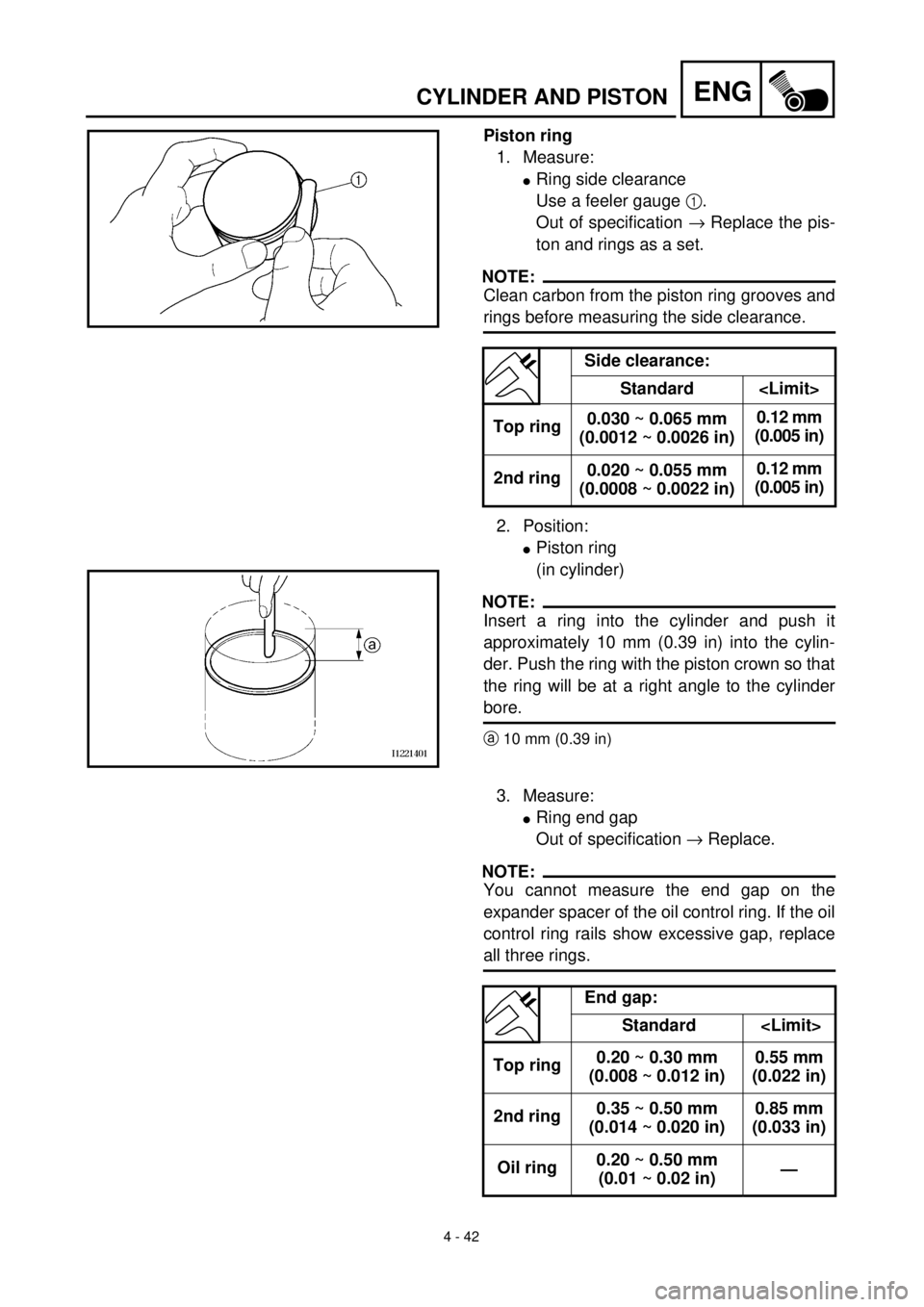
1. Measure:
l
Ring side clearance
Use a feeler gauge
1
.
Out of specification
®
Replace the pis-
ton and rings as a set.
NOTE:
Clean carbon from the piston ring grooves and
rings before measuring the side clearance.
2. Position:
l
Piston ring
(in cylinder)
NOTE:
Insert a ring into the cylinder and push it
approximately 10 mm (0.39 in) into the cylin-
der. Push the ring with the piston crown so that
the ring will be at a right angle to the cylinder
bore.
a
10 mm (0.39 in)
Side clearance:
Standard
Top ring0.030 ~ 0.065 mm
(0.0012 ~ 0.0026 in)0.12 mm
(0.005 in)
2nd ring0.020 ~ 0.055 mm
(0.0008 ~ 0.0022 in)0.12 mm
(0.005 in)
3. Measure:
l
Ring end gap
Out of specification
®
Replace.
NOTE:
You cannot measure the end gap on the
expander spacer of the oil control ring. If the oil
control ring rails show excessive gap, replace
all three rings.
End gap:
Standard
Top ring0.20 ~ 0.30 mm
(0.008 ~ 0.012 in)0.55 mm
(0.022 in)
2nd ring0.35 ~ 0.50 mm
(0.014 ~ 0.020 in)0.85 mm
(0.033 in)
Oil ring0.20 ~ 0.50 mm
(0.01 ~ 0.02 in)—
Page 322 of 626

4 - 43
ENG
CYLINDER AND PISTON
Piston pin
1. Inspect:
l
Piston pin
Blue discoloration/grooves
®
Replace,
then inspect the lubrication system.
2. Measure:
l
Piston pin-to-piston clearance
ASSEMBLY AND INSTALLATION
Piston
1. Install:
l
Piston rings
Onto the piston.
NOTE:
l
Be sure to install the piston rings so that the
manufacturer’s marks or numbers are
located on the upper side of the rings.
l
Lubricate the piston and piston rings liberally
with engine oil.
Measurement steps:
l
Measure the outside diameter (piston pin)
a
.
If out of specification, replace the piston
pin.
Outside diameter (piston pin):
18.991 ~ 19.000 mm
(0.7477 ~ 0.7480 in)
l
Measure the inside diameter (piston)
b
.
Inside diameter (piston):
19.004 ~ 19.015 mm
(0.7482 ~ 0.7486 in)
l
Calculate the piston pin-to-piston clear-
ance with the following formula.
Piston pin-to-piston clearance =
Inside diameter (piston)
b
–
Outside diameter (piston pin)
a
l
If out of specification, replace the piston.
Piston pin-to-piston clearance:
0.004 ~ 0.024 mm
(0.00016 ~ 0.00094 in)
: 0.07 mm (0.003 in)
Page 324 of 626

4 - 44
ENG
CYLINDER AND PISTON
2. Position:
l
Top ring
l
2nd ring
l
Oil ring
Offset the piston ring end gaps as
shown.
a
Top ring end
b
2nd ring end
c
Oil ring end (upper)
d
Oil ring
e
Oil ring end (lower)
3. Install:
l
Piston
1
l
Piston pin
2
l
Piston pin clips
3
NOTE:
l
Apply engine oil onto the piston pin and pis-
ton.
l
Be sure that the arrow mark
a
on the piston
points to the exhaust side of the engine.
l
Before installing the piston pin clip, cover the
crankcase with a clean rag to prevent the
piston pin clip from falling into the crankcase.
l
Install the piston pin clips with their ends fac-
ing downward.
4. Lubricate:
l
Piston
l
Piston rings
l
Cylinder
NOTE:
Apply a liberal coating of engine oil.
Cylinder
1. Install:
l
Dowel pins
l
O-ring
l
Gasket
1
l
Cylinder
2
NOTE:
Install the cylinder with one hand while com-
pressing the piston rings with the other hand.
CAUTION:
l
Pass the timing chain
3 through the tim-
ing chain cavity.
lBe careful not to damage the timing chain
guide 4 during installation.
45¡
135¡135¡
a
b ced
3New
New
New