Page 130 of 626

2 - 21
SPEC
CABLE ROUTING DIAGRAM
EC240000
CABLE ROUTING DIAGRAM
1
Hose guide
2
Brake hose
3
Fuel tank breather hose
4
Oil tank breather hose
5
Clamp
6
“ENGINE STOP” button lead
7
Sub wire harness
8
TPS (throttle position
sensor) lead
9
Neutral switch lead
0
Oil hose
A
Hose holder
B
CDI magneto lead
C
Clutch cable
D
Cylinder head breather hose
E
Carburetor breather hose
F
Overflow hose
Pass the clutch cable through
the cable guide.
õ
Pass the fuel tank breather hose
between the handlebar and ten-
sion bar, then insert its end into
the hole of the number plate.
‚
Pass the decompression cable
and “ENGINE STOP” button
lead under the frame.
ë
Fasten the CDI magneto lead,
neutral switch lead and
“ENGINE STOP” button lead to
the frame with a plastic locking
tie and cut off the tie end.
ä
Pass the “ENGINE STOP” but-
ton lead along the inner side of
the oil tank breather hose.
ì
Fasten the sub wire harness
and “ENGINE STOP” button
lead to the frame in front of the
protector of the sub wire har-
ness with a plastic locking tie
and cut off the tie end.
í
Pass the cylinder head breather
hose along the right side of the
oil tank breather hose.
î
Pass the sub wire harness
between the engine brackets.
é
Fasten the sub wire harness
and “ENGINE STOP” button
lead to the frame at the rear of
the protector of the sub wire har-
ness with a plastic locking tie
and cut off the tie end.
Page 132 of 626

2 - 22
SPEC
CABLE ROUTING DIAGRAM
ï
Fasten the TPS lead (in the
sub wire harness) under the
frame so that it does not con-
tact the carburetor.
ð
Fasten the TPS lead under the
coupler to the frame with a
plastic locking tie.
ñ
Pass the carburetor breather
hose and overflow hose
between the connecting rod
and cross tube (frame).
÷
Fasten the neutral switch lead
and oil hose together with a
plastic locking tie and cut off
the tie end.
ö
Fasten the cylinder head
breather hose and neutral
switch lead to the frame with a
plastic locking tie.
¯
Fasten the neutral switch lead
to the frame with a plastic
band.
¸
Fasten the cylinder head
breather hose with the hose
holder.
Î
Pass the clutch cable through
the cable guide.
å
Fasten the neutral switch lead
and CDI magneto lead together
with a plastic band.
ê
Pass the clutch cable on the
inside the cylinder head
breather hose.
æ
Pass the cylinder head
breather hose along the inner
side of the radiator pipe.
è
Pass the radiator breather
hose from the right side of the
frame to the left side, over radi-
ator pipe 1, along the inner side
of radiator hose 4 and the radi-
ator, and between the lower
engine bracket, crankcase, oil
hose and the frame.
×Pass the clutch cable between
the frame and radiator and
over the lower boss on the radi-
ator.
Page 134 of 626
2 - 23
SPEC
ãPass the neutral switch lead and
CDI magneto lead over the middle
radiator mounting boss. Then, pass
the decompression cable under the
middle radiator mounting boss and
along the left side of the neutral
switch lead and CDI magneto lead.
ôFit the brake hose into the guide on
the protector.
çFasten the ignition coil lead (in the
sub wire harness) on the upper
inside of the frame and cut off the
tie end.
óPass the ignition coil lead (in the
sub wire harness) under the cush-
ion bracket (frame).Fasten the ignition coil lead (in the
sub wire harness) to the frame
and cut off the tie end.
Pass the carburetor breather
hoses and overflow hose so that
all there hoses do not contact the
rear shock absorber.
CABLE ROUTING DIAGRAM
Page 136 of 626

2 - 24
SPECCABLE ROUTING DIAGRAM
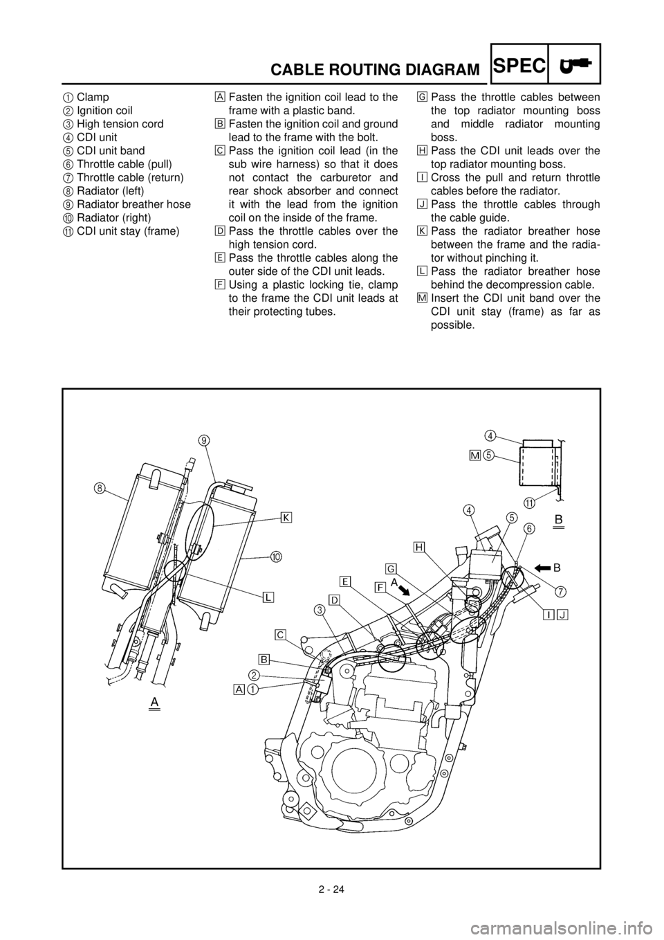
1Clamp
2Ignition coil
3High tension cord
4CDI unit
5CDI unit band
6Throttle cable (pull)
7Throttle cable (return)
8Radiator (left)
9Radiator breather hose
0Radiator (right)
ACDI unit stay (frame)Fasten the ignition coil lead to the
frame with a plastic band.
õFasten the ignition coil and ground
lead to the frame with the bolt.
‚Pass the ignition coil lead (in the
sub wire harness) so that it does
not contact the carburetor and
rear shock absorber and connect
it with the lead from the ignition
coil on the inside of the frame.
ëPass the throttle cables over the
high tension cord.
äPass the throttle cables along the
outer side of the CDI unit leads.
ìUsing a plastic locking tie, clamp
to the frame the CDI unit leads at
their protecting tubes.íPass the throttle cables between
the top radiator mounting boss
and middle radiator mounting
boss.
îPass the CDI unit leads over the
top radiator mounting boss.
éCross the pull and return throttle
cables before the radiator.
ïPass the throttle cables through
the cable guide.
ðPass the radiator breather hose
between the frame and the radia-
tor without pinching it.
ñPass the radiator breather hose
behind the decompression cable.
÷Insert the CDI unit band over the
CDI unit stay (frame) as far as
possible.
Page 138 of 626
2 - 25
SPECCABLE ROUTING DIAGRAM
1Throttle cable
2Clamp
3Decompression cable
4Clutch cable
5Brake hose
6Hose guide
7“ENGINE STOP” button leadFasten the “ENGINE STOP” button lead to the handlebar with the
plastic band.
õPass the brake hose in front of the number plate.
Page 389 of 626

4 - 76
ENG
MAGNETO CDI
CDI-SCHWUNGRADMAGNETZÜNDER
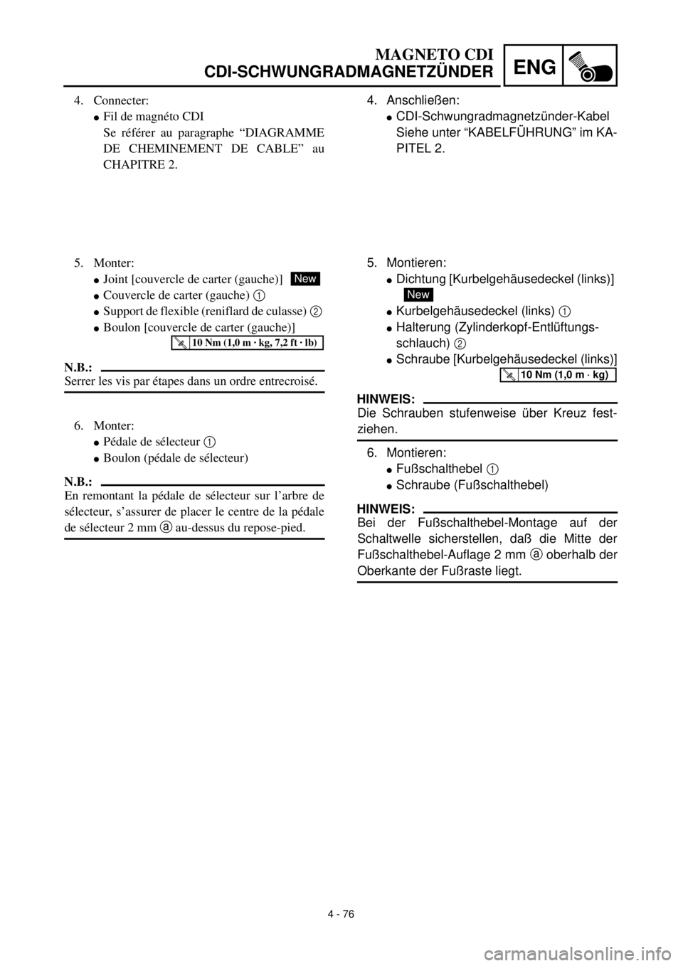
4. Anschließen:
lCDI-Schwungradmagnetzünder-Kabel
Siehe unter “KABELFÜHRUNG” im KA-
PITEL 2.
5. Montieren:
lDichtung [Kurbelgehäusedeckel (links)]
lKurbelgehäusedeckel (links) 1
lHalterung (Zylinderkopf-Entlüftungs-
schlauch) 2
lSchraube [Kurbelgehäusedeckel (links)]
HINWEIS:
Die Schrauben stufenweise über Kreuz fest-
ziehen.
6. Montieren:
lFußschalthebel 1
lSchraube (Fußschalthebel)
HINWEIS:
Bei der Fußschalthebel-Montage auf der
Schaltwelle sicherstellen, daß die Mitte der
Fußschalthebel-Auflage 2 mm a oberhalb der
Oberkante der Fußraste liegt.
New
T R..10 Nm (1,0 m · kg)
4. Connecter:
lFil de magnéto CDI
Se référer au paragraphe “DIAGRAMME
DE CHEMINEMENT DE CABLE” au
CHAPITRE 2.
5. Monter:
lJoint [couvercle de carter (gauche)]
lCouvercle de carter (gauche) 1
lSupport de flexible (reniflard de culasse) 2
lBoulon [couvercle de carter (gauche)]
N.B.:
Serrer les vis par étapes dans un ordre entrecroisé.
New
T R..10 Nm (1,0 m · kg, 7,2 ft · lb)
6. Monter:
lPédale de sélecteur 1
lBoulon (pédale de sélecteur)
N.B.:
En remontant la pédale de sélecteur sur l’arbre de
sélecteur, s’assurer de placer le centre de la pédale
de sélecteur 2 mm a au-dessus du repose-pied.
Page 554 of 626
6 - 1
–+ELECELECTRICAL COMPONENTS AND WIRING DIAGRAM
EC600000
ELECTRICAL
EC610000
ELECTRICAL COMPONENTS AND WIRING DIAGRAM
EC611000
ELECTRICAL COMPONENTS
1“ENGINE STOP” button
2TPS (throttle position sensor)
3Neutral switch
4CDI magneto
5Ignition coil
6Spark plug
7CDI unitCOLOR CODE
B...................... Black
Br .................... Brown
G ..................... Green
L ...................... Blue
O ..................... Orange
P...................... Pink
R ..................... Red
EC612000
WIRING DIAGRAM
7
15
6
2 3 4
LY
BYL
B/LL
G
P
W
R
Y
B
G
BR PBrWG
RB Br WP
R/W WL/W SbW R/W Sb L/WY
B/LL Sb B OY
LB/L B OSbSb
L/WR/W
WSb
B/L
B/WB/W
B/WB/W
Br
BB
LBBY
O
Sb .................... Sky blue
W ..................... White
Y ...................... Yellow
B/L ................... Black/Blue
B/W .................. Black/White
L/W .................. Blue/White
R/W .................. Red/White
6
Page 561 of 626

–+ELEC
ZÜNDANLAGE
ZÜNDANLAGE
FEHLERSUCHE
Folgendes Diagramm hilft zündanlagen- und zündkerzenbedingte Motorstörungen zu beheben.
* Nur wenn der Zündfunkenstreckentester verwendet wird
HINWEIS:
l
Die folgenden Teile vor Beginn der Störungsbeseitigung ausbauen.
1) Sitz
2) Kraftstofftank
l
Folgendes Spezialwerkzeug verwenden.
Zündfunkenstrecke
kontrollieren*Zündkerze reinigen
oder erneuern.
Kabelanschlüsse der
gesamten Zündenlage
kontrollieren.Erneuern oder instand
setzen.
Motorstoppschalter
“ENGINE STOP”
kontrollieren.Erneuern.
Zündspule kontrollieren. Primärspule Erneuern.
Sekundär-
spuleErneuern.
CDI-Schwungradmagnet-
zünder kontrollieren.Impulsgeber Erneuern.
Erregerspule Erneuern.
Leerlaufschalter
kontrollieren.Erneuern oder instand
setzen.
CDI-Zündbox erneuern.
Zündfunkenstreckentester
YM-34487
Zündprüfer
90890-06754
Taschen-Multimeter
YU-3112-C/90890-03112
Kein Zündfunke
In Ordnung
In Ordnung
In Ordnung
In Ordnung
Zündfunke
Nicht in Ordnung
In Ordnung
Nicht in Ordnung
Nicht in Ordnung
Nicht in Ordnung
Nicht in Ordnung
Nicht in Ordnung
Nicht in Ordnung
6 - 3