Page 166 of 626

3 - 12
INSP
ADJ
AIR FILTER CLEANING
EC35G040
AIR FILTER CLEANING
NOTE:
Proper air filter maintenance is the biggest key
to preventing premature engine wear and
damage.
CAUTION:
Never run the engine without the air filter
element in place; this would allow dirt and
dust to enter the engine and cause rapid
wear and possible engine damage.
1. Remove:
lSeat
lFitting bolt 1
lWasher 2
lAir filter element 3
lFilter guide 4
2. Clean:
lAir filter element
Clean them with solvent.
NOTE:
After cleaning, remove the remaining solvent
by squeezing the element.
CAUTION:
lDo not twist the element when squeezing
the element.
lLeaving too much of solvent in the ele-
ment may result in poor starting.
3. Inspect:
lAir filter element
Damage ® Replace.
4. Apply:
lFoam-air-filter oil or engine oil to the ele-
ment.
NOTE:
Squeeze out the excess oil. Element should
be wet but not dripping.
5. Install:
lFilter guide 1
NOTE:
Align the projection a on filter guide with the
hole b in air filter element.
Page 168 of 626
3 - 13
INSP
ADJ
ENGINE OIL LEVEL INSPECTION
6. Apply:
lLithium soap base grease
On the matching surface a on air filter
element.
7. Install:
lAir filter element 1
lWasher
lFitting bolt
NOTE:
Align the projection a on filter guide with the
hole b in air filter case.
T R..2 Nm (0.2 m · kg, 1.4 ft · lb)
ENGINE OIL LEVEL INSPECTION
1. Stand the motorcycle on a level surface.
NOTE:
lWhen checking the oil level make sure that
the motorcycle is upright.
lPlace the motorcycle on a suitable stand.
WARNING
Never remove the oil tank cap just after
high speed operation. The heated oil could
spurt out. causing danger. Wait until the oil
cools down to approximately 70 ˚C (158 ˚F).
2. Idle the engine more than 3 minutes
while keeping the motorcycle upright.
Then stop the engine and inspect the oil
level.
3. Remove:
lOil tank cap 1
Page 170 of 626

3 - 14
INSP
ADJ
4. Inspect:
lOil level
Oil level should be between maximum
a and minimum b marks.
Oil level low ® Add oil to proper level.
NOTE:
When inspecting the oil level, do not screw the
oil level gauge into the oil tank.
Insert the gauge lightly.
(For USA and CDN)
CAUTION:
lDo not add any chemical additives.
Engine oil also lubricates the clutch and
additives could cause clutch slippage.
lDo not allow foreign material to enter the
crankcase.
(Except for USA and CDN)
CAUTION:
lDo not add any chemical additives or use
oils with a grade of CD a or higher.
lDo not use oils labeled “ENERGY CON-
SERVING II” b or higher. Engine oil also
lubricates the clutch and additives could
cause clutch slippage.
lDo not allow foreign materials to enter the
crankcase.
Recommended oil:
At 5 ˚C (40 ˚F) or higher
Yamalube 4 (20W-40) or SAE
20W-40 type SH motor oil
(Non-Friction modified)
At 15 ˚C (60 ˚F) or lower õ
Yamalube 4 (10W-30) or SAE
10W-30 type SH motor oil
(Non-Friction modified)
and/or
Yamalube 4-R (15W-50)
(Non-Friction modified)
Recommended oil:
Refer to the following chart for
selection of oils which are suited
to the atmospheric temperatures.
Recommended engine oil classi-
fication:
API STANDARD:
API “SH” or higher grade
(Designed primarily for motor-
cycles)-20
-4-10
140
3010
5020
6830
8640 50
104
122¡CTemp.
¡F
10W-30
10W-40
20W-40
20W-50
15W-40
a
b
ENGINE OIL LEVEL INSPECTION
Page 172 of 626
3 - 15
INSP
ADJ
ENGINE OIL REPLACEMENT
5. Start the engine and let it warm up for
several minutes.
CAUTION:
When the oil tank is empty, never start the
engine.
6. Idle the engine more than 10 seconds
while keeping the motorcycle upright.
Then stop the engine and add the oil to
the maximum level.
7. Install:
lOil tank cap
ENGINE OIL REPLACEMENT
1. Start the engine and let it warm up for
several minutes.
2. Stop the engine and place an oil pan
under the drain bolt.
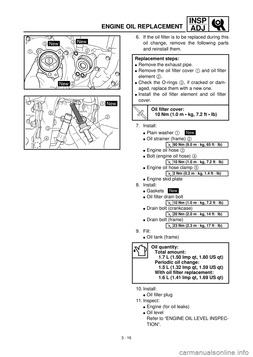
3. Remove:
lOil filler plug 1
lDrain bolt (with gasket) 2
lDrain bolt (with gasket) 3
lOil filter drain bolt (O-ring) 4
Drain the crankcase and oil tank
(frame) of its oil.
4. Remove:
lEngine skidplate
lEngine oil hose clamp 1
lBolt (engine oil hose) 2
lEngine oil hose 3
lOil strainer (frame) 4
5. Clean:
lOil strainer (frame)
Page 174 of 626

3 - 16
INSP
ADJ
ENGINE OIL REPLACEMENT
6. If the oil filter is to be replaced during this
oil change, remove the following parts
and reinstall them.
7. Install:
lPlain washer 1
lOil strainer (frame) 2
lEngine oil hose 3
lBolt (engine oil hose) 4
lEngine oil hose clamp 5
lEngine skid plate
8. Install:
lGaskets
lOil filter drain bolt
lDrain bolt (crankcase)
lDrain bolt (frame)
9. Fill:
lOil tank (frame)
10. Install:
lOil filler plug
11. Inspect:
lEngine (for oil leaks)
lOil level
Refer to “ENGINE OIL LEVEL INSPEC-
TION”. Replacement steps:
lRemove the exhaust pipe.
lRemove the oil filter cover 1 and oil filter
element 2.
lCheck the O-rings 3, if cracked or dam-
aged, replace them with a new one.
lInstall the oil filter element and oil filter
cover.
T R..
Oil filter cover:
10 Nm (1.0 m • kg, 7.2 ft • lb)
Oil quantity:
Total amount:
1.7 L (1.50 Imp qt, 1.80 US qt)
Periodic oil change:
1.5 L (1.32 Imp qt, 1.59 US qt)
With oil filter replacement:
1.6 L (1.41 Imp qt, 1.69 US qt)
New
T R..90 Nm (9.0 m · kg, 65 ft · lb)
T R..10 Nm (1.0 m · kg, 7.2 ft · lb)
T R..2 Nm (0.2 m · kg, 1.4 ft · lb)
New
T R..10 Nm (1.0 m · kg, 7.2 ft · lb)
T R..20 Nm (2.0 m · kg, 14 ft · lb)
T R..23 Nm (2.3 m · kg, 17 ft · lb)
Page 176 of 626

3 - 17
INSP
ADJ
PILOT SCREW ADJUSTMENT
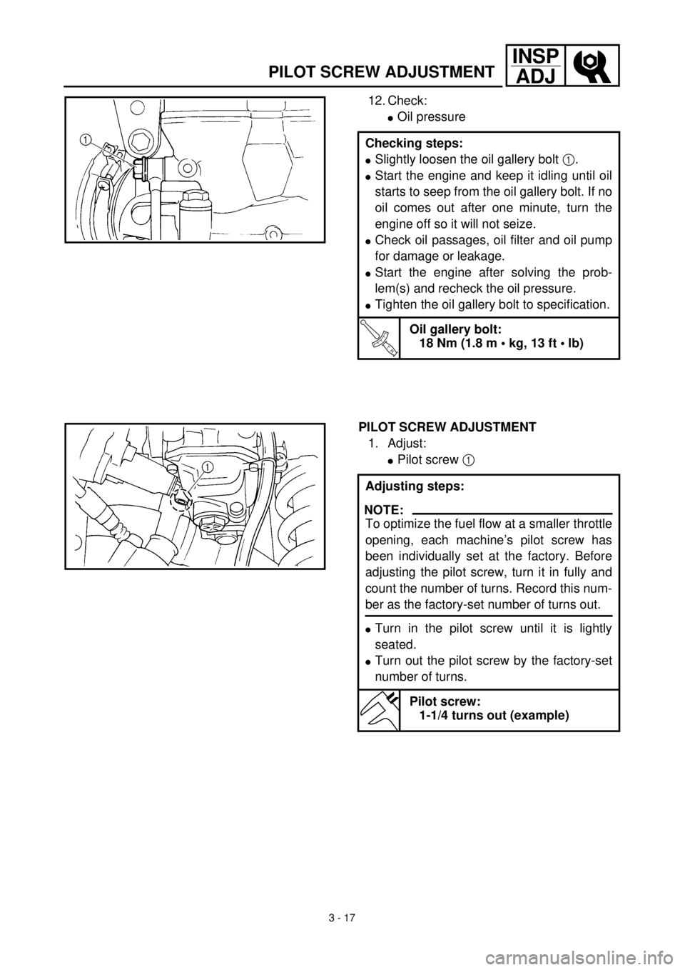
12. Check:
lOil pressure
Checking steps:
lSlightly loosen the oil gallery bolt 1.
lStart the engine and keep it idling until oil
starts to seep from the oil gallery bolt. If no
oil comes out after one minute, turn the
engine off so it will not seize.
lCheck oil passages, oil filter and oil pump
for damage or leakage.
lStart the engine after solving the prob-
lem(s) and recheck the oil pressure.
lTighten the oil gallery bolt to specification.
T R..
Oil gallery bolt:
18 Nm (1.8 m • kg, 13 ft • lb)
PILOT SCREW ADJUSTMENT
1. Adjust:
lPilot screw 1
Adjusting steps:
NOTE:
To optimize the fuel flow at a smaller throttle
opening, each machine’s pilot screw has
been individually set at the factory. Before
adjusting the pilot screw, turn it in fully and
count the number of turns. Record this num-
ber as the factory-set number of turns out.
lTurn in the pilot screw until it is lightly
seated.
lTurn out the pilot screw by the factory-set
number of turns.
Pilot screw:
1-1/4 turns out (example)
Page 184 of 626

3 - 21
INSP
ADJ
VALVE CLEARANCE ADJUSTMENT
l
Round off the last digit of the installed pad
number to the nearest increment.
Last digit of pad
numberRounded value
0 or 2 0
5(NOT ROUNDED
OFF)
810
EXAMPLE:
Installed pad number = 148
Rounded off value = 150
NOTE:
Pads can only be selected in 0.05 mm incre-
ments.
l
Locate the rounded-off value and the
measured valve clearance in the chart
“PAD SELECTION TABLE”. The field
where these two coordinates intersect
shows the new pad number to use.
NOTE:
Use the new pad number only as a guide
when verifying the valve clearance adjust-
ment.
l
Install the new pads
0
and the valve lift-
ers
A
.
NOTE:
l
Apply the engine oil on the valve lifters.
l
Apply the molybdenum disulfide oil on the
valve stem ends.
l
Valve lifter must turn smoothly when
rotated with a finger.
l
Be careful to reinstall valve lifters and
pads in their original place.
l
Install the decompression shaft
B
, plain
washer
C
, bolt
D
, guide
E
, bolt
F
and
decompression cable
G
.
NOTE:
Apply the engine oil on the decompression
shaft.
T R..
Bolt (decompression shaft):
7 Nm (0.7 m • kg, 5.1 ft • lb)
Bolt (guide):
10 Nm (1.0 m • kg, 7.2 ft • lb)
Page 208 of 626
3 - 32
INSP
ADJ
DRIVE CHAIN SLACK ADJUSTMENT
5. Install:
lDrive chain 1
lJoint 2
lMaster link clip 3
CAUTION:
Be sure to install the master link clip to the
direction as shown.
aTurning direction
6. Lubricate:
lDrive chain
Drive chain lubricant:
SAE 10W-30 motor oil or suit-
able chain lubricants
New
EC36A060
DRIVE CHAIN SLACK ADJUSTMENT
1. Elevate the rear wheel by placing the
suitable stand under the engine.
2. Check:
lDrive chain slack a
Above the seal guard installation bolt.
Out of specification ® Adjust.
NOTE:
Before checking and/or adjusting, rotate the
rear wheel through several revolutions and
check the slack several times to find the tight-
est point. Check and/or adjust chain slack with
rear wheel in this “tight chain” position.
Drive chain slack:
40 ~ 50 mm (1.6 ~ 2.0 in)