2001 YAMAHA YZ250LC clutch
[x] Cancel search: clutchPage 14 of 578

EC083000
MANUAL FORMAT
All of the procedures in this manual are organized in a sequential, step-by-step format. The information
has been complied to provide the mechanic with an easy to read, handy reference that contains com-
prehensive explanations of all disassembly, repair, assembly, and inspection operations.
In this revised format, the condition of a faulty component will precede an arrow symbol and the course
of action required will follow the symbol, e.g.,
9Bearings
Pitting/DamageÕReplace.
EC084002
HOW TO READ DESCRIPTIONS
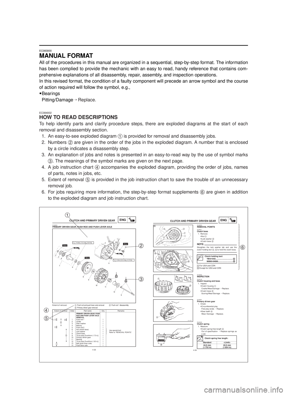
To help identify parts and clarify procedure steps, there are exploded diagrams at the start of each
removal and disassembly section.
1. An easy-to-see exploded diagram 1is provided for removal and disassembly jobs.
2. Numbers 2are given in the order of the jobs in the exploded diagram. A number that is enclosed
by a circle indicates a disassembly step.
3. An explanation of jobs and notes is presented in an easy-to-read way by the use of symbol marks
3. The meanings of the symbol marks are given on the next page.
4. A job instruction chart 4accompanies the exploded diagram, providing the order of jobs, names
of parts, notes in jobs, etc.
5. Extent of removal 5is provided in the job instruction chart to save the trouble of an unnecessary
removal job.
6. For jobs requiring more information, the step-by-step format supplements 6are given in addition
to the exploded diagram and job instruction chart.
4-33
CLUTCH AND PRIMARY DRIVEN GEARENG
Extent of removal Order Part name Q’ty RemarksPRIMARY DRIVEN GEAR, PUSHROD AND PUSH LEVER AXLE
REMOVAL1 Push rod 1 1
2 Circlip 1
3 Plain washer 1
4
Bearing 15 Push rod 2 1
6 Nut (clutch boss) 1
Use special tool.
7Lock washer1
Refer to “REMOVAL POINTS”.
8 Clutch boss 1
9Thrust plate [D=ø44mm (1.73 in)]1
10 Primary driven gear 1
11 Bearing 1
12
Thrust plate [D=ø42mm (1.65 in)]1
13 Bolt (push lever axle) 1
14 Push lever axle 1
EC498200PRIMARY DRIVEN GEAR, PUSH ROD AND PUSH LEVER AXLE
Extent of removal:1Push rod and push lever axle removal2Push rod 1 disassembly3Primary driven gear removal
23
1
1
1
ü
ï
ý
ï
þ
3
75 Nm (7.5 m•kg, 54 ft•lb)
6 Nm (0.6 m•kg, 4.3 ft•lb)
4-34
CLUTCH AND PRIMARY DRIVEN GEARENGEC493000REMOVAL POINTSEC483211Clutch boss1. Remove:
9Nut 1
9Lock washer 2
9Clutch boss 3
NOTE:Straighten the lock washer tab and use the
clutch holding tool 4, 5to hold the clutch boss.
ŒFor USA and CDN
ºExcept for USA and CDN
EC494000INSPECTIONEC484100Clutch housing and boss1. Inspect:
9Clutch housing 1
Cracks/Wear/Damage Õ Replace.
9Clutch boss 2
Scoring/Wear/Damage ÕReplace.
EC484201Primary driven gear1. Check:
9Circumferential play
Free play exists ÕReplace.
9Gear teeth a
Wear/ Damage ÕReplace.
EC484400Clutch spring1. Measure:
9Clutch spring free length a
Out of specification ÕReplace springs as
a set.
Clutch holding tool:
YM-91042................................4 4
90890-04086............................5 5
Clutch spring free length:
Standard
44.0 mm 42.0 mm
(1.732 in) (1.654 in)
Œ
ºŒü
ï
ï
ï
ï
ï
ï
ï
ý
ï
ï
ï
ï
ï
ï
ï
þ
1
2
3
4
56
5MW-9-30-0 7/5/00 2:14 PM Page 12
Page 22 of 578

CHAPTER 4
ENGINE
SEAT, FUEL TANK AND SIDE
COVERS.....................................................4-1
EXHAUST PIPE AND SILENCER..............4-3
RADIATOR..................................................4-4
CARBURETOR AND REED VALVE...........4-7
CYLINDER HEAD , CYLINDER AND
PISTON.....................................................4-17
CLUTCH AND PRIMARY DRIVEN
GEAR.......................................................4-32
KICK AXLE, SHIFT SHAFT AND
PRIMARY DRIVE GEAR...........................4-39
YPVS GOVERNOR...................................4-48
WATER PUMP..........................................4-50
CDI MAGNETO.........................................4-55
ENGINE REMOVAL..................................4-59
CRANKCASE AND CRANKSHAFT.........4-64
TRANSMISSION, SHIFT CAM AND
SHIFT FORK.............................................4-71
CHAPTER 5
CAHSSIS
FRONT WHEEL AND REAR WHEEL........5-1
FRONT BRAKE AND REAR BRAKE.......5-10
FRONT FORK...........................................5-27
HANDLEBAR............................................5-40
STEERING................................................5-47
SWINGARM..............................................5-52
REAR SHOCK ABSORBER.....................5-59
5MW-9-30-0 7/5/00 2:15 PM Page 20
Page 26 of 578

1-1
DESCRIPTION
GEN
INFO
EC100000
GENERAL INFORMATION
EC110000
DESCRIPTION
1Clutch lever
2“ENGINE STOP” button
3Front brake lever
4Throttle grip
5Radiator cap
6Fuel tank cap
7Kick starter
8Fuel tank
9Radiator
0Coolant drain bolt
qCheck bolt (Transmission oil level)
wRear brake pedal
eValve joint
rFuel cock
tStarter knob
yDrive chain
uAir cleaner
iShift pedal
oFront fork
NOTE:
9The machine you have purchased may differ
slightly from those shown in the following.
9Designs and specifications are subject to
change without notice.
1
5MW-9-30-1 7/3/00 1:36 PM Page 2
Page 39 of 578

1-8
SPECIAL TOOLS
GEN
INFO
Part number Tool name / How to use IIIustration
YU-33975, 90890-01403 Ring nut wrenchYU-33975 90890-01403
This tool is used when tighten the steering ring nut
to specification.
YM-1423, 90890-01423 Damper rod holder
YM-1423 90890-01423
Use this tool to remove and install the damper rod.
YM-01442, 90890-01442 Fork seal driver
YM-01442 90890-01442
This tool is used when install the fork oil seal.
YU-3112-C, 90890-03112 Yamaha pocket tester
YM-3112-C 90890-03112
Use this tool to inspect the coil resistance,
output voltage and amperage.
YU-8036-B Inductive tachometer
YU-8036-B 90890-03113
90890-03113 Engine tachometer
This tool is needed for observing engine rpm.
YM-91042, 90890-04086 Clutch holding tool
YM-91042 90890-04086
This tool is used to hold the clutch when removing
or installing the clutch boss securing nut.
YM-34487 Dynamic spark tester
YM-34487 90890-06754
90890-06754 Ignition checker
This instrument is necessary for checking the igni-
tion system components.
ACC-QUICK-GS-KT Quick gasket
®ACC-QUICK-GS-KT 90890-85505
90890-85505 YAMAHA Bond No. 1215
This sealant (Bond) is used for crankcase mating
surface, etc.
5MW-9-30-1 7/3/00 1:40 PM Page 15
Page 46 of 578

1-9
CONTROL FUNCTIONS
GEN
INFO
EC150000
CONTROL FUNCTIONS
EC151000
“ENGINE STOP” BUTTON
The “ENGINE STOP” button 1is located on the
left handlebar. Continue pushing the “ENGINE
STOP” button till the engine comes to a stop.
EC152000
CLUTCH LEVER
The clutch lever 1is located on the left handle-
bar; it disengages or engages the clutch. Pull
the clutch lever to the handlebar to disengage
the clutch, and release the lever to engage the
clutch. The lever should be pulled rapidly and
released slowly for smooth starts.
EC153000
SHIFT PEDAL
The gear ratios of the constant-mesh 5 speed
transmission are ideally spaced. The gears can
be shifted by using the shift pedal 1on the left
side of the engine.
EC154000
KICK STARTER
Rotate the kick starter 1away from the engine.
Push the starter down lightly with your foot until
the gears engage, then kick smoothly and force-
fully to start the engine. This model has a prima-
ry kick starter so the engine can be started in
any gear if the clutch is disengaged. In normal
practices, however, shift to neutral before start-
ing.
EC155001
THROTTLE GRIP
The throttle grip 1is located on the right han-
dlebar; it accelerates or decelerates the engine.
For acceleration, turn the grip toward you; for
deceleration, turn it away from you.
5MW-9-30-1 7/3/00 1:46 PM Page 22
Page 69 of 578

2-2
GENERAL SPECIFICATIONSSPEC
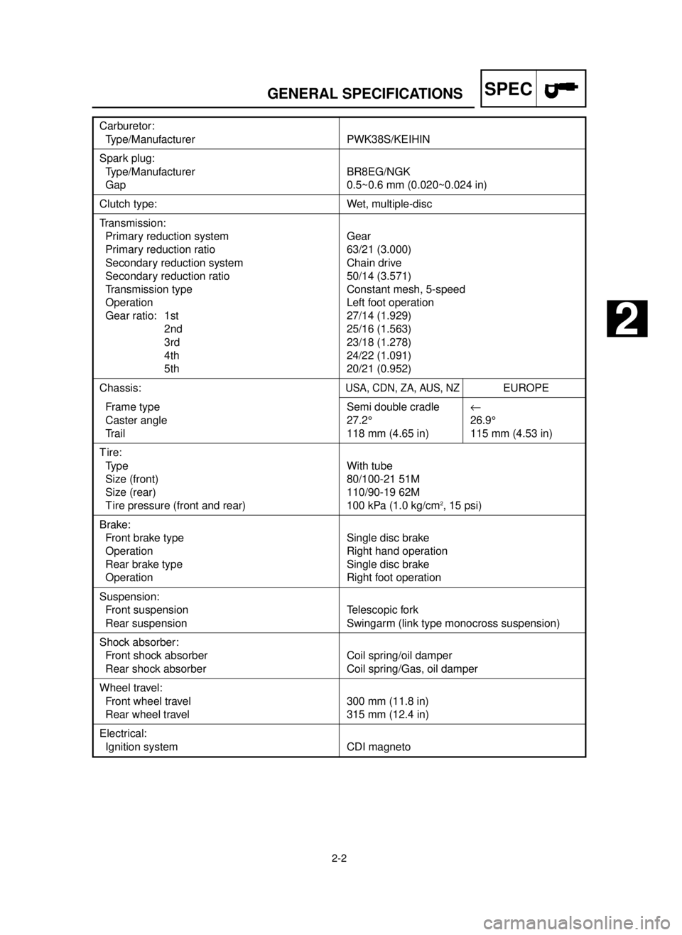
Carburetor:
Type/Manufacturer PWK38S/KEIHIN
Spark plug:
Type/Manufacturer BR8EG/NGK
Gap 0.5~0.6 mm (0.020~0.024 in)
Clutch type: Wet, multiple-disc
Transmission:
Primary reduction system Gear
Primary reduction ratio 63/21 (3.000)
Secondary reduction system Chain drive
Secondary reduction ratio 50/14 (3.571)
Transmission type Constant mesh, 5-speed
Operation Left foot operation
Gear ratio: 1st 27/14 (1.929)
2nd 25/16 (1.563)
3rd 23/18 (1.278)
4th 24/22 (1.091)
5th 20/21 (0.952)
Chassis:USA, CDN, ZA, AUS, NZEUROPE
Frame type Semi double cradle¬
Caster angle 27.2° 26.9°
Trail 118 mm (4.65 in) 115 mm (4.53 in)
T ire:
Type With tube
Size (front) 80/100-21 51M
Size (rear) 110/90-19 62M
T ire pressure (front and rear) 100 kPa (1.0 kg/cm2, 15 psi)
Brake:
Front brake type Single disc brake
Operation Right hand operation
Rear brake type Single disc brake
Operation Right foot operation
Suspension:
Front suspension Telescopic fork
Rear suspension Swingarm (link type monocross suspension)
Shock absorber:
Front shock absorber Coil spring/oil damper
Rear shock absorber Coil spring/Gas, oil damper
Wheel travel:
Front wheel travel 300 mm (11.8 in)
Rear wheel travel 315 mm (12.4 in)
Electrical:
Ignition system CDI magneto
2
5MW-9-30-2 7/3/00 2:19 PM Page 3
Page 70 of 578

2-3
MAINTENANCE SPECIFICATIONSSPEC
Item Standard Limit
Cylinder head:
Combustion chamber capacity 21.5 cm
3…
(0.757 Imp oz, 0.727 US oz)
Warp limit…
0.03 mm (0.0012 in)
Cylinder:
Bore size 66.400~66.414 mm 66.5 mm (2.618 in)
(2.6142~2.6147 in)
Taper limit…
0.05 mm (0.0020 in)
Out of round limit…
0.01 mm (0.0004 in)
Piston:
Piston size/ 66.352~66.367 mm…
(2.6120~2.6129 in)
Measuring point* 17.5 mm (0.69 in)…
Piston clearance 0.045~0.050 mm 0.1 mm (0.004 in)
(0.0018~0.0020 in)
Piston offset 1.5 mm (0.059 in)/EX-side…
Piston pin:
Piston pin outside diameter 17.995~18.000 mm 17.975 mm
(0.7085~0.7087 in) (0.7077 in)
Piston ring:
Sectional sketch Plain…
B=1.0 mm (0.039 in)…
T=2.55 mm (0.100 in)…
End gap (installed) 0.40~0.55 mm (0.016~0.022 in) 0.95 mm (0.037 in)
Side clearance (installed) : 1st
0.030~0.065 mm (0.0012~0.0026 in)0.1 mm (0.004 in)
: 2nd0.030~0.065 mm (0.0012~0.0026 in)0.1 mm (0.004 in)
Crankshaft:
Crank width “A” 59.95~60.00 mm (2.360~2.362 in)…
Runout limit “C” 0.03 mm (0.0012 in) 0.05 mm (0.0020 in)
Connecting rod big end
side clearance “D” 0.25~0.75 mm (0.010~0.030 in)…
Small end free play “F” 0.4~1.0 mm (0.016~0.039 in) 2.0 mm (0.08 in)
Clutch:
Friction plate thickness 2.9~3.1 mm (0.114~0.122 in) 2.8 mm (0.110 in)
Quantity 8 …
Clutch plate thickness 1.5~1.7 mm (0.059~0.067 in) …
Quantity 7 …
Warp limit … 0.2 mm (0.008 in)
Clutch spring free length 44.0 mm (1.732 in) 42.0 mm (1.654 in)
Quantity 6 …
Clutch housing thrust clearance 0.17~0.23 mm (0.007~0.009 in) …
Clutch housing radial clearance 0.030~0.055 mm (0.001~0.002 in) …
Clutch release method Inner push, cam push …
EC212000
MAINTENANCE SPECIFICATIONSEC212100
ENGINE
5MW-9-30-2 7/3/00 2:19 PM Page 4
Page 72 of 578

2-5
MAINTENANCE SPECIFICATIONSSPEC
Part to be tightened Thread size Q’tyT ightening torqueNm m•kg ft•lb
Spark plug M14 ´1.25 1 20 2.0 14
Cylinder head (nut) M 8 ´1.25 6 25 2.5 18
(stud) M 8 ´1.25 6 13 1.3 9.4
Cylinder (nut) M10 ´1.25 4 35 3.5 25
(stud) M10 ´1.25 4 13 1.3 9.4
Power valve :
Holder M 5 ´0.8 2 6 0.6 4.3
Link rod M 5 ´0.8 2 6 0.6 4.3
Push rod M 5 ´0.8 1 5 0.5 3.6
Thrust plate M 5 ´0.8 1 6 0.6 4.3
Side holder M 5 ´0.8 4 4 0.4 2.9
Link lever M 4 ´0.7 1 4 0.4 2.9
Pulley M 4 ´0.7 2 4 0.4 2.9
Cover M 5 ´0.8 4 4 0.4 2.9
Governor fork M 4 ´0.7 2 5 0.5 3.6
Housing M 5 ´0.8 4 5 0.5 3.6
Impeller M 8 ´1.25 1 14 1.4 10
Water pump housing cover M 6 ´1.0 4 10 1.0 7.2
Coolant drain bolt M 6 ´1.0 1 10 1.0 7.2
Radiator M 6 ´1.0 6 10 1.0 7.2
Radiator hose clamp M 6 ´1.0 8 1 0.1 0.7
Air filter element M 6 ´1.0 1 2 0.2 1.4
Carburetor joint M 6 ´1.0 5 10 1.0 7.2
Air filter case M 6 ´1.0 2 4 0.4 2.9
Air filter joint M 5 ´0.8 5 1 0.1 0.7
Reed valve M 3 ´0.5 4 1 0.1 0.7
Exhaust pipe M 6 ´1.0 2 12 1.2 8.7
Exhaust pipe stay (front) M 8 ´1.25 1 25 2.5 18
Exhaust pipe stay (rear) M 6 ´1.0 1 12 1.2 8.7
Silencer (front) M 6 ´1.0 1 12 1.2 8.7
Silencer (rear) M 6 ´1.0 1 7 0.7 5.1
Fiber (silencer) M 6 ´1.0 2 10 1.0 7.2
Crankcase M 6 ´1.0 11 14 1.4 10
Crankcase cover (left) M 6 ´1.0 5 8 0.8 5.8
Chain cover M 6 ´1.0 2 8 0.8 5.8
Crankcase cover (right) M 6 ´1.0 9 10 1.0 7.2
Bearing plate cover (drive axle left) M 6 ´1.0 2 10 1.0 7.2
Bearing plate cover (main axle right) M 6 ´1.0 2 10 1.0 7.2
Holder M 6 ´1.0 2 10 1.0 7.2
Oil drain bolt M12 ´1.5 1 20 2.0 14
Oil check bolt M 6 ´1.0 1 10 1.0 7.2
Kick starter M 8 ´1.25 1 30 3.0 22
Ratchet wheel stopper M 6 ´1.0 2 10 1.0 7.2
Clutch cover M 6 ´1.0 6 10 1.0 7.2
Primary drive gear M10 ´1.25 1 55 5.5 40
Clutch boss M20 ´1.0 1 75 7.5 54
5MW-9-30-2 7/3/00 2:20 PM Page 6