Page 364 of 578
5-2
CHASFRONT WHEEL AND REAR WHEEL
EC598100
REAR WHEEL
Extent of removal:1Rear wheel removal2Wheel bearing removal3Brake disc removal
Extent of removal Order Part name Q’ty Remarks
REAR WHEEL REMOVAL
Preparation for
Hold the machine by placing the
removalsuitable stand under the engine.
1 Nut (rear wheel axle) 1
2 Rear wheel axle 1
3 Chain puller 2
4 Rear wheel 1 Refer to “REMOVAL POINTS”.
5 Collar 2
6 Driven sprocket 1
7 Oil seal 2
8 Circlip 1
9 Bearing 2 Refer to “REMOVAL POINTS”.
10 Brake disk 1
2
13
3
w
Support the machine securely so there is no dan-
ger of it falling over.
125 Nm (12.5 m•kg, 90 ft•lb)
14 Nm (1.4 m•kg, 10 ft•lb)
42 Nm (4.2 m•kg, 30 ft•lb)
5MW-9-30-5A 7/6/00 8:21 AM Page 4
Page 366 of 578
5-3
CHASFRONT WHEEL AND REAR WHEEL
EC593000
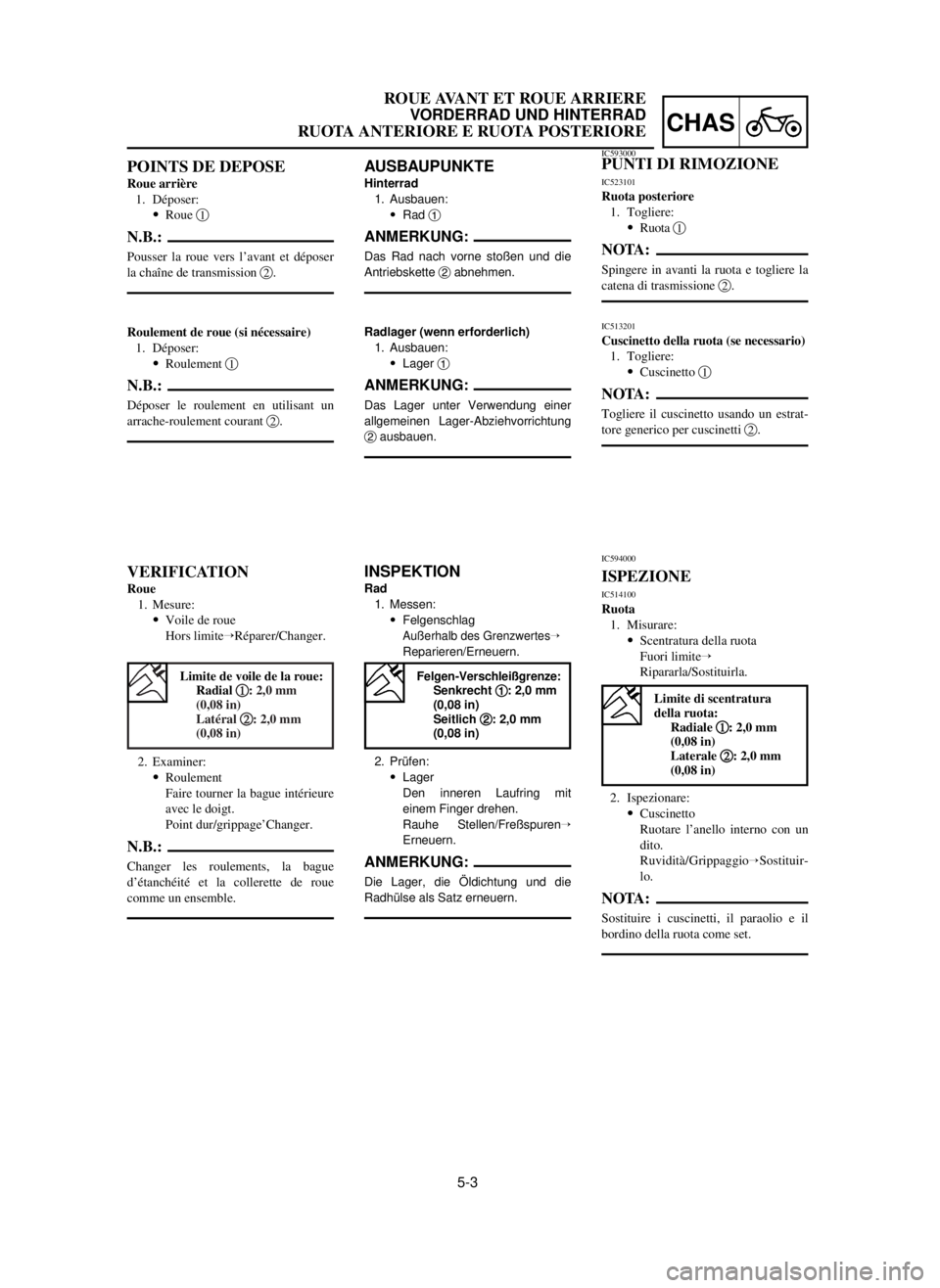
REMOVAL POINTS
EC523101
Rear wheel
1. Remove:
9Wheel 1
NOTE:
Push the wheel forward and remove the drive
chain 2.
EC513201
Wheel bearing (if necessary)
1. Remove:
9Bearing 1
NOTE:
Remove the bearing using a general bearing
puller 2.
EC594000
INSPECTION
EC514100
Wheel
1. Measure:
9Wheel runout
Out of limitÕRepair/Replace.
2. Inspect:
9Bearing
Rotate inner race with a finger.
Rough spot/SeizureÕReplace.
NOTE:
Replace the bearings, oil seal and wheel collar
as a set.
Wheel runout limit:
Radial 1 1
: 2.0mm (0.08 in)
Lateral 2 2
: 2.0mm (0.08 in)
5MW-9-30-5A 7/6/00 8:21 AM Page 6
Page 367 of 578

5-3
CHAS
ROUE AVANT ET ROUE ARRIERE
VORDERRAD UND HINTERRAD
RUOTA ANTERIORE E RUOTA POSTERIORE
AUSBAUPUNKTE
Hinterrad
1. Ausbauen:
9Rad 1
ANMERKUNG:
Das Rad nach vorne stoßen und die
Antriebskette 2abnehmen.
Radlager (wenn erforderlich)
1. Ausbauen:
9Lager 1
ANMERKUNG:
Das Lager unter Verwendung einer
allgemeinen Lager-Abziehvorrichtung
2ausbauen.
INSPEKTION
Rad
1. Messen:
9Felgenschlag
Außerhalb des GrenzwertesÕ
Reparieren/Erneuern.
2. Prüfen:
9Lager
Den inneren Laufring mit
einem Finger drehen.
Rauhe Stellen/FreßspurenÕ
Erneuern.
ANMERKUNG:
Die Lager, die Öldichtung und die
Radhülse als Satz erneuern.
POINTS DE DEPOSE
Roue arrière
1. Déposer:
9Roue 1
N.B.:
Pousser la roue vers l’avant et déposer
la chaîne de transmission 2.
Roulement de roue (si nécessaire)
1. Déposer:
9Roulement 1
N.B.:
Déposer le roulement en utilisant un
arrache-roulement courant 2.
VERIFICATION
Roue
1. Mesure:
9Voile de roue
Hors limiteÕRéparer/Changer.
2. Examiner:
9Roulement
Faire tourner la bague intérieure
avec le doigt.
Point dur/grippage’Changer.
N.B.:
Changer les roulements, la bague
d’étanchéité et la collerette de roue
comme un ensemble.
IC593000PUNTI DI RIMOZIONE
IC523101
Ruota posteriore
1. Togliere:
9Ruota 1
NOTA:
Spingere in avanti la ruota e togliere la
catena di trasmissione 2.
IC513201
Cuscinetto della ruota (se necessario)
1. Togliere:
9Cuscinetto 1
NOTA:
Togliere il cuscinetto usando un estrat-
tore generico per cuscinetti 2.
IC594000
ISPEZIONE
IC514100
Ruota
1. Misurare:
9Scentratura della ruota
Fuori limiteÕ
Ripararla/Sostituirla.
2. Ispezionare:
9Cuscinetto
Ruotare l’anello interno con un
dito.
Ruvidità/Grippaggio
ÕSostituir-
lo.
NOTA:
Sostituire i cuscinetti, il paraolio e il
bordino della ruota come set.
Limite de voile de la roue:
Radial 1 1
: 2,0 mm
(0,08 in)
Latéral 2 2
: 2,0 mm
(0,08 in)
Limite di scentratura
della ruota:
Radiale 1 1
: 2,0 mm
(0,08 in)
Laterale 2 2
: 2,0 mm
(0,08 in)
Felgen-Verschleißgrenze:Senkrecht 1 1
: 2,0 mm
(0,08 in)
Seitlich 2 2
: 2,0 mm
(0,08 in)
5MW-9-30-5A 7/6/00 8:21 AM Page 7
Page 369 of 578

5-4
CHAS
ROUE AVANT ET ROUE ARRIERE
VORDERRAD UND HINTERRAD
RUOTA ANTERIORE E RUOTA POSTERIORE
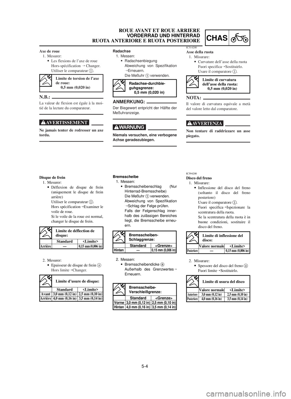
Disque de frein
1. Mesurer:
9Déflexion de disque de frein
(uniquement le disque de frein
arrière)
Utiliser le comparateur 1.
Hors spécificationÕExaminer le
voile de roue.
Si le voile de la roue est normal,
changer le disque de frein.
2. Mesurer:
9Epaisseur de disque de frein a
Hors limiteÕChanger.
Radachse
1. Messen:
9Radachsenbiegung
Abweichung von Spezifikation
ÕErneuern.
Die Meßuhr 1verwenden.
ANMERKUNG:
Der Biegewert entpricht der Hälfte der
Meßuhranzeige.
W
Niemals versuchen, eine verbogene
Achse geradezubiegen.
Axe de roue
1. Mesurer:
9Les flexions de l’axe de roue
Hors-spécification ÕChanger.
Utiliser le comparateur 1.
N.B.:
La valeur de flexion est égale à la moi-
tié de la lecture du comparateur.
XG
Ne jamais tenter de redresser un axe
tordu.
IC514200
Asse della ruota
1. Misurare:
9Curvature dell’asse della ruota
Fuori specificaÕSostituirlo.
Usare il comparatore 1.
NOTA:
Il valore di curvatura equivale a metà
del valore letto dal comparatore.
T
Non tentare di raddrizzare un asse
piegato.
Limite de torsion de l’axe
de roue:
0,5 mm (0,020 in)
Limite d’usure de disque:
Standard Avant3,0 mm (0,12 in) 2,5 mm (0,10 in)
Arrière 4,0 mm (0,16 in) 3,5 mm (0,14 in)
IC594200
Disco del freno
1. Misurare:
9Inflessione del disco del freno
(soltanto il disco del freno
posteriore)
Usare il comparatore 1.
Fuori specificaÕIspezionare la
scentratura della ruota.
Se la scentratura della ruota è in
buone condizioni, sostituire il
disco del freno.
2. Misurare:
9Spessore del disco del freno a
Fuori limiteÕSostituirlo.
Limite di curvatura
dell’asse della ruota:
0,5 mm (0,020 in)
Limite di usura del disco
Valore normaleAnteriore3,0 mm (0,12 in) 2,5 mm (0,10 in)Posteriore4,0 mm (0,16 in) 3,5 mm (0,14 in)
Bremsscheibe
1. Messen:
9Bremsscheibenschlag (Nur
Hinterrad-Bremsscheibe)
Die Meßuhr 1verwenden.
Abweichung von Spezifikation
ÕSchlag der Felge prüfen.
Falls der Felgenschlag inner-
halb des zulässigen Bereiches
liegt, die Bremsscheibe erneu-
ern.
2. Messen:
9Bremsscheibendicke a
Außerhalb des GrenzwertesÕ
Erneuern.
Radachse-durchbie-
guhgsgrenze:
0,5 mm (0,020 in)
Bremsscheibe-
Verschleißgrenze:
Standard
Vorne3,0 mm (0,12 in) 2,5 mm (0,10 in)
Hinten 4,0 mm (0,16 in) 3,5 mm (0,14 in)
Limite de déflection de
disque:
Standard
Arrière—0,15 mm (0,006 in)
Bremsscheiben-
Schlaggrenze:
Standard
Hinten —0,15 mm (0,006 in)
Limite di inflessione del
disco:
Valore normalePosteriore—0,15 mm (0,006 in)
5MW-9-30-5A 7/6/00 8:22 AM Page 9
Page 370 of 578
5-5
CHASFRONT WHEEL AND REAR WHEEL
EC595000
ASSEMBLY AND INSTALLATION
EC595101
Front wheel
1. Install:
9Bearing (left) 1
9Spacer 2
9Bearing (right) 3
9Oil seal 4
NOTE:
9Apply the lithium soap base grease on the
bearing and oil seal lip when installing.
9Use a socket that matches the outside diam-
eter of the race of the bearing.
9Left side of bearing shall be installed first.
9Install the oil seal with its manufacture’s
marks or numbers facing outward.
cC
Do not strike the inner race of the bearing.
Contact should be made only with the out-
er race.
2. Install:
9Brake disc 1
9Bolt (brake disc) 2
NOTE:
Tighten the bolts in stage, using a crisscross
pattern.
3. Install:
9Collar 1
NOTE:
9Apply the lithium soap base grease on the oil
seal lip.
9Install the collars with their projections afacing
the wheel.
4. Install:
9Wheel
NOTE:
Install the brake disc 1between the brake pads
2correctly.
12 Nm (1.2 m•kg, 8.7 ft•lb)
5MW-9-30-5A 7/6/00 8:23 AM Page 10
Page 374 of 578
5-7
CHASFRONT WHEEL AND REAR WHEEL
EC5251A0
Rear wheel
1. Install:
9Bearing (right) 1
9Circlip 2
9Spacer 3
9Bearing (left) 4
9Oil seal 5
NOTE:
9Apply the lithium soap base grease on the
bearing and oil seal lip when installing.
9Install the bearing with seal facing outward.
9Use a socket that matches the outside diam-
eter of the race of the bearing.
9Right side of bearing shall be installed first.
9Install the oil seal with its manufacture’s
marks or numbers facing outward.
cC
Do not strike the inner race of the bearing.
Contact should be made only with the out-
er race.
2. Install:
9Brake disc 1
9Bolt (brake disc) 2
NOTE:
Tighten the bolts in stage, using a crisscross
pattern.
9. Install:
9Hose cover 1
9Plain washer 2
9Bolt [hose cover (M8)] 3
9Bolt [hose cover (M6)] 4
16 Nm (1.6 m•kg, 11 ft•lb)
7 Nm (0.7 m•kg, 5.1 ft•lb)
14 Nm (1.4 m•kg, 1.0 ft•lb)
5MW-9-30-5A 7/6/00 8:24 AM Page 14
Page 376 of 578
5-8
CHASFRONT WHEEL AND REAR WHEEL
3. Install:
9Driven sprocket 1
9Bolt (driven sprocket) 2
9Plain washer (driven sprocket) 3
9Nut (driven sprocket) 4
NOTE:
Tighten the nuts in stage, using a crisscross pat-
tern.
4. Install:
9Collar 1
NOTE:
Apply the lithium soap base grease on the oil
seal lip.
5. Install:
9Wheel
NOTE:
Install the brake disc 1between the brake pads
2correctly.
6. Install:
9Drive chain 1
NOTE:
Push the wheel 2forward and install the drive
chain.
7. Install:
9Chain puller (left) 1
9Wheel axle 2
NOTE:
9Install the chain puller (left), and insert the
wheel axle from left side.
9Apply the lithium soap base grease on the
wheel axle.
42 Nm (4.2 m•kg, 30 ft•lb)
5MW-9-30-5A 7/6/00 8:25 AM Page 16
Page 410 of 578

5-25
CHASFRONT BRAKE AND REAR BRAKE
2. Install:
9Brake hose holder 1
9Screw (brake hose holder) 2
cC
After installing the brake hose holders,
make sure the brake hose does not contact
the spring (rear shock absorber). If it does,
correct its twist.
EC5A5600
Brake fluid
1. Fill:
9Brake fluid
Until the fluid level reaches “LOWER” level
line a.
w
9Use only the designated quality brake fluid:
otherwise, the rubber seals may deterio-
rate, causing leakage and poor brake per-
formance.
9Refill with the same type of brake fluid;
mixing fluids may result in a harmful chemi-
cal reaction and lead to poor performance.
9Be careful that water does not enter the
master cylinder when refilling. Water will
significantly lower the boiling point of the
fluid and may result in vapor lock.
cC
Brake fluid may erode painted surfaces or
plastic parts. Always clean up spilled fluid
immediately.
AFront
BRear
4 Nm (0.4 m•kg, 2.9 ft•lb)
Recommended brake fluid:
DOT #4
5MW-9-30-5A 7/6/00 9:00 AM Page 50