2001 YAMAHA YZ125LC check engine
[x] Cancel search: check enginePage 14 of 558

EC083000
MANUAL FORMAT
All of the procedures in this manual are organized in a sequential, step-by-step format. The informa-
tion has been complied to provide the mechanic with an easy to read, handy reference that contains
comprehensive explanations of all disassembly, repair, assembly, and inspection operations.
In this revised format, the condition of a faulty component will precede an arrow symbol and the
course of action required will follow the symbol, e.g.,
9Bearings
Pitting/DamageÕReplace.
EC084002
HOW TO READ DESCRIPTIONS
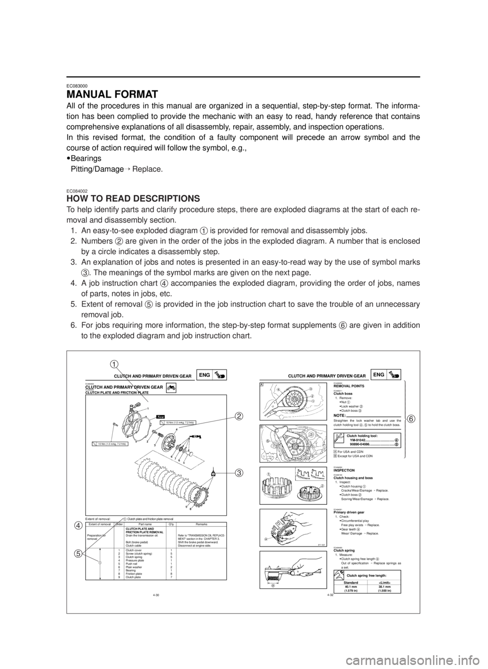
To help identify parts and clarify procedure steps, there are exploded diagrams at the start of each re-
moval and disassembly section.
1. An easy-to-see exploded diagram 1is provided for removal and disassembly jobs.
2. Numbers 2are given in the order of the jobs in the exploded diagram. A number that is enclosed
by a circle indicates a disassembly step.
3. An explanation of jobs and notes is presented in an easy-to-read way by the use of symbol marks
3. The meanings of the symbol marks are given on the next page.
4. A job instruction chart 4accompanies the exploded diagram, providing the order of jobs, names
of parts, notes in jobs, etc.
5. Extent of removal 5is provided in the job instruction chart to save the trouble of an unnecessary
removal job.
6. For jobs requiring more information, the step-by-step format supplements 6are given in addition
to the exploded diagram and job instruction chart.
4-30
ENGCLUTCH AND PRIMARY DRIVEN GEAR
Extent of removal Order Part name Q’ty Remarks
CLUTCH PLATE AND
FRICTION PLATE REMOVAL
Preparation for Drain the transmission oil.
Refer to “TRANSMISSION OIL REPLACE-removalMENT“ section in the CHAPTER 3.Bolt (brake pedal) Shift the brake pedal downward.
Clutch cable Disconnect at engine side.
1 Clutch cover 1
2 Screw (clutch spring) 5
3 Clutch spring 5
4 Pressure plate 1
5 Push rod 1
6 Plain washer 2
7 Bearing 1
8 Friction plate 8
9 Clutch plate 7
Extent of removal:1Clutch plate and friction plate removal
EC490000CLUTCH AND PRIMARY DRIVEN GEAREC498000CLUTCH PLATE AND FRICTION PLATE
1
10 Nm (1.0 m•kg, 7.2 ft•lb)
10 Nm (1.0 m•kg, 7.2 ft•lb)
4-32
ENGCLUTCH AND PRIMARY DRIVEN GEAREC493000REMOVAL POINTSEC483211Clutch boss1. Remove:
9Nut 1
9Lock washer 2
9Clutch boss 3
NOTE:Straighten the lock washer tab and use the
clutch holding tool 4, 5to hold the clutch boss.
Œ
For USA and CDN
º
Except for USA and CDN
EC494000INSPECTIONEC484100Clutch housing and boss1. Inspect:
9Clutch housing 1
Cracks/Wear/Damage Õ Replace.
9Clutch boss 2
Scoring/Wear/Damage ÕReplace.
EC484201Primary driven gear1. Check:
9Circumferential play
Free play exists ÕReplace.
9Gear teeth a
Wear/ Damage ÕReplace.
EC484400Clutch spring1. Measure:
9Clutch spring free length a
Out of specification ÕReplace springs as
a set.
Clutch holding tool:
YM-91042................................4 4
90890-04086............................5 5
Clutch spring free length:
Standard
40.1 mm 38.1 mm
(1.579 in) (1.500 in)
Œ
ºŒü
ï
ï
ï
ï
ï
ï
ï
ý
ï
ï
ï
ï
ï
ï
ï
þ
1
2
3
4
56
5MV-9-30-0 6/19/00 2:05 PM Page 12
Page 20 of 558

EC0A0000
CONTENTS
CHAPTER 1
GENERAL INFORMATION
DESCRIPTION............................................1-1
MACHINE IDENTIFICATION......................1-2
IMPORTANT INFORMATION.....................1-3
CHECKING OF CONNECTION..................1-6
SPECIAL TOOLS........................................1-7
CONTROL FUNCTIONS.............................1-9
FUEL AND ENGINE MIXING OIL.............1-12
STARTING AND BREAK-IN.....................1-13
TORQUE-CHECK POINTS.......................1-16
CLEANING AND STORAGE....................1-17
CHAPTER 2
SPECIFICATIONS
GENERAL SPECIFICATIONS....................2-1
MAINTENANCE SPECIFICATIONS...........2-3
GENERAL TORQUE SPECIFICATIONS..2-12
DEFINITION OF UNITS............................2-12
CABLE ROUTING DIAGRAM..................2-13
CHAPTER 3
REGULAR INSPECTION
AND ADJUSTMENTS
MAINTENANCE INTERVALS.....................3-1
PRE-OPERATION INSPECTION AND
MAINTENANCE..........................................3-4
ENGINE.......................................................3-5
CHASSIS...................................................3-17
ELECTRICAL............................................3-38
5MV-9-30-0 6/19/00 2:05 PM Page 18
Page 26 of 558

1-1
GEN
INFO
DESCRIPTION
EC100000
GENERAL INFORMATION
EC110000
DESCRIPTION
1Clutch lever
2”ENGINE STOP” button
3Front brake lever
4Throttle grip
5Radiator cap
6Fuel tank cap
7Kick starter
8Fuel tank
9Radiator
0Coolant drain bolt
qCheck bolt (Transmission oil level)
wRear brake pedal
eValve joint
rFuel cock
tAir cleaner
yDrive chain
uShift pedal
iStarter knob
oFront fork
NOTE:
9The machine you have purchased may differ
slightly from those shown in the following.
9Designs and specifications are subject to
change without notice.
1
5MV-9-30-1A 6/19/00 1:11 PM Page 2
Page 54 of 558

1-13
GEN
INFO
STARTING AND BREAK-IN
EC190000
STARTING AND BREAK-IN
cC
Before starting the machine, perform the
checks in the pre-operation check list.
w
Never start or run the engine in a closed
area. The exhaust fumes are poisonous;
they can cause loss of consciousness and
death in a very short time. Always operate
the machine in a well-ventilated area.
EC191001
STARTING A COLD ENGINE
1. Shift the transmission into neutral.
2. Turn the fuel cock to “ON” and full open the
starter knob (CHOKE).
3. With the throttle completely closed start the
engine by kicking the kick starter forcefully
with firm stroke.
4. Run the engine at idle or slightly higher until
it warms up: this usually takes about one or
two minutes.
5. The engine is warmed up when it responds
normally to the throttle with the starter knob
(CHOKE) turned off.
cC
Do not warm up the engine for extended peri-
ods.
EC193001
STARTING A WARM ENGINE
Do not operate the starter knob (CHOKE). Open
the throttle slightly and start the engine by kick-
ing the kick starter forcefully with firm stroke.
cC
Observe the following break-in procedures
during initial operation to ensure optimum
performance and avoid engine damage.
5MV-9-30-1B 6/20/0 5:11 PM Page 4
Page 56 of 558

1-14
GEN
INFO
STARTING AND BREAK-IN
EC194001
BREAK-IN PROCEDURES
1. Before starting the engine, fill the fuel tank
with a break-in oil-fuel mixture as follows.
2. Perform the pre-operation checks on the
machine.
3. Start and warm up the engine. Check the
idle speed, and check the operation of the
controls and the “ENGINE STOP” button.
4. Operate the machine in the lower gears at
moderate throttle openings for five to eight
minutes. Stop and check the spark plug con-
dition; it will show a rich condition during
break-in.
5. Allow the engine to cool. Restart the engine
and operate the machine as in the step
above for five minutes. Then, very briefly
shift to the higher gears and check full-throt-
tle response. Stop and check the spark
plug.
6. After again allowing the engine to cool,
restart and run the machine for five more
minutes. Full throttle and the higher gears
may be used, but sustained full-throttle op-
eration should be avoided. Check the spark
plug condition.
7. Allow the engine to cool, remove the top
end, and inspect the piston and cylinder.
Remove any high spots on the piston with
#600 grit wet sandpaper. Clean all compo-
nents and carefully reassemble the top end.
8. Drain the break-in oil-fuel mixture from the
fuel tank and refill with the specified mix.
9. Restart the engine and check the operation
of the machine throughout its entire operat-
ing range. Stop and check the spark plug
condition. Restart the machine and operate
it for about 10 to 15 more minutes. The ma-
chine will now be ready to race.
Mixing oil: Mixing ratio:
Yamalube “2-R” 15:1
5MV-9-30-1B 6/20/0 5:11 PM Page 6
Page 58 of 558

1-15
GEN
INFO
STARTING AND BREAK-IN
cC
9After the break-in or before each race, you
must check the entire machine for loose fit-
tings and fasteners as per “TORQUE-
CHECK POINTS”.
Tighten all such fasteners as required.
9When any of the following parts have been
replaced, they must be broken in.
CYLINDER AND CRANKSHAFT:
About one hour of break-in operation is
necessary.
PISTON, RING AND GEARS:
These parts require about 30 minutes of
break-in operation at half-throttle or less.
Observe the condition of the engine careful-
ly during operation.
5MV-9-30-1B 6/20/0 5:11 PM Page 8
Page 60 of 558

1-16
GEN
INFO
TORQUE-CHECK POINTS
EC1A0012
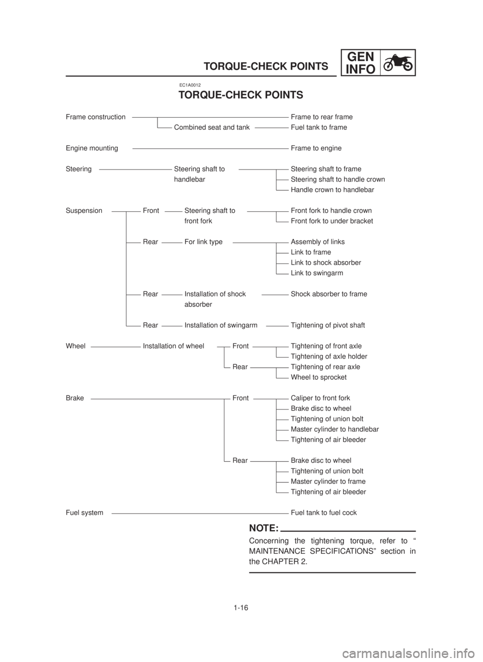
TORQUE-CHECK POINTS
Frame construction Frame to rear frame
Combined seat and tank Fuel tank to frame
Engine mounting Frame to engine
Steering Steering shaft to Steering shaft to frame
handlebar Steering shaft to handle crown
Handle crown to handlebar
Suspension Front Steering shaft to Front fork to handle crown
front fork Front fork to under bracket
Rear For link type Assembly of links
Link to frame
Link to shock absorber
Link to swingarm
Rear Installation of shock Shock absorber to frame
absorber
Rear Installation of swingarm Tightening of pivot shaft
Wheel Installation of wheel Front Tightening of front axle
Tightening of axle holder
Rear Tightening of rear axle
Wheel to sprocket
Brake Front Caliper to front fork
Brake disc to wheel
Tightening of union bolt
Master cylinder to handlebar
Tightening of air bleeder
Rear Brake disc to wheel
Tightening of union bolt
Master cylinder to frame
Tightening of air bleeder
Fuel system Fuel tank to fuel cock
NOTE:
Concerning the tightening torque, refer to “
MAINTENANCE SPECIFICATIONS” section in
the CHAPTER 2.
5MV-9-30-1B 6/20/0 5:12 PM Page 10
Page 77 of 558

2-10
SPECMAINTENANCE SPECIFICATIONS
Part to be tightened Thread size Q'tyT ightening torqueNm m•kg ft•lb
Rear brake master cylinder and frame M 6 ´1.0 2 10 1.0 7.2
Rear brake reservoir tank and frame M 6 ´1.0 1 7 0.7 5.1
Rear brake hose union bolt (caliper) M10 ´1.25 1 30 3.0 22
Rear brake hose union bolt (master cylinder) M10 ´1.25 1 30 3.0 22
Rear wheel axle and nut M20 ´1.5 1 125 12.5 90
Nipple (spoke) – 72 3 0.3 2.2
Driven sprocket and wheel hub M 8 ´1.25 6 42 4.2 30
Disc cover and rear brake caliper M 6 ´1.0 2 7 0.7 5.1
Protector and rear brake caliper M 6 ´1.0 2 7 0.7 5.1
Engine mounting:
Engine and frame (front) M10 ´1.25 1 69 6.9 50
Engine and frame (lower) M10 ´1.25 1 69 6.9 50
Engine bracket and frame M 8 ´1.25 2 34 3.4 24
Engine bracket and engine M 8 ´1.25 1 34 3.4 24
Pivot shaft and nut M16 ´1.5 1 85 8.5 61
Relay arm and swingarm M14 ´1.5 1 80 8.0 58
Relay arm and connecting rod M14 ´1.5 1 80 8.0 58
Connecting rod and frame M14 ´1.5 1 80 8.0 58
Rear shock absorber and frame M10 ´1.25 1 56 5.6 40
Rear shock absorber and relay arm M10 ´1.25 1 53 5.3 38
Rear frame and frame M 8 ´1.25 3 29 2.9 21
Swingarm and brake hose holder M 5 ´–4 4 0.4 2.9
Chain tensioner mounting M 8 ´1.25 2 19 1.9 13
Chain support and swingarm M 6 ´1.0 3 7 0.7 5.1
Seal guard and swingarm M 5 ´0.8 4 5 0.5 3.6
Fuel tank mounting M 6 ´1.0 2 10 1.0 7.2
Fuel tank and fuel cock M 6 ´1.0 2 7 0.7 5.1
Fuel tank and seat set bracket M 6 ´1.0 1 7 0.7 5.1
Fuel tank and hooking screw (fitting band) M 6 ´1.0 1 7 0.7 5.1
Fuel tank and fuel tank bracket M 6 ´1.0 4 7 0.7 5.1
Air scoop mounting M 6 ´1.0 8 3 0.3 2.2
Front fender mounting M 6 ´1.0 4 7 0.7 5.1
Rear fender mounting M 6 ´1.0 4 7 0.7 5.1
Side cover mounting M 6 ´1.0 4 7 0.7 5.1
Seat mounting M 6 ´1.0 2 7 0.7 5.1
Number plate M 6 ´1.0 1 7 0.7 5.1
NOTE:
s
s- marked portion shall be checked for torque tightening after break-in or before each race.
s
s
s s
s s
s s
s s
s s
s s
s s
s s
s s
s s
s s
s s
s s
s s
s s
s s
s s
s s
5MV-9-30-2A 6/19/00 1:15 PM Page 11