Page 8 of 558

5. GASOLINE IS HIGHLY FLAMMABLE.
Always turn off the engine while refuel-
ing. Take care to not spill any gasoline
on the engine or exhaust system.
Never refuel in the vicinity of an open
flame, or while smoking.
6. GASOLINE CAN CAUSE INJURY.
If you should swallow some gasoline,
inhale excess gasoline vapors, or allow
any gasoline to get into your eyes,
contact a doctor immediately. If any
gasoline spills onto your skin or cloth-
ing, immediately wash skin areas with
soap and water, and change your
clothes.
7. ONLY OPERATE THE MACHINE IN AN
AREA WITH ADEQUATE VENTILATION.
Never start the engine or let it run for
any length of time in an enclosed area.
Exhaust fumes are poisonous. These
fumes contain carbon monoxide,
which by itself is odorless and color-
less.
Carbon monoxide is a dangerous gas
which can cause unconsciousness or
can be lethal.
8. PARK THE MACHINE CAREFULLY;
TURN OFF THE ENGINE.
Always turn off the engine if you are
going to leave the machine. Do not
park the machine on a slope or soft
ground as it may fall over.
9. PROPERLY SECURE THE MACHINE
BEFORE TRANSPORTING IT.
When transporting the machine in an-
other vehicle, always be sure it is prop-
erly secured and in an upright position
and that the fuel cock is in the “OFF”
5MV-9-30-0 6/19/00 2:05 PM Page 6
Page 12 of 558

EC080000
HOW TO USE
THIS MANUAL
EC081000
PARTICULARLY IMPORTANT IN
FORMATION
Q
The Safety Alert Symbol means ATTENTION!
BECOME ALERT! YOUR SAFETY IS IN-
VOLVED!
w
Failure to follow WARNING instructions could re-
sult in severe injury or death to the machine op-
erator, a bystander, or a person inspecting or re-
pairing the machine.
cC
A CAUTION indicates special precautions that
must be taken to avoid damage to the machine.
NOTE:
A NOTE provides key information to make pro-
cedures easier or clearer.
EC082000
FINDING THE REQUIRED PAGE
1. This manual consists of seven chapters;
“General Information”, “Specifications”,
“Regular inspection and adjustments”,
“Engine”, “Chassis”, “Electrical” and
“Tuning”.
2. The table of contents is at the beginning of
the manual. Look over the general layout of
the book before finding then required chap-
ter and item.
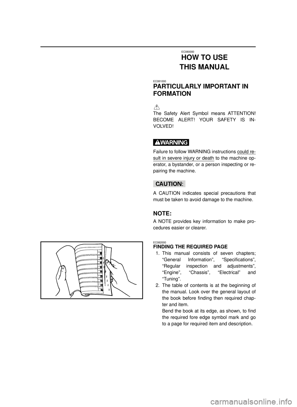
Bend the book at its edge, as shown, to find
the required fore edge symbol mark and go
to a page for required item and description.
5MV-9-30-0 6/19/00 2:05 PM Page 10
Page 14 of 558

EC083000
MANUAL FORMAT
All of the procedures in this manual are organized in a sequential, step-by-step format. The informa-
tion has been complied to provide the mechanic with an easy to read, handy reference that contains
comprehensive explanations of all disassembly, repair, assembly, and inspection operations.
In this revised format, the condition of a faulty component will precede an arrow symbol and the
course of action required will follow the symbol, e.g.,
9Bearings
Pitting/DamageÕReplace.
EC084002
HOW TO READ DESCRIPTIONS
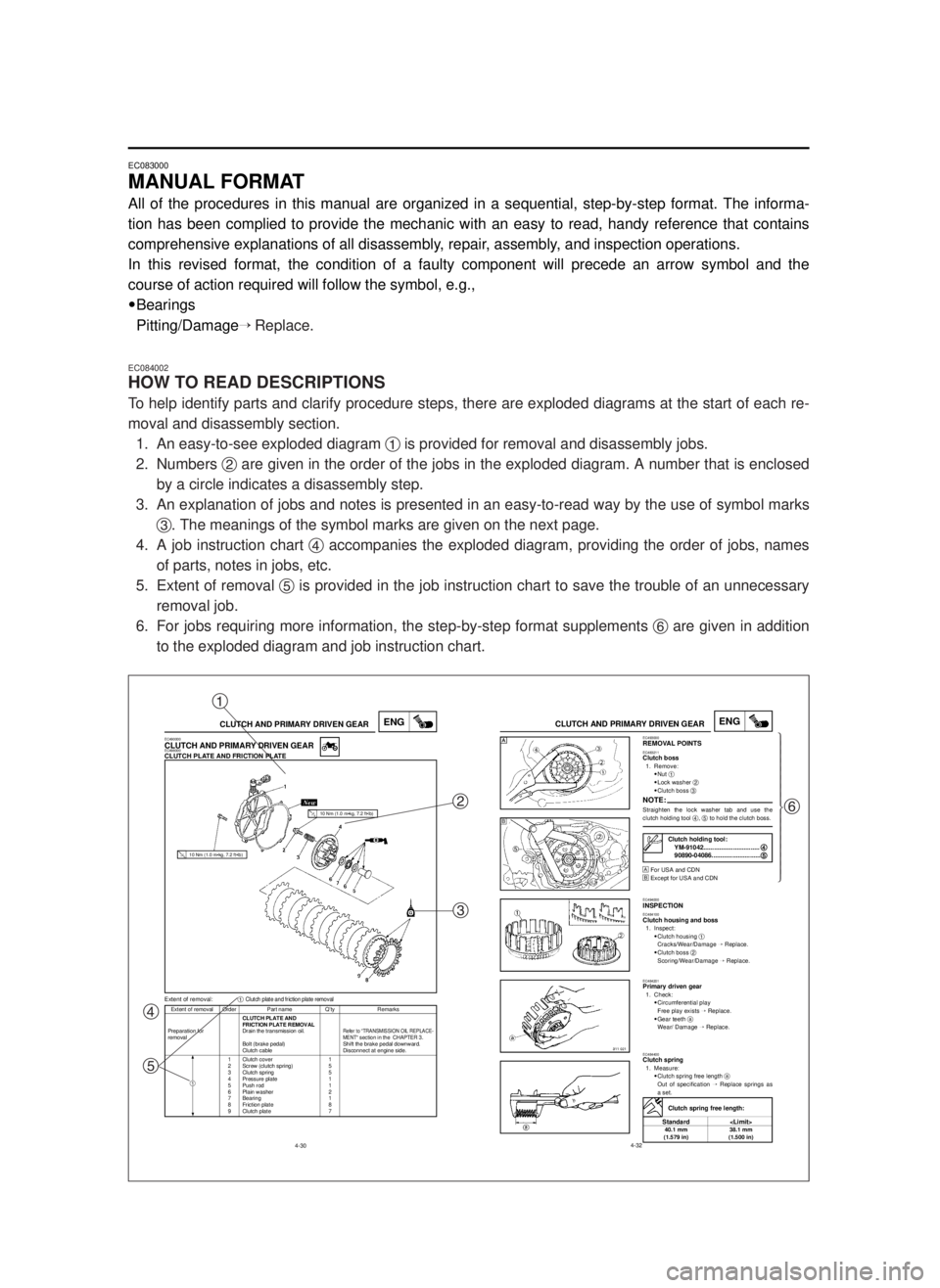
To help identify parts and clarify procedure steps, there are exploded diagrams at the start of each re-
moval and disassembly section.
1. An easy-to-see exploded diagram 1is provided for removal and disassembly jobs.
2. Numbers 2are given in the order of the jobs in the exploded diagram. A number that is enclosed
by a circle indicates a disassembly step.
3. An explanation of jobs and notes is presented in an easy-to-read way by the use of symbol marks
3. The meanings of the symbol marks are given on the next page.
4. A job instruction chart 4accompanies the exploded diagram, providing the order of jobs, names
of parts, notes in jobs, etc.
5. Extent of removal 5is provided in the job instruction chart to save the trouble of an unnecessary
removal job.
6. For jobs requiring more information, the step-by-step format supplements 6are given in addition
to the exploded diagram and job instruction chart.
4-30
ENGCLUTCH AND PRIMARY DRIVEN GEAR
Extent of removal Order Part name Q’ty Remarks
CLUTCH PLATE AND
FRICTION PLATE REMOVAL
Preparation for Drain the transmission oil.
Refer to “TRANSMISSION OIL REPLACE-removalMENT“ section in the CHAPTER 3.Bolt (brake pedal) Shift the brake pedal downward.
Clutch cable Disconnect at engine side.
1 Clutch cover 1
2 Screw (clutch spring) 5
3 Clutch spring 5
4 Pressure plate 1
5 Push rod 1
6 Plain washer 2
7 Bearing 1
8 Friction plate 8
9 Clutch plate 7
Extent of removal:1Clutch plate and friction plate removal
EC490000CLUTCH AND PRIMARY DRIVEN GEAREC498000CLUTCH PLATE AND FRICTION PLATE
1
10 Nm (1.0 m•kg, 7.2 ft•lb)
10 Nm (1.0 m•kg, 7.2 ft•lb)
4-32
ENGCLUTCH AND PRIMARY DRIVEN GEAREC493000REMOVAL POINTSEC483211Clutch boss1. Remove:
9Nut 1
9Lock washer 2
9Clutch boss 3
NOTE:Straighten the lock washer tab and use the
clutch holding tool 4, 5to hold the clutch boss.
Œ
For USA and CDN
º
Except for USA and CDN
EC494000INSPECTIONEC484100Clutch housing and boss1. Inspect:
9Clutch housing 1
Cracks/Wear/Damage Õ Replace.
9Clutch boss 2
Scoring/Wear/Damage ÕReplace.
EC484201Primary driven gear1. Check:
9Circumferential play
Free play exists ÕReplace.
9Gear teeth a
Wear/ Damage ÕReplace.
EC484400Clutch spring1. Measure:
9Clutch spring free length a
Out of specification ÕReplace springs as
a set.
Clutch holding tool:
YM-91042................................4 4
90890-04086............................5 5
Clutch spring free length:
Standard
40.1 mm 38.1 mm
(1.579 in) (1.500 in)
Œ
ºŒü
ï
ï
ï
ï
ï
ï
ï
ý
ï
ï
ï
ï
ï
ï
ï
þ
1
2
3
4
56
5MV-9-30-0 6/19/00 2:05 PM Page 12
Page 16 of 558

EC085002
ILLUSTRATED SYMBOLS
(Refer to the illustration)
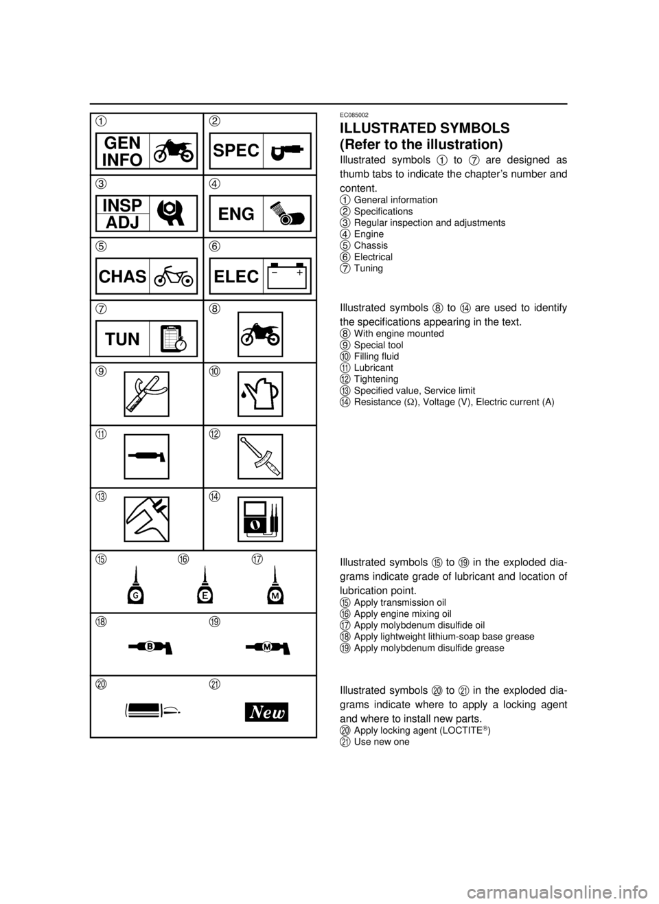
Illustrated symbols 1to 7are designed as
thumb tabs to indicate the chapter’s number and
content.
1
General information
2Specifications
3Regular inspection and adjustments
4Engine
5Chassis
6Electrical
7Tuning
Illustrated symbols 8to rare used to identify
the specifications appearing in the text.
8
With engine mounted
9Special tool
0Filling fluid
qLubricant
wTightening
eSpecified value, Service limit
rResistance (½), Voltage (V), Electric current (A)
Illustrated symbols tto oin the exploded dia-
grams indicate grade of lubricant and location of
lubrication point.
t
Apply transmission oil
yApply engine mixing oil
uApply molybdenum disulfide oil
iApply lightweight lithium-soap base grease
oApply molybdenum disulfide grease
Illustrated symbols pto ain the exploded dia-
grams indicate where to apply a locking agent
and where to install new parts.
p
Apply locking agent (LOCTITER)
aUse new one
GEN
INFO
12
3
5
74
6
8
90
qw
er
tyu
io
pa
SPEC
INSP
ADJENG
CHASELEC
TUN
5MV-9-30-0 6/19/00 2:05 PM Page 14
Page 18 of 558
EC090010
INDEX
GENERAL
INFORMATION
SPECIFICATIONS
REGULAR
INSPECTION AND
ADJUSTMENTS
ENGINE
CHASSIS
ELECTRICAL
TUNING
5MV-9-30-0 6/19/00 2:05 PM Page 16
Page 20 of 558

EC0A0000
CONTENTS
CHAPTER 1
GENERAL INFORMATION
DESCRIPTION............................................1-1
MACHINE IDENTIFICATION......................1-2
IMPORTANT INFORMATION.....................1-3
CHECKING OF CONNECTION..................1-6
SPECIAL TOOLS........................................1-7
CONTROL FUNCTIONS.............................1-9
FUEL AND ENGINE MIXING OIL.............1-12
STARTING AND BREAK-IN.....................1-13
TORQUE-CHECK POINTS.......................1-16
CLEANING AND STORAGE....................1-17
CHAPTER 2
SPECIFICATIONS
GENERAL SPECIFICATIONS....................2-1
MAINTENANCE SPECIFICATIONS...........2-3
GENERAL TORQUE SPECIFICATIONS..2-12
DEFINITION OF UNITS............................2-12
CABLE ROUTING DIAGRAM..................2-13
CHAPTER 3
REGULAR INSPECTION
AND ADJUSTMENTS
MAINTENANCE INTERVALS.....................3-1
PRE-OPERATION INSPECTION AND
MAINTENANCE..........................................3-4
ENGINE.......................................................3-5
CHASSIS...................................................3-17
ELECTRICAL............................................3-38
5MV-9-30-0 6/19/00 2:05 PM Page 18
Page 22 of 558

CHAPTER 4
ENGINE
SEAT, FUEL TANK AND SIDE
COVERS.....................................................4-1
EXHAUST PIPE AND SILENCER..............4-3
RADIATOR..................................................4-4
CARBURETOR AND REED VALVE...........4-7
CYLINDER HEAD , CYLINDER AND
PISTON.....................................................4-17
CLUTCH AND PRIMARY DRIVEN
GEAR.......................................................4-30
KICK AXLE, SHIFT SHAFT AND
PRIMARY DRIVE GEAR...........................4-38
YPVS GOVERNOR...................................4-46
WATER PUMP..........................................4-49
CDI MAGNETO.........................................4-53
ENGINE REMOVAL..................................4-57
CRANKCASE AND CRANKSHAFT.........4-62
TRANSMISSION, SHIFT CAM AND
SHIFT FORK.............................................4-69
CHAPTER 5
CAHSSIS
FRONT WHEEL AND REAR WHEEL........5-1
FRONT BRAKE AND REAR BRAKE.......5-10
FRONT FORK...........................................5-27
HANDLEBAR............................................5-40
STEERING................................................5-47
SWINGARM..............................................5-52
REAR SHOCK ABSORBER.....................5-59
5MV-9-30-0 6/19/00 2:05 PM Page 20
Page 24 of 558
CHAPTER 6
ELECTRICAL
ELECTRICAL COMPONENTS AND
WIRING DIAGRAM.....................................6-1
IGNITION SYSTEM.....................................6-2
CHAPTER 7
TUNING
ENGINE.......................................................7-1
CHASSIS...................................................7-13
5MV-9-30-0 6/19/00 2:05 PM Page 22