Page 107 of 132

PERIODIC MAINTENANCE AND MINOR REPAIR
7-34
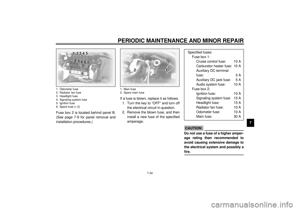
7 Fuse box 2 is located behind panel B.
(See page 7-9 for panel removal and
installation procedures.)If a fuse is blown, replace it as follows.
1. Turn the key to “OFF” and turn off
the electrical circuit in question.
2. Remove the blown fuse, and then
install a new fuse of the specified
amperage.
EC000103
CAUTION:@ Do not use a fuse of a higher amper-
age rating than recommended to
avoid causing extensive damage to
the electrical system and possibly a
fire. @
1. Odometer fuse
2. Radiator fan fuse
3. Headlight fuse
4. Signaling system fuse
5. Ignition fuse
6. Spare fuse (´ 2)
1. Main fuse
2. Spare main fuse
Specified fuses:
Fuse box 1:
Cruise control fuse: 10 A
Carburetor heater fuse: 10 A
Auxiliary DC terminal
fuse: 5 A
Auxiliary DC jack fuse: 5 A
Audio system fuse: 10 A
Fuse box 2:
Ignition fuse: 10 A
Signaling system fuse: 15 A
Headlight fuse: 15 A
Radiator fan fuse: 10 A
Odometer fuse: 10 A
Main fuse: 30 A
E_5jc.book Page 34 Monday, January 22, 2001 12:12 PM
Page 123 of 132

SPECIFICATIONS
9-4
9
Bulb voltage, wattage ´ quantity
Headlight 12 V, 60/55 W ´ 1
Tail/brake light 12 V, 5/21 W ´ 1
Turn signal light 12 V, 21 W ´ 4
Auxiliary light 12 V, 4 W ´ 1
License light 12 V, 5 W ´ 2
Neutral indicator light 12 V, 1.7 W ´ 1
High beam indicator light 12 V, 1.7 W ´ 1
Oil level warning light 12 V, 1.7 W ´ 1
Turn signal indicator light 12 V, 1.7 W ´ 2
Fuel level warning light 14 V, 3 W ´ 1
Coolant temperature warning
light 12 V, 1.7 W ´ 1
Engine trouble warning light 12 V, 1.7 W ´ 1
Overdrive indicator light 12 V, 1.7 W ´ 1
Cruise control “SET” indicator
light 12 V, 1.7 W ´ 1
Cruise control “RES” indicator
light 12 V, 1.7 W ´ 1
Cruise control “ON” indicator
light 12 V, 1.7 W ´ 1Audio system amplifier
Output power
Speaker 14 W ´ 4
Headset 1 W ´ 2
Auto-volume range 5 steps
Output impedance
Speaker 4 W
Headset 8–16 W
Fuses
Main fuse 30 A
Headlight fuse 15 A
Signaling system fuse 15 A
Ignition fuse 10 A
Radiator fan fuse 10 A
Odometer fuse 10 A
Cruise control fuse 10 A
Carburetor heater fuse 10 A
Audio system fuse 10 A
Auxiliary DC jack fuse 5 A
Auxiliary DC terminal fuse 5 A
E_5jc.book Page 4 Monday, January 22, 2001 12:12 PM
Page 128 of 132

11-INDEXAAir filter elements, cleaning .................... 7-17
Anti-theft alarm ........................................3-8
Audio settings (basic) ...............................4-5
Audio settings (modes) ............................4-5
Audio system parts, location of................4-1
Auxiliary audio source ............................ 4-18
Auxiliary DC jack and terminals.............. 3-24BBattery ................................................... 7-32
Brake and clutch fluid levels,
checking .............................................. 7-28
Brake and clutch fluids, changing........... 7-29
Brake and clutch levers, checking and
lubricating ............................................ 7-30
Brake and shift pedals, checking and
lubricating ............................................ 7-29
Brake lever............................................. 3-11
Brake lever free play, adjusting .............. 7-25
Brake light switch (rear), adjusting ......... 7-26
Brake pads, checking............................. 7-27
Brake pedal............................................ 3-11
Brake pedal position, adjusting .............. 7-26CCarburetors, adjusting............................ 7-19
Care.........................................................8-1
Cassette deck operation ..........................4-9
CD changer operation ............................ 4-17
Clutch lever ............................................ 3-10
Clutch lever free play ............................. 7-25
Conversion table ......................................9-5
Coolant level, checking .......................... 7-15
Coolant temperature warning light ........... 3-4
Cowlings and panels, removing and
installing................................................ 7-6
Cruise control indicator lights ................... 3-4
Cruise control switches .......................... 3-10
Cruise control system .............................. 3-6DDimmer switch ......................................... 3-9EEngine break-in ....................................... 6-5
Engine oil and oil filter cartridge ............. 7-12
Engine stop switch................................... 3-9
Engine trouble warning light .................... 3-3FFinal gear oil .......................................... 7-15
Front fork, adjusting ............................... 3-19
Front fork, checking ............................... 7-31
Fuel ....................................................... 3-12
Fuel cock ............................................... 3-13
Fuel consumption, tips for reducing ......... 6-4
Fuel gauge .............................................. 3-8
Fuel level warning light ............................ 3-4
Fuel tank breather hose ......................... 3-13
Fuel tank cap ......................................... 3-11
Fuses, replacing .................................... 7-33HHandlebar switches ................................. 3-9
Headlight bulb, replacing ....................... 7-35
Headsets ................................................. 4-2
Helmet holders ...................................... 3-15
High beam indicator light ......................... 3-3
Horn switch ..............................................3-9IIdentification numbers ............................10-1
Idling speed, adjusting ...........................7-20
Ignition circuit cut-off system ..................3-22
Indicator and warning lights......................3-3KKey identification number .......................10-1LLicense plate light bulb, replacing...........7-37
Light switch ..............................................3-9MMain switch/steering lock .........................3-1
Model label ............................................10-2NNeutral indicator light ...............................3-4OOil level warning light ...............................3-3
Overdrive indicator light............................3-3PParking.....................................................6-6
Part locations ...........................................2-1
Pass switch ..............................................3-9
Periodic maintenance and lubrication
chart ......................................................7-3
Pre-operation check list ............................5-1RRadio operation......................................4-12
Rider seat ..............................................3-15
E_5jc.book Page 1 Monday, January 22, 2001 12:12 PM