2001 YAMAHA XVS250 wheel
[x] Cancel search: wheelPage 7 of 88

EAU00009
TABLE OF CONTENTS
GIVE SAFETY THE RIGHT OF WAY .................1-1
DESCRIPTION ...................................................2-1
Left view ............................................................. 2-1
Right view...........................................................2-2
Controls and instruments ................................... 2-3
INSTRUMENT AND CONTROL FUNCTIONS ....3-1
Main switch/steering lock ..................................3-1
Indicator and warning lights ..............................3-2
Speedometer unit ..............................................3-3
Self-diagnosis device ........................................3-3
Anti-theft alarm (optional) ..................................3-3
Handlebar switches ...........................................3-4
Clutch lever .......................................................3-5
Shift pedal .........................................................3-5
Brake lever ........................................................3-6
Brake pedal .......................................................3-6
Fuel tank cap .....................................................3-6
Fuel ...................................................................3-7
Fuel cock ...........................................................3-8
Starter (choke) lever ..........................................3-9
Helmet holder ....................................................3-9
Adjusting the shock absorber assemblies ....... 3-10
Sidestand ........................................................ 3-11
Ignition circuit cut-off system ........................... 3-11PRE-OPERATION CHECKS ...............................4-1
Pre-operation check list .....................................4-1
OPERATION AND IMPORTANT RIDING
POINTS................................................................5-1
Starting the engine ............................................5-1
Starting a warm engine .....................................5-2
Shifting ..............................................................5-3
Recommended shift points
(for Switzerland only) .....................................5-3
Tips for reducing fuel consumption ...................5-4
Engine break-in .................................................5-4
Parking ..............................................................5-5
PERIODIC MAINTENANCE AND MINOR
REPAIR................................................................6-1
Owner’s tool kit ..................................................6-1
Periodic maintenance and lubrication chart ......6-2
Removing and installing panels ........................6-5
Checking the spark plugs ..................................6-8
Engine oil and oil filter element .......................6-10
Cleaning the air filter element .........................6-12
Adjusting the carburetor ..................................6-14
Adjusting the engine idling speed ...................6-15
Adjusting the throttle cable free play ...............6-15
Adjusting the valve clearance .........................6-16
Tires ................................................................6-16
Spoke wheels ..................................................6-19
123
456
E_5kr.book Page 1 Tuesday, September 12, 2000 4:46 PM
Page 8 of 88

TABLE OF CONTENTS
Adjusting the clutch lever free play ................. 6-19
Adjusting the brake lever free play .................. 6-20
Adjusting the brake pedal position and
free play ....................................................... 6-20
Adjusting the rear brake light switch ............... 6-22
Checking the front brake pads and
rear brake shoes ......................................... 6-22
Checking the brake fluid level ......................... 6-23
Changing the brake fluid ................................. 6-24
Drive chain slack ............................................. 6-24
Lubricating the drive chain .............................. 6-26
Checking and lubricating the cables ............... 6-27
Checking and lubricating the brake and
shift pedals .................................................. 6-27
Checking and lubricating the brake and
clutch levers ................................................ 6-28
Checking and lubricating the sidestand .......... 6-28
Checking the front fork .................................... 6-28
Checking the steering ..................................... 6-29
Checking the wheel bearings .......................... 6-30
Battery ............................................................. 6-30
Replacing the fuses ........................................ 6-32
Replacing the headlight bulb ........................... 6-33
Replacing the tail/brake light bulb ................... 6-35
Replacing a turn signal light bulb .................... 6-36
Supporting the motorcycle .............................. 6-36
Front wheel ..................................................... 6-37
Rear wheel ...................................................... 6-39Troubleshooting .............................................. 6-40
Troubleshooting chart ..................................... 6-41
MOTORCYCLE CARE AND STORAGE ............. 7-1
Care .................................................................. 7-1
Storage ............................................................. 7-4
SPECIFICATIONS ............................................... 8-1
Specifications .................................................... 8-1
Conversion table ............................................... 8-5
CONSUMER INFORMATION.............................. 9-1
Identification numbers ....................................... 9-1
Key identification number .................................. 9-1
Vehicle identification number ............................ 9-1
Model label ........................................................ 9-2
789
E_5kr.book Page 2 Tuesday, September 12, 2000 4:46 PM
Page 26 of 88

PRE-OPERATION CHECKS
4-2
4
Control cables• Make sure that operation is smooth.
• Lubricate if necessary.6-27
Drive chain• Check chain slack.
• Adjust if necessary.
• Check chain condition.
• Lubricate if necessary.6-24–6-25
Wheels and tires• Check for damage.
• Check tire condition and tread depth.
• Check air pressure.
• Correct if necessary.6-16–6-19
Brake and shift pedals• Make sure that operation is smooth.
• Lubricate pedal pivoting points if necessary.6-27
Brake and clutch levers• Make sure that operation is smooth.
• Lubricate lever pivoting points if necessary.6-28
Sidestand• Make sure that operation is smooth.
• Lubricate pivot if necessary.6-28
Chassis fasteners• Make sure that all nuts, bolts and screws are properly tightened.
• Tighten if necessary.—
Instruments, lights, signals
and switches• Check operation.
• Correct if necessary.—
Sidestand switch• Check operation of ignition circuit cut-off system.
• If system is defective, have Yamaha dealer check vehicle.3-11 ITEM CHECKS PAGE
E_5kr.book Page 2 Tuesday, September 12, 2000 4:46 PM
Page 35 of 88

PERIODIC MAINTENANCE AND MINOR REPAIR
6-3
6
10
*Wheels• Check runout, spoke tightness and for damage.
• Tighten spokes if necessary.ÖÖÖÖ
11*Tires• Check tread depth and for damage.
• Replace if necessary.
• Check air pressure.
• Correct if necessary.ÖÖÖÖ
12*Wheel bearings• Check bearing for looseness or damage.ÖÖÖÖ
13*Swingarm• Check operation and for excessive play.ÖÖÖÖ
• Lubricate with molybdenum disulfide grease. Every 50,000 km
14 Drive chain• Check chain slack.
• Make sure that the rear wheel is properly aligned.
• Clean and lubricate.Every 1,000 km and after washing
the motorcycle or riding in the rain.
15*Steering bearings• Check bearing play and steering for roughness.ÖÖÖÖÖ
• Lubricate with lithium-soap-based grease. Every 20,000 km
16*Chassis fasteners• Make sure that all nuts, bolts and screws are properly tightened.ÖÖÖÖ Ö
17 Sidestand• Check operation.
• Lubricate.ÖÖÖÖ Ö
18*Sidestand switch• Check operation.ÖÖÖÖÖ Ö
19*Front fork• Check operation and for oil leakage.ÖÖÖÖ
20*Rear shock absorber
assemblies• Check operation and shock absorbers for oil leakage.ÖÖÖÖ
21*Carburetor• Check starter (choke) operation.
• Adjust engine idling speed.ÖÖÖÖÖ Ö
22 Engine oil• Change.ÖÖÖÖÖ Ö
23 Engine oil filter element• Replace.ÖÖÖ
24*Front and rear brake
switches• Check operation.ÖÖÖÖÖ Ö
25 Moving parts and cables• Lubricate.ÖÖÖÖ Ö NO. ITEM CHECK OR MAINTENANCE JOBODOMETER READING (´1,000 km)
ANNUAL
CHECK
1 10203040
E_5kr.book Page 3 Tuesday, September 12, 2000 4:46 PM
Page 50 of 88

PERIODIC MAINTENANCE AND MINOR REPAIR
6-18
6
EW000079
WARNING
_ l
Have a Yamaha dealer replace
excessively worn tires. Besides
being illegal, operating the
motorcycle with excessively
worn tires decreases riding sta-
bility and can lead to loss of
control.
l
The replacement of all wheel-
and brake-related parts, includ-
ing the tires, should be left to a
Yamaha dealer, who has the
necessary professional knowl-
edge and experience.
_
Tire information
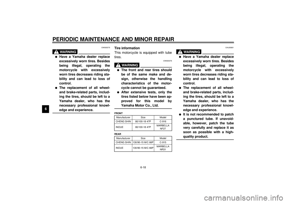
This motorcycle is equipped with tube
tires.
EW000078
WARNING
_ l
The front and rear tires should
be of the same make and de-
sign, otherwise the handling
characteristics of the motor-
cycle cannot be guaranteed.
l
After extensive tests, only the
tires listed below have been ap-
proved for this model by
Yamaha Motor Co., Ltd.
_CE-10EEAU00681
WARNING
_ l
Have a Yamaha dealer replace
excessively worn tires. Besides
being illegal, operating the
motorcycle with excessively
worn tires decreases riding sta-
bility and can lead to loss of
control.
l
The replacement of all wheel-
and brake-related parts, includ-
ing the tires, should be left to a
Yamaha dealer, who has the
necessary professional knowl-
edge and experience.
l
It is not recommended to patch
a punctured tube. If unavoid-
able, however, patch the tube
very carefully and replace it as
soon as possible with a high-
quality product.
_
FRONT
Manufacturer Size Model
CHENG SHIN 80/100-18 47P C-916
INOUE 80/100-18 47PMARBELLA
NF27
REAR
Manufacturer Size Model
CHENG SHIN 130/90-15 M/C 66P C-915
INOUE 130/90-15 M/C 66PMARBELLA
NR31
E_5kr.book Page 18 Tuesday, September 12, 2000 4:46 PM
Page 51 of 88

PERIODIC MAINTENANCE AND MINOR REPAIR
6-19
6
EAU00685
Spoke wheels To maximize the performance, durabil-
ity, and safe operation of your motor-
cycle, note the following points
regarding the specified wheels.l
The wheel rims should be checked
for cracks, bends or warpage, and
the spokes for looseness or dam-
age before each ride. If any dam-
age is found, have a Yamaha
dealer replace the wheel. Do not
attempt even the smallest repair to
the wheel. A deformed or cracked
wheel must be replaced.
l
The wheel should be balanced
whenever either the tire or wheel
has been changed or replaced. An
unbalanced wheel can result in
poor performance, adverse han-
dling characteristics, and a short-
ened tire life.
l
Ride at moderate speeds after
changing a tire since the tire sur-
face must first be “broken in” for it to
develop its optimal characteristics.
EAU00694
Adjusting the clutch lever free
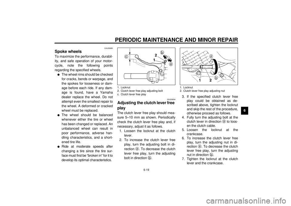
play The clutch lever free play should mea-
sure 5–10 mm as shown. Periodically
check the clutch lever free play and, if
necessary, adjust it as follows.
1. Loosen the locknut at the clutch
lever.
2. To increase the clutch lever free
play, turn the adjusting bolt in di-
rection
a. To decrease the clutch
lever free play, turn the adjusting
bolt in direction
b.3. If the specified clutch lever free
play could be obtained as de-
scribed above, tighten the locknut
and skip the rest of the procedure,
otherwise proceed as follows.
4. Fully turn the adjusting bolt at the
clutch lever in direction
a to loos-
en the clutch cable.
5. Loosen the locknut at the
crankcase.
6. To increase the clutch lever free
play, turn the adjusting nut in di-
rection
a. To decrease the clutch
lever free play, turn the adjusting
nut in direction
b.
7. Tighten the locknut at the clutch
lever and the crankcase.1. Locknut
2. Clutch lever free play adjusting bolt
c. Clutch lever free play
1. Locknut
2. Clutch lever free play adjusting nut
E_5kr.book Page 19 Tuesday, September 12, 2000 4:46 PM
Page 53 of 88

PERIODIC MAINTENANCE AND MINOR REPAIR
6-21
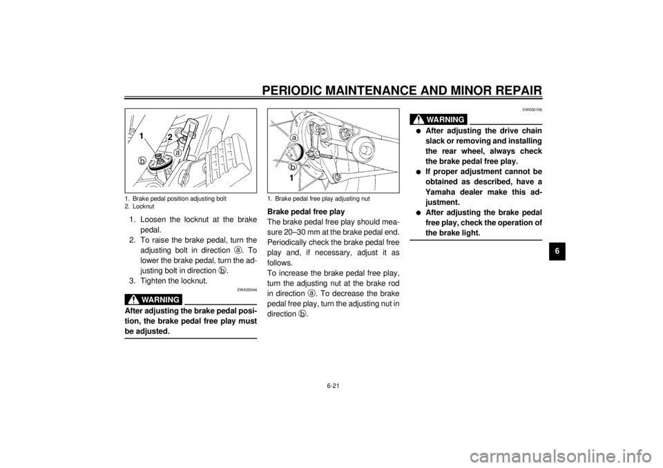
6 1. Loosen the locknut at the brake
pedal.
2. To raise the brake pedal, turn the
adjusting bolt in direction
a. To
lower the brake pedal, turn the ad-
justing bolt in direction
b.
3. Tighten the locknut.
EWA00044
WARNING
_ After adjusting the brake pedal posi-
tion, the brake pedal free play must
be adjusted. _
Brake pedal free play
The brake pedal free play should mea-
sure 20–30 mm at the brake pedal end.
Periodically check the brake pedal free
play and, if necessary, adjust it as
follows.
To increase the brake pedal free play,
turn the adjusting nut at the brake rod
in direction
a. To decrease the brake
pedal free play, turn the adjusting nut in
direction
b.
EW000106
WARNING
_ l
After adjusting the drive chain
slack or removing and installing
the rear wheel, always check
the brake pedal free play.
l
If proper adjustment cannot be
obtained as described, have a
Yamaha dealer make this ad-
justment.
l
After adjusting the brake pedal
free play, check the operation of
the brake light.
_
1. Brake pedal position adjusting bolt
2. Locknut
1. Brake pedal free play adjusting nut
E_5kr.book Page 21 Tuesday, September 12, 2000 4:46 PM
Page 57 of 88

PERIODIC MAINTENANCE AND MINOR REPAIR
6-25
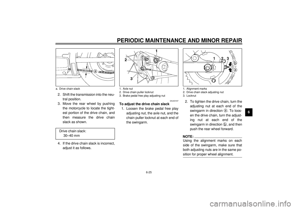
6 2. Shift the transmission into the neu-
tral position.
3. Move the rear wheel by pushing
the motorcycle to locate the tight-
est portion of the drive chain, and
then measure the drive chain
slack as shown.
4. If the drive chain slack is incorrect,
adjust it as follows.
EAU03187
To adjust the drive chain slack
1. Loosen the brake pedal free play
adjusting nut, the axle nut, and the
chain puller locknut at each end of
the swingarm.2. To tighten the drive chain, turn the
adjusting nut at each end of the
swingarm in direction
a. To loos-
en the drive chain, turn the adjust-
ing nut at each end of the
swingarm in direction
b, and then
push the rear wheel forward.
NOTE:_ Using the alignment marks on each
side of the swingarm, make sure that
both adjusting nuts are in the same po-
sition for proper wheel alignment. _
a. Drive chain slack
Drive chain slack:
30–40 mm
1. Axle nut
2. Drive chain puller locknut
3. Brake pedal free play adjusting nut
1. Alignment marks
2. Drive chain slack adjusting nut
3. Locknut
E_5kr.book Page 25 Tuesday, September 12, 2000 4:46 PM