2001 YAMAHA XVS1100A steering
[x] Cancel search: steeringPage 13 of 104

DESCRIPTION
2-2
2
Right view (XVS1100)9. Engine oil filter element (page 6-7)
10. Battery (page 6-26)
11. Main fuse (page 6-28)
12. Main switch/steering lock (page 3-1)
13. Air filter element (page 6-11)
14. Brake pedal (page 3-7)
E_5pb.book Page 2 Thursday, October 5, 2000 10:10 AM
Page 15 of 104

DESCRIPTION
2-4
2
Right view (XVS1100A)9. Engine oil filter element (page 6-7)
10. Battery (page 6-26)
11. Main fuse (page 6-28)
12. Main switch/steering lock (page 3-1)
13. Air filter element (page 6-11)
14. Brake pedal (page 3-7)
E_5pb.book Page 4 Thursday, October 5, 2000 10:10 AM
Page 17 of 104

INSTRUMENT AND CONTROL FUNCTIONS
3
Main switch/steering lock .................................................................. 3-1
Indicator and warning lights ............................................................. 3-2
Speedometer unit .............................................................................. 3-3
Anti-theft alarm (optional) .................................................................. 3-4
Handlebar switches ........................................................................... 3-4
Clutch lever ....................................................................................... 3-5
Shift pedal (XVS1100)........................................................................ 3-6
Shift pedal (XVS1100A) ..................................................................... 3-6
Brake lever ........................................................................................ 3-6
Brake pedal ....................................................................................... 3-7
Fuel tank cap ..................................................................................... 3-7
Fuel ................................................................................................... 3-8
Fuel cock ........................................................................................... 3-9
Starter (choke) lever ......................................................................... 3-10
Seats (XVS1100) ............................................................................ 3-11
Seats (XVS1100A) ........................................................................... 3-12
Helmet holder .................................................................................. 3-13
Storage compartment ..................................................................... 3-14
Adjusting the shock absorber assembly .......................................... 3-15
Luggage strap holders .................................................................... 3-18
Sidestand ........................................................................................ 3-18
Ignition circuit cut-off system ........................................................... 3-19
E_5pb.book Page 1 Thursday, October 5, 2000 10:10 AM
Page 18 of 104

3-1
3
EAU00027
3-INSTRUMENT AND CONTROL FUNCTIONS
EAU00029
Main switch/steering lock The main switch/steering lock controls
the ignition and lighting systems, and is
used to lock the steering. The various
positions are described below.
EAU00036
ON
All electrical systems are supplied with
power, and the engine can be started.
The key cannot be removed.
EAU00038
OFF
All electrical systems are off. The key
can be removed.
EAU00040
LOCK
The steering is locked, and all electrical
systems are off. The key can be re-
moved.
To lock the steering1. Turn the handlebars all the way to
the left.
2. Push the key in from the “OFF” po-
sition, and then turn it to “LOCK”
while still pushing it.
3. Remove the key.
To unlock the steeringPush the key in, and then turn it to
“OFF” while still pushing it.
EW000016
WARNING
@ Never turn the key to “OFF” or
“LOCK” while the motorcycle is
moving, otherwise the electrical
systems will be switched off, which
may result in loss of control or an
accident. Make sure that the motor-
cycle is stopped before turning the
key to “OFF” or “LOCK”. @1. Push.
2. Turn.
E_5pb.book Page 1 Thursday, October 5, 2000 10:10 AM
Page 19 of 104

INSTRUMENT AND CONTROL FUNCTIONS
3-2
3
EAU01590
(Parking)
The steering is locked, and the taillight
and auxiliary light are on, but all other
electrical systems are off. The key can
be removed.
The steering must be locked before the
key can be turned to “ ”.
ECA00043
CAUTION:@ Do not use the parking position for
an extended length of time, other-
wise the battery may discharge. @
EAU03034
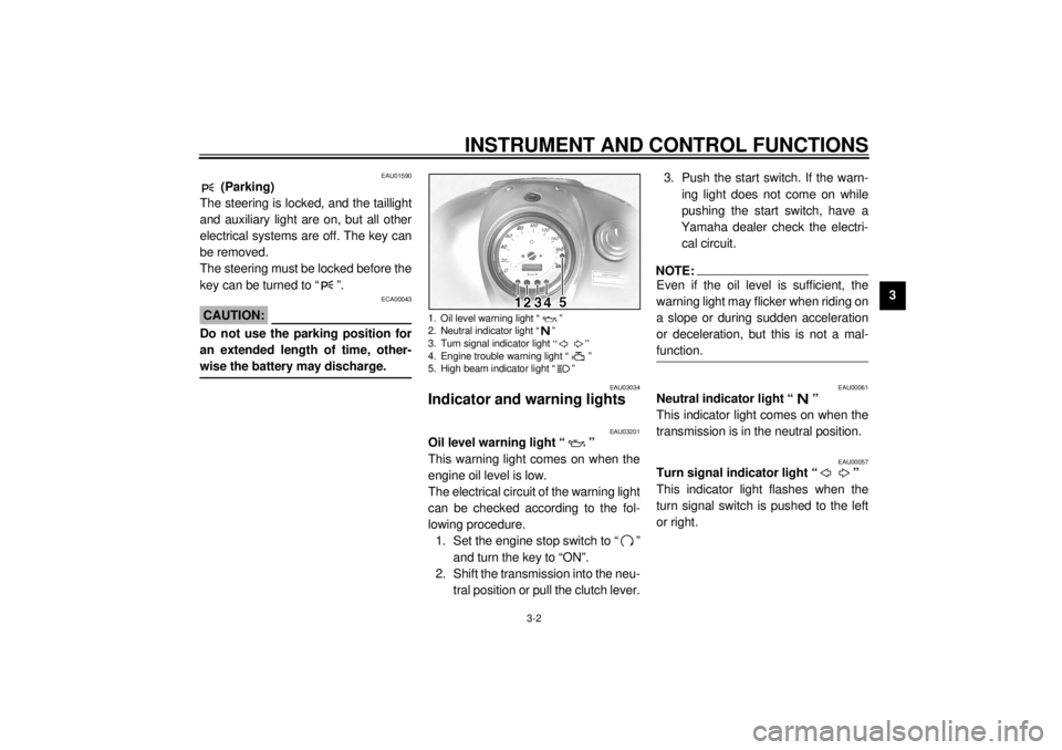
Indicator and warning lights
EAU03201
Oil level warning light “ ”
This warning light comes on when the
engine oil level is low.
The electrical circuit of the warning light
can be checked according to the fol-
lowing procedure.
1. Set the engine stop switch to “ ”
and turn the key to “ON”.
2. Shift the transmission into the neu-
tral position or pull the clutch lever.3. Push the start switch. If the warn-
ing light does not come on while
pushing the start switch, have a
Yamaha dealer check the electri-
cal circuit.
NOTE:@ Even if the oil level is sufficient, the
warning light may flicker when riding on
a slope or during sudden acceleration
or deceleration, but this is not a mal-
function. @
EAU00061
Neutral indicator light “ ”
This indicator light comes on when the
transmission is in the neutral position.
EAU00057
Turn signal indicator light “ ”
This indicator light flashes when the
turn signal switch is pushed to the left
or right.
1. Oil level warning light “ ”
2. Neutral indicator light “ ”
3. Turn signal indicator light “”
4. Engine trouble warning light “ ”
5. High beam indicator light “ ”
E_5pb_Functions.fm Page 2 Thursday, October 5, 2000 2:16 PM
Page 49 of 104

6
PERIODIC MAINTENANCE AND MINOR REPAIR
Owner’s tool kit .................................................... 6-1
Periodic maintenance and lubrication chart ......... 6-2
Removing and installing the panel ....................... 6-5
Checking the spark plugs .................................... 6-6
Engine oil and oil filter element ............................ 6-7
Final gear oil ........................................................ 6-9
Cleaning the air filter element ............................ 6-11
Adjusting the carburetors ................................... 6-12
Adjusting the engine idling speed ...................... 6-12
Adjusting the throttle cable free play .................. 6-13
Adjusting the valve clearance ............................ 6-13
Tires ................................................................... 6-13
Spoke wheels .................................................... 6-16
Adjusting the clutch lever free play .................... 6-17
Adjusting the brake lever free play ..................... 6-17
Adjusting the brake pedal position ..................... 6-19
Adjusting the rear brake light switch .................. 6-19
Checking the front and rear brake pads ............. 6-20
Checking the brake fluid level ............................ 6-21Changing the brake fluid ................................... 6-22
Checking and lubricating the cables ................. 6-22
Checking and lubricating the throttle grip
and cable ........................................................ 6-22
Checking and lubricating the brake and
shift pedals ...................................................... 6-23
Checking and lubricating the brake and
clutch levers .................................................... 6-23
Checking and lubricating the sidestand ............ 6-24
Checking the front fork ...................................... 6-24
Checking the steering ....................................... 6-25
Checking the wheel bearings ............................ 6-25
Battery ............................................................... 6-26
Replacing the fuses .......................................... 6-28
Replacing the headlight bulb ............................. 6-30
Replacing a turn signal light bulb or
the tail/brake light bulb .................................... 6-31
Troubleshooting ................................................. 6-32
Troubleshooting chart ........................................ 6-33
E_5pb.book Page 1 Thursday, October 5, 2000 10:10 AM
Page 52 of 104

PERIODIC MAINTENANCE AND MINOR REPAIR
6-3
6
9
*Brake hoses• Check for cracks or damage.ÖÖÖÖ Ö
• Replace. (See NOTE on page 6-4.) Every 4 years
10*Wheels• Check runout, spoke tightness and for damage.
• Tighten spokes if necessary.ÖÖÖÖ
11*Tires• Check tread depth and for damage.
• Replace if necessary.
• Check air pressure.
• Correct if necessary.ÖÖÖÖ
12*Wheel bearings• Check bearing for looseness or damage.ÖÖÖÖ
13*Swingarm• Check operation and for excessive play.ÖÖÖÖ
• Lubricate with molybdenum disulfide grease. Every 50,000 km
14*Steering bearings• Check bearing play and steering for roughness.ÖÖÖÖÖ
• Lubricate with lithium-soap-based grease. Every 20,000 km
15*Chassis fasteners• Make sure that all nuts, bolts and screws are properly tightened.ÖÖÖÖ Ö
16 Sidestand• Check operation.
• Lubricate.ÖÖÖÖ Ö
17*Sidestand switch• Check operation.ÖÖÖÖÖ Ö
18*Front fork• Check operation and for oil leakage.ÖÖÖÖ
19*Rear shock absorber
assembly• Check operation and shock absorber for oil leakage.ÖÖÖÖ
• Lubricate the pivoting points with molybdenum disulfide
grease.ÖÖ
20*Carburetors• Check starter (choke) operation.
• Adjust engine idling speed and synchronization.ÖÖÖÖÖ Ö
21 Engine oil• Change.ÖÖÖÖÖ Ö
22 Engine oil filter element•Replace.ÖÖÖ NO. ITEM CHECK OR MAINTENANCE JOBODOMETER READING (´ 1,000 km)
ANNUAL
CHECK
1 10203040
E_5pb_Periodic.fm Page 3 Thursday, December 14, 2000 4:31 PM
Page 74 of 104

PERIODIC MAINTENANCE AND MINOR REPAIR
6-25
6
EAU00794
Checking the steering Worn or loose steering bearings may
cause danger. Therefore, the operation
of the steering must be checked as fol-
lows at the intervals specified in the pe-
riodic maintenance and lubrication
chart.
1. Place a stand under the engine to
raise the front wheel off the
ground.
EW000115
WARNING
@ Securely support the motorcycle so
that there is no danger of it falling
over. @
2. Hold the lower ends of the front
fork legs and try to move them for-
ward and backward. If any free
play can be felt, have a Yamaha
dealer check or repair the steer-
ing.
EAU01144
Checking the wheel bearings The front and rear wheel bearings must
be checked at the intervals specified in
the periodic maintenance and lubrica-
tion chart. If there is play in the wheel
hub or if the wheel does not turn
smoothly, have a Yamaha dealer
check the wheel bearings.
E_5pb.book Page 25 Thursday, October 5, 2000 10:10 AM