Page 17 of 100

INSTRUMENT AND CONTROL FUNCTIONS
3-2
3
EAU01590
(Parking)
The steering is locked, and the taillight
and auxiliary light are on, but all other
electrical systems are off. The key can
be removed.
The steering must be locked before the
key can be turned to “ ”.
ECA00043
CAUTION:@ Do not use the parking position for
an extended length of time, other-
wise the battery may discharge. @
EAU03034
Indicator and warning lights
EAU03299
Turn signal indicator lights
“” / “”
The corresponding indicator light flash-
es when the turn signal switch is
pushed to the left or right.
EAU03680
Fuel level warning light “ ”
This warning light comes on when the
fuel level drops below approximately
5 L. When this occurs, refuel as soon
as possible.
The electrical circuit of the warning light
can be checked according to the fol-
lowing procedure.
1. Set the engine stop switch to “ ”
and turn the key to “ON”.
2. Shift the transmission into the neu-
tral position or pull the clutch lever.
3. Push the start switch. If the warn-
ing light does not come on, have a
Yamaha dealer check the electri-
cal circuit.
1. Left turn signal indicator light “ ”
2. Fuel level warning light “ ”
3. Neutral indicator light “ ”
4. High beam indicator light “ ”
5. Oil level warning light “ ”
6. Right turn signal indicator light “ ”
E_4km.book Page 2 Thursday, September 7, 2000 9:32 AM
Page 18 of 100

INSTRUMENT AND CONTROL FUNCTIONS
3-3
3
EAU00061
Neutral indicator light “ ”
This indicator light comes on when the
transmission is in the neutral position.
EAU00063
High beam indicator light “ ”
This indicator light comes on when the
high beam of the headlight is switched
on.
EAU03201
Oil level warning light “ ”
This warning light comes on when the
engine oil level is low.
The electrical circuit of the warning light
can be checked according to the fol-
lowing procedure.
1. Set the engine stop switch to “ ”
and turn the key to “ON”.
2. Shift the transmission into the neu-
tral position or pull the clutch lever.
3. Push the start switch. If the warn-
ing light does not come on while
pushing the start switch, have a
Yamaha dealer check the electri-
cal circuit.NOTE:@ Even if the oil level is sufficient, the
warning light may flicker when riding on
a slope or during sudden acceleration
or deceleration, but this is not a mal-
function. @
EAU00094
Speedometer unit The speedometer unit is equipped with
a speedometer, an odometer and a
tripmeter. The speedometer shows
riding speed. The odometer shows the
total distance traveled. The tripmeter
shows the distance traveled since it
was last set to zero with the reset but-
ton. The tripmeter can be used to esti-
mate the distance that can be traveled
with a full tank of fuel. This information
will enable you to plan future fuel stops.
1. Left turn signal indicator light “ ”
2. Fuel level warning light “ ”
3. Neutral indicator light “ ”
4. High beam indicator light “ ”
5. Oil level warning light “ ”
6. Right turn signal indicator light “ ”
1. Tripmeter
2. Odometer
3. Tripmeter reset button
E_4km.book Page 3 Thursday, September 7, 2000 9:32 AM
Page 21 of 100
INSTRUMENT AND CONTROL FUNCTIONS
3-6
3
EAU00118
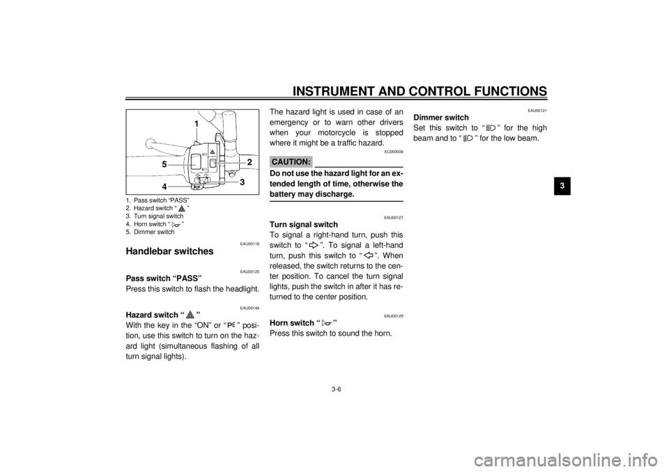
Handlebar switches
EAU00120
Pass switch “PASS”
Press this switch to flash the headlight.
EAU00144
Hazard switch “ ”
With the key in the “ON” or “ ” posi-
tion, use this switch to turn on the haz-
ard light (simultaneous flashing of all
turn signal lights).The hazard light is used in case of an
emergency or to warn other drivers
when your motorcycle is stopped
where it might be a traffic hazard.
EC000006
CAUTION:@ Do not use the hazard light for an ex-
tended length of time, otherwise the
battery may discharge. @
EAU00127
Turn signal switch
To signal a right-hand turn, push this
switch to “ ”. To signal a left-hand
turn, push this switch to “ ”. When
released, the switch returns to the cen-
ter position. To cancel the turn signal
lights, push the switch in after it has re-
turned to the center position.
EAU00129
Horn switch “ ”
Press this switch to sound the horn.
EAU00121
Dimmer switch
Set this switch to “ ” for the high
beam and to “ ” for the low beam.
1. Pass switch “PASS”
2. Hazard switch “ ”
3. Turn signal switch
4. Horn switch “ ”
5. Dimmer switch
E_4km.book Page 6 Thursday, September 7, 2000 9:32 AM
Page 72 of 100

PERIODIC MAINTENANCE AND MINOR REPAIR
6-29
6
EAU01110
Replacing the fuses The fuse boxes are located behind
cowling B. (See page 6-6 for cowling
removal and installation procedures.)
If a fuse is blown, replace it as follows.
1. Turn the key to “OFF” and turn off
the electrical circuit in question.
2. Remove the blown fuse, and then
install a new fuse of the specified
amperage.
EC000103
CAUTION:@ Do not use a fuse of a higher amper-
age rating than recommended to
avoid causing extensive damage to
the electrical system and possibly a
fire. @3. Turn the key to “ON” and turn on
the electrical circuit in question to
check if the device operates.
4. If the fuse immediately blows
again, have a Yamaha dealer
check the electrical system.
1. Fuse box (´ 2)
1. Headlight fuse
2. Ignition fuse
3. Clock fuse
4. Hazard fuse
5. Main fuse
6. Spare fuse (´ 3)
7. Signaling system fuse
Specified fuses:
Main fuse: 30 A
Headlight fuse: 15 A
Signaling system fuse: 20 A
Ignition fuse: 10 A
Clock fuse: 10 A
Hazard fuse: 10 A
E_4km.book Page 29 Thursday, September 7, 2000 9:32 AM
Page 91 of 100
SPECIFICATIONS
8-4
8
Headlight typeQuar tz bulb (halogen)
Bulb voltage, wattage ´ quantity
Headlight 12 V, 60/55 W ´ 1
Tail/brake light 12 V, 5/21 W ´ 1
Auxiliary light 12 V, 4 W ´ 1
Turn signal light 12 V, 21 W ´ 4
Meter lighting 12 V, 3.4 W ´ 4
Neutral indicator light 12 V, 3.4 W ´ 1
High beam indicator light 12 V, 3.4 W ´ 1
Oil level warning light 12 V, 3.4 W ´ 1
Turn signal indicator light 12 V, 3.4 W ´ 2
Fuel level warning light 12 V, 3.4 W ´ 1
Fuses
Main fuse 30 A
Signaling system fuse 20 A
Headlight fuse 15 A
Hazard fuse 10 A
Ignition fuse 10 A
Clock fuse 10 A
E_4km.book Page 4 Thursday, September 7, 2000 9:32 AM
Page 97 of 100

INDEX
Starting a warm engine ............................ 5-3
Start switch .............................................. 3-7
Steering, checking ................................. 6-26
Storage.................................................... 7-4
Storage compartment ............................ 3-12TTachometer ............................................. 3-4
Throttle cable free play, adjusting .......... 6-16
Throttle grip and cable, checking and
lubricating............................................ 6-23
Tires ...................................................... 6-17
Tool kit..................................................... 6-1
Troubleshooting..................................... 6-35
Troubleshooting chart ............................ 6-36
Turn signal indicator lights ....................... 3-2
Turn signal switch .................................... 3-6VValve clearance, adjusting ..................... 6-17
Vehicle identification number ................... 9-1WWheel bearings, checking...................... 6-27
Wheel (front).......................................... 6-31
Installing........................................... 6-32
Removing......................................... 6-31
Wheel (rear) .......................................... 6-33
Installing........................................... 6-34
Removing......................................... 6-33
Wheels .................................................. 6-20
E_4km.book Page 2 Thursday, September 7, 2000 9:32 AM
