2001 YAMAHA MAJESTY 250 stop start
[x] Cancel search: stop startPage 17 of 106

3-1
IGNITION
P
LOCK
ON
OFF
OPENPUSHPUSH
EAU00029
Main switch/steering lockThe main switch/steering lock con-
trols the ignition and lighting systems,
and is used to lock the steering. The
various positions are described
below.
EAU00036
ON
All electrical systems are supplied
with power, and the engine can be
started. The key cannot be removed.
EAU00038
OFF
All electrical systems are off. The key
can be removed.
EAU00040
LOCK
The steering is locked, and all electri-
cal systems are off. The key can be
removed.
To lock the steering1.Turn the handlebars all the way
to the left.
2.Push the key in from the ÒOFFÓ
position, and then turn it to
ÒLOCKÓ while still pushing it.
3.Remove the key.
To unlock the steeringPush the key in, and then turn it to
ÒOFFÓ while still pushing it.
EW000016
wNever turn the key to ÒOFFÓ or
ÒLOCKÓ while the scooter is mov-
ing, otherwise the electrical sys-
tems will be switched off, which
may result in loss of control or an
accident. Make sure that the scoot-
er is stopped before turning the
key to ÒOFFÓ or ÒLOCKÓ.
EAU03733
.
(Parking)
The steering is locked, and the tail-
light, license light and auxiliary light
are on, but all other electrical sys-
tems are off. The key can be
removed.
To turn the main switch to Ò
.
Ó
:
1.Turn the key to ÒLOCKÓ.
2.Slightly turn the key counter-
clockwise until it stops.
3.While still turning the key coun-
terclockwise, push it in until it
snaps into place.
ECA00043
cCDo not use the parking position for
an extended length of time, other-
wise the battery may discharge.
EAU00027
INSTRUMENT AND CONTROL FUNCTIONS
1
23
4
5
6
7
8
95GM-9-E1(No ABS) 9/27/00 2:18 PM Page 16
Page 22 of 106

3-6
INSTRUMENT AND CONTROL FUNCTIONS
1
23
4
5
6
7
8
9
1
2
3
EAU01871
Light switch
Set this switch to Ò
'
Ó to turn on
the auxiliary light, meter lighting, tail-
light and license plate light. Set the
switch to Ò:Ó to turn on the headlight
also.
1.Engine stop switch
2.Light switch
3.Start switch Ò,Ó
EAU00127
Turn signal switch
To signal a right-hand turn, push this
switch to Ò6Ó. To signal a left-hand
turn, push this switch to Ò4Ó. When
released, the switch returns to the
center position. To cancel the turn
signal lights, push the switch in after
it has returned to the center position.
EAU00129
Horn switch Ò*Ó
Press this switch to sound the horn.
5GM-9-E1(No ABS) 9/27/00 2:18 PM Page 21
Page 24 of 106

3-8
INSTRUMENT AND CONTROL FUNCTIONS
1
23
4
5
6
7
8
9
EAU00138
Engine stop switch
Set this switch to Ò$Ó to stop the
engine in case of an emergency,
such as when the scooter overturns
or when the throttle cable is stuck.
EAU00143
Start switch Ò,Ó
Push this switch to crank the engine
with the starter.
EC000005
cCSee page 5-1 for starting instruc-
tions prior to starting the engine.
1
2
3
1.Engine stop switch
2.Light switch
3.Start switch Ò,Ó
1
1.Front brake lever
EAU03378
Front brake leverThe front brake lever is located at the
right handlebar grip. To apply the
front brake, pull this lever toward the
handlebar grip.
1
1.Rear brake lever
EAU00163
Rear brake leverThe rear brake lever is located on the
left handlebar grip. To apply the rear
brake, pull this lever toward the han-
dlebar grip.
5GM-9-E1(No ABS) 9/27/00 2:18 PM Page 23
Page 32 of 106

3-16
INSTRUMENT AND CONTROL FUNCTIONS
1
23
4
5
6
7
8
9
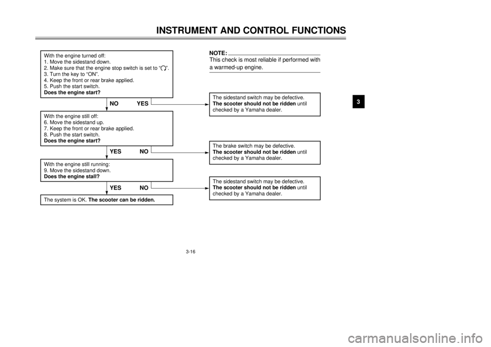
The sidestand switch may be defective.The scooter should not be ridden until
checked by a Yamaha dealer.
YES NO
With the engine turned off:
1. Move the sidestand down.
2. Make sure that the engine stop switch is set to Ò#Ó.
3. Turn the key to ÒONÓ.
4. Keep the front or rear brake applied.
5. Push the start switch.
Does the engine start?
The brake switch may be defective.
The scooter should not be ridden until
checked by a Yamaha dealer.
With the engine still off:
6. Move the sidestand up.
7. Keep the front or rear brake applied.
8. Push the start switch.
Does the engine start?With the engine still running:
9. Move the sidestand down.
Does the engine stall?
The sidestand switch may be defective.
The scooter should not be ridden until
checked by a Yamaha dealer.NOTE:This check is most reliable if performed with
a warmed-up engine.
YESNO
The system is OK.
The scooter can be ridden.
YESNO
5GM-9-E1(No ABS) 9/27/00 2:18 PM Page 31
Page 39 of 106

5-1
EAU01118
w8Become thoroughly familiar
with all operating controls and
their functions before riding.
Consult a Yamaha dealer
regarding any control or func-
tion that you do not thorough-
ly understand.
8Never start the engine or oper-
ate it in a closed area for any
length of time. Exhaust fumes
are poisonous, and inhaling
them can cause loss of con-
sciousness and death within a
short time. Always make sure
that there is adequate ventila-
tion.
8For safety, always start the
engine with the centerstand
down.
EAU03616
Starting the engine
EC000046
cCSee page 5-4 for engine break-in
instructions prior to operating the
vehicle for the first time.In order for the ignition circuit cut-off
system to enable starting, the side-
stand must be up.
EW000054
w8Before starting the engine,
check the function of the igni-
tion circuit cut-off system
according to the procedure
described on page 3-16.
8Never ride with the sidestand
down.
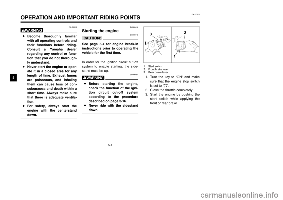
1.Turn the key to ÒONÓ and make
sure that the engine stop switch
is set to Ò#Ó.
2.Close the throttle completely.
3.Start the engine by pushing the
start switch while applying the
front or rear brake.
EAU00372
OPERATION AND IMPORTANT RIDING POINTS
1
2
3
45
6
7
8
9
32
1
1.Start switch
2.Front brake lever
3.Rear brake lever
5GM-9-E1(No ABS) 9/27/00 2:18 PM Page 38
Page 61 of 106

6-17
PERIODIC MAINTENANCE AND MINOR REPAIR
1
2
3
4
56
7
8
9
1
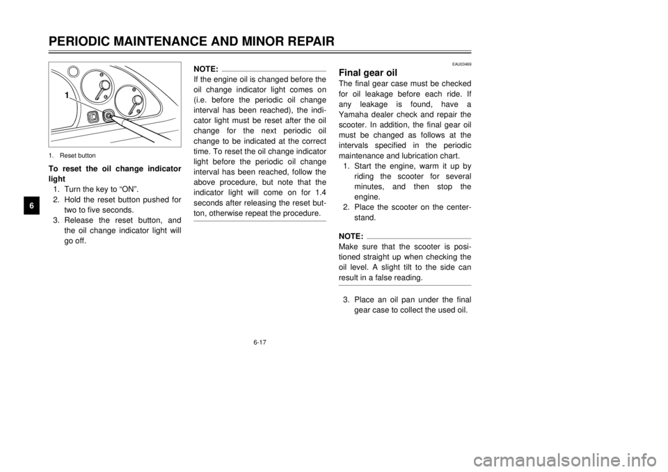
To reset the oil change indicator
light
1.Turn the key to ÒONÓ.
2.Hold the reset button pushed for
two to five seconds.
3.Release the reset button, and
the oil change indicator light will
go off.1.Reset button
NOTE:
If the engine oil is changed before the
oil change indicator light comes on
(i.e. before the periodic oil change
interval has been reached), the indi-
cator light must be reset after the oil
change for the next periodic oil
change to be indicated at the correct
time. To reset the oil change indicator
light before the periodic oil change
interval has been reached, follow the
above procedure, but note that the
indicator light will come on for 1.4
seconds after releasing the reset but-
ton, otherwise repeat the procedure.
EAU03469
Final gear oilThe final gear case must be checked
for oil leakage before each ride. If
any leakage is found, have a
Yamaha dealer check and repair the
scooter. In addition, the final gear oil
must be changed as follows at the
intervals specified in the periodic
maintenance and lubrication chart.
1.Start the engine, warm it up by
riding the scooter for several
minutes, and then stop the
engine.
2.Place the scooter on the center-
stand.NOTE:
Make sure that the scooter is posi-
tioned straight up when checking the
oil level. A slight tilt to the side can
result in a false reading.3.Place an oil pan under the final
gear case to collect the used oil.
5GM-9-E1(No ABS) 9/27/00 2:18 PM Page 60
Page 84 of 106

6-40
PERIODIC MAINTENANCE AND MINOR REPAIR
1
2
3
4
56
7
8
9 Engine overheating
EW000070
w8Do not remove the radiator cap when the engine and radiator are hot. Scalding hot fluid and steam may be
blown out under pressure, which could cause serious injury. Be sure to wait until the engine has cooled.
8After removing the radiator cap retaining bolt, place a thick rag, like a towel, over the radiator cap, and then
slowly rotate the cap counterclockwise to the detent to allow any residual pressure to escape. When the
hissing sound has stopped, press down on the cap while turning it counterclockwise, and then remove the
cap.Wait until the
engine has cooled.
Check the coolant level in the
reservoir and radiator.
The coolant level
is OK.The coolant level is low.
Check the cooling system
for leakage.
Have a Yamaha dealer checkand repair the cooling system.Add coolant. (See NOTE.)
Start the engine. If the engine overheats again,
have a
Yamaha dealer check
and repair the cooling system.
There is
leakage.
There is
no leakage.
NOTE:
If coolant is not available, tap water can be temporarily used instead, provided that it is changed to the recommended
coolant as soon as possible.
5GM-9-E1(No ABS) 9/27/00 2:18 PM Page 83
Page 101 of 106

INDEX
F
Final gear oil..........................................6-17
Front and rear brake lever free play,
adjusting.............................................6-25
Front and rear brake pads, checking.....6-26
Front fork, checking...............................6-29
Fuel.......................................................3-10
Fuel consumption, tips for reducing........5-4
Fuel gauge..............................................3-4
Fuel tank cap...........................................3-9
Fuses, replacing....................................6-33
H
Handlebar switches.................................3-5
Pass switch.........................................3-5
Dimmer switch....................................3-5
Turn signal switch...............................3-6
Horn switch.........................................3-6
Light switch.........................................3-6
Headlight variations............................3-7
Engine stop switch..............................3-8
Start switch.........................................3-8
Headlight bulb, replacing.......................6-34
I
Identification numbers.............................9-1
Ignition circuit cut-off system.................3-15
Indicator lights.........................................3-2
Oil change indicator light....................3-2
High beam indicator light....................3-2
Turn signal indicator lights..................3-2
K
Key identification number........................9-1
L
License plate light bulb, replacing.........6-37
M
Main switch/steering lock........................3-1
Model label..............................................9-2
P
Parking....................................................5-5
Part locations...........................................2-1
Periodic maintenance and lubrication
chart......................................................6-3
Pre-operation check list...........................4-1
R
Rider seat..............................................3-11
Rider seat, adjusting..............................3-12
S
Safe-riding points....................................1-2
Self-diagnosis device..............................3-3
Shock absorber assemblies, adjusting..3-14
Sidestand..............................................3-15
Spark plug, checking.............................6-12
Specifications..........................................8-1
Speedometer unit....................................3-3
Starting off...............................................5-2
Starting the engine..................................5-1
Steering, checking.................................6-30
Storage....................................................7-4
A
Acceleration and deceleration.................5-3
Air filter and V-belt case air filter
elements, cleaning..............................6-20
Air flow louver........................................6-22
Anti-theft alarm (optional)........................3-4
B
Battery...................................................6-31
Battery cover, removing........................6-31
Brake fluid level, checking.....................6-27
Brake fluid, changing.............................6-28
Brake lever (front)....................................3-8
Brake lever (rear)....................................3-8
Brake levers, lubricating........................6-28
Braking....................................................5-3
C
Cables, checking and lubricating...........6-28
Care.........................................................7-1
Catalytic converter.................................3-10
Centerstand and sidestand, checking
and lubricating....................................6-29
Clock.......................................................3-5
Conversion table.....................................8-5
Coolant..................................................6-18
Coolant temperature gauge.....................3-4
Cowlings and panel, removing and
installing................................................6-6
E
Engine break-in.......................................5-4
Engine oil...............................................6-14
5GM-9-E1(No ABS) 9/27/00 2:18 PM Page 100