xi
7Mapº switch
You can select a destination simply by
touching the location on the displayed map.
34 . . . . . . . . . . . . . . . . . . . . . . . . . . . . . . . . . . .
8Intersectionº switch
You can enter the names of two intersecting
streets. This is helpful if you do not know the
specific street address of your destination
but know the general vicinity. 35. . . . . . . . .
9Freeway Ent./Exitº switch
You can enter the name of a freeway (inter-
state) entrance or exit. 36. . . . . . . . . . . . . . .
10Phone #º switch
You can enter a destination by the telephone
number. 37. . . . . . . . . . . . . . . . . . . . . . . . . . .
11Coordinatesº switch
You can set a destination using latitude and
longitude coordinates. 37. . . . . . . . . . . . . . .
12Quick access switch
You can select one of 5 preset destinations
directly. To use this function, it is necessary
to set the Attributeº for each memory point.
(To register the Quick Accessº, see page
70.) 22. . . . . . . . . . . . . . . . . . . . . . . . . . . . . . .
13Home switch
You can select your own home without en-
tering the address each time. To use this
function, it is necessary to set the Attributeº
for the memory point. (To register the
Homeº, see page 70.) 22. . . . . . . . . . . . . .
14Changeº switch
To change the search area, touch this
switch. 20. . . . . . . . . . . . . . . . . . . . . . . . . . . .
05IOX-02
F45156
S27
F45157
GND 05-742
- DIAGNOSTICSTIRE PRESSURE WARNING SYSTEM
932 Author�: Date�:
2005 HIGHLANDER REPAIR MANUAL (RM1144U)
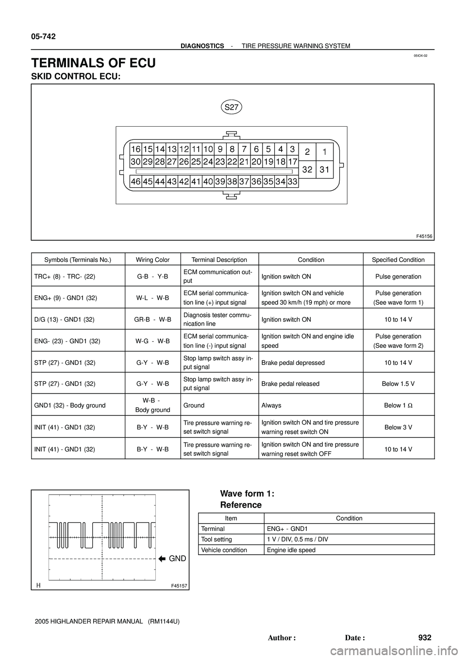
TERMINALS OF ECU
SKID CONTROL ECU:
Symbols (Terminals No.)Wiring ColorTerminal DescriptionConditionSpecified Condition
TRC+ (8) - TRC- (22)G-B - Y-BECM communication out-
putIgnition switch ONPulse generation
ENG+ (9) - GND1 (32)W-L - W-BECM serial communica-
tion line (+) input signalIgnition switch ON and vehicle
speed 30 km/h (19 mph) or morePulse generation
(See wave form 1)
D/G (13) - GND1 (32)GR-B - W-BDiagnosis tester commu-
nication lineIgnition switch ON10 to 14 V
ENG- (23) - GND1 (32)W-G - W-BECM serial communica-
tion line (-) input signalIgnition switch ON and engine idle
speedPulse generation
(See wave form 2)
STP (27) - GND1 (32)G-Y - W-BStop lamp switch assy in-
put signalBrake pedal depressed10 to 14 V
STP (27) - GND1 (32)G-Y - W-BStop lamp switch assy in-
put signalBrake pedal releasedBelow 1.5 V
GND1 (32) - Body groundW-B -
Body groundGroundAlwaysBelow 1 W
INIT (41) - GND1 (32)B-Y - W-BTire pressure warning re-
set switch signalIgnition switch ON and tire pressure
warning reset switch ONBelow 3 V
INIT (41) - GND1 (32)B-Y - W-BTire pressure warning re-
set switch signalIgnition switch ON and tire pressure
warning reset switch OFF10 to 14 V
Wave form 1:
Reference
ItemCondition
TerminalENG+ - GND1
Tool setting1 V / DIV, 0.5 ms / DIV
Vehicle conditionEngine idle speed