Page 785 of 2572
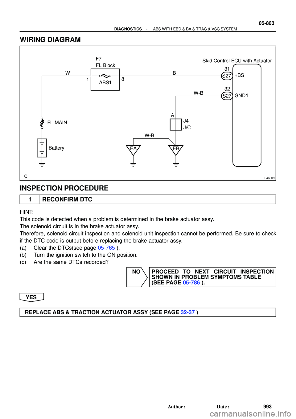
F46309
Skid Control ECU with Actuator F7
FL Block
FL MAIN
Battery
EA EB ABS1+BS
GND1
J4
J/C 1831
32
AB W
W-BS27
S27 W-B
- DIAGNOSTICSABS WITH EBD & BA & TRAC & VSC SYSTEM
05-803
993 Author�: Date�:
WIRING DIAGRAM
INSPECTION PROCEDURE
1 RECONFIRM DTC
HINT:
This code is detected when a problem is determined in the brake actuator assy.
The solenoid circuit is in the brake actuator assy.
Therefore, solenoid circuit inspection and solenoid unit inspection cannot be performed. Be sure to check
if the DTC code is output before replacing the brake actuator assy.
(a) Clear the DTCs(see page 05-765).
(b) Turn the ignition switch to the ON position.
(c) Are the same DTCs recorded?
NO PROCEED TO NEXT CIRCUIT INSPECTION
SHOWN IN PROBLEM SYMPTOMS TABLE
(SEE PAGE 05-786).
YES
REPLACE ABS & TRACTION ACTUATOR ASSY (SEE PAGE 32-37)
Page 790 of 2572

BM
3
ABS R/B:
S27
I37487
5
3
ABS R/B:
05-808
- DIAGNOSTICSABS WITH EBD & BA & TRAC & VSC SYSTEM
998 Author�: Date�:
6 CHECK HARNESS AND CONNECTOR(VSC M")
I37488
Skid Control ECU
(harness side connector)
BM
3
ABS R/B:
S27
I37487
5
3
ABS R/B:
05-808
- DIAGNOSTICSABS WITH EBD & BA & TRAC & VSC SYSTEM
998 Author�: Date�:
6 CHECK HARNESS AND CONNECTOR(VSC MOTOR RELAY - SKID CONTROL
ECU)
(a) Disconnect the skid control ECU connector.
(b) Measure the resistance according to the value(s) in the
table below.
Standard:
Tester ConnectionSpecified Condition
S27-2 (BM) - 3 (ABS R/B)Below 1 W
(c) Measure the resistance according to the value(s) in the
table below.
Standard:
Tester ConnectionSpecified Condition
S27-2 BM - Body ground10 kW or higher
NG REPAIR OR REPLACE HARNESS OR
CONNECTOR
OK
7 CHECK HARNESS AND CONNECTOR(VSC MOTOR RELAY - SKID CONTROL
RELAY)
(a) Remove the ABS motor relay and skid control relay from
ABS R/B.
(b) Measure the resistance according to the value(s) in the
table below.
Standard:
Tester ConnectionSpecified Condition
5 (ABS MOTOR Relay) -
3 (Skid Control Relay)Below 1 W
NG REPAIR OR REPLACE HARNESS OR
CONNECTOR
OK
REPLACE ABS & TRACTION ACTUATOR ASSY (SEE PAGE 32-37)
Page 791 of 2572

F46309
Skid Control ECU with Actuator F7
FL Block
FL MAIN
Battery
EA EB ABS1+BS
GND1
J4
J/C 1831
32
AB W
W-BS27
S27 W-B
- DIAGNOSTICSABS WITH EBD & BA & TRAC & VSC SYSTEM
05-809
999 Author�: Date�:
DTC C0278/11 OPEN CIRCUIT IN ABS SOLENOID RELAY
CIRCUIT
DTC C0279/12 SHORT CIRCUIT IN ABS SOLENOID RELAY
CIRCUIT
CIRCUIT DESCRIPTION
The ABS solenoid relay is built in the ABS & TRACTION Actuator assy. This relay supplies power to each
ABS solenoid. If the initial check is OK, after the ignition switch is turned to the ON position, the relay goes
on.
DTC No.DTC Detecting ConditionTrouble Area
C0278/11
When any of the following (1 to 2) is detected:
(1) All the following conditions continues for at least 0.2
seconds.
�IG voltage is between 9.5 and 17.2 V.
�Relay contact is open when the relay is ON.
(2) All the following conditions continues for at least 0.2
seconds.
�IG voltage is 9.5 V or less when the relay is ON.
�Relay contact remains open.
�ABS No.1 fuse
�ABS SOL relay
�ABS SOL relay circuit
�ABS & TRAC actuator
C0279/12
The following condition continue for at least 0.2 seconds.
�Relay contact is closed immediately after turning IG switch
to the ON position when the relay is OFF.�ABS No.1 fuse
�ABS SOL relay
�ABS SOL relay circuit
�ABS & TRAC actuator
WIRING DIAGRAM
05CD5-19
Page 792 of 2572
S27
05-810
- DIAGNOSTICSABS WITH EBD & BA & TRAC & VSC SYSTEM
1000 Author�: Date�:
INSPECTION PROCEDURE
1 INSPECT FUSE(AB")
F40458
ABS1 FL BLOCK
G24767
GND1
+BS Skid Control ECU
(harness side connector)S27
05-810
- DIAGNOSTICSABS WITH EBD & BA & TRAC & VSC SYSTEM
1000 Author�: Date�:
INSPECTION PROCEDURE
1 INSPECT FUSE(ABS1 FUSE)
(a) Remove ABS1 fuse from the FL BLOCK.
(b) Check continuity of ABS1 fuse.
Standard:
ABS No.2 fuseBelow 1 W (Continuity)
NG CHECK FOR SHORT IN ALL HARNESS AND
CONNECTOR CONNECTED TO FUSE AND
REPLACE FUSE
OK
2 INSPECT SKID CONTROL ECU CONNECTOR(+BS TERMINAL VOLTAGE)
(a) Disconnect the skid control ECU connector.
(b) Turn the ignition switch to the ON position.
(c) Measure the voltage according to the value(s) in the table
below.
Standard:
Tester ConnectionSpecified Condition
S27-31 (+BS) - S27-32 (GND1)10 to 14 V
NG Go to step 4
OK
3 RECONFIRM DTC
(a) Clear the DTCs (see page 05-765).
(b) Turn the ignition switch to the ON position.
(c) Are the same DTCs recorded?
NOTICE:
When replacing ABS & TRACTION ACTUATOR ASSY, perform zero point calibration
(see page 05-765).
NO PROCEED TO NEXT CIRCUIT INSPECTION
SHOWN IN PROBLEM SYMPTOMS TABLE
(SEE PAGE 05-786)
YES
REPLACE ABS & TRACTION ACTUATOR ASSY (SEE PAGE 32-37)
Page 793 of 2572
G24767
GND1
Skid Control ECU
(harness side connector)S27
- DIAGNOSTICSABS WITH EBD & BA & TRAC & VSC SYSTEM
05-81 1
1001 Author�: Date�:
4 INSPECT SKID CONTROL ECU CONNECTOR(GND TERMINAL CONTINUITY)
(a) Disconnect the skid control ECU connector.
(b) Measure the resistance according to the value(s) in the
table below.
Standard:
Tester ConnectionSpecified Condition
S27-32 (GND1) - Body groundBelow 1 W
NG REPAIR OR REPLACE HARNESS OR
CONNECTOR
OK
5 RECONFIRM DTC
(a) Clear the DTCs (see page 05-765).
(b) Turn the ignition switch to the ON position.
(c) Are the same DTCs recorded? (see page 05-765).
HINT:
It is suspect that the DTCs output was caused by the poor connection of the connector terminal.
NO PROCEED TO NEXT CIRCUIT INSPECTION
SHOWN IN PROBLEM SYMPTOMS TABLE
(SEE PAGE 05-786)
YES
REPLACE ABS & TRACTION ACTUATOR ASSY (SEE PAGE 32-37)
Page 796 of 2572

ECM
TRC+
TRC-
TRC+
TRC-S27
E5
G26183
ECME7
E1
05-814
- DIAGNOSTICSABS WITH EBD & BA & TRAC & VSC SYSTEM
1004 Author�: Da")
F45165F44428F45351
ENG-
ENG+ENG-ENG+
Skid Control ECU
(harness side connector)
ECM
TRC+
TRC-
TRC+
TRC-S27
E5
G26183
ECME7
E1
05-814
- DIAGNOSTICSABS WITH EBD & BA & TRAC & VSC SYSTEM
1004 Author�: Date�:
INSPECTION PROCEDURE
1 CHECK HARNESS AND CONNECTOR(ECM - SKID CONTROL ECU)
(a) Disconnect the skid control ECU connector and ECM
connector.
(b) Measure the resistance according to the value(s) in the
table below.
Standard:
Tester ConnectionSpecified Condition
S27-8 (TRC+) - E5-25 (TRC+)Below 1 W
S27-22 (TRC-) - E5-31 (TRC-)Below 1 W
S27-9 (ENG+) - E5-24 (ENG+)Below 1 W
S27-23 (ENG-) - E5-30 (ENG-)Below 1 W
(c) Measure the resistance according to the value(s) in the
table below.
Standard:
Tester ConnectionSpecified Condition
S27-8 (TRC+) - Body ground10 kW or higher
S27-22 (TRC-) - Body ground10 kW or higher
S27-9 (ENG+) - Body ground10 kW or higher
S27-23 (ENG-) - Body ground10 kW or higher
NG REPAIR OR REPLACE HARNESS OR
CONNECTOR
OK
2 CHECK HARNESS AND CONNECTOR(E1 OF ECM - BODY GROUND)
(a) Disconnect the ECM connector.
(b) Measure the resistance according to the value(s) in the
table below.
Standard:
Tester ConnectionSpecified Condition
E7-1 (E1) - Body groundBelow 1 W
NG REPAIR OR REPLACE HARNESS OR
CONNECTOR
OK
REPLACE ABS & TRACTION ACTUATOR ASSY (SEE PAGE 32-37)
Page 802 of 2572

G26185
ECM
NEOE5
A20293
4.5 to 14 V
Below 1 V20 V/DIV, 1 ms/DIV Pulse
Generation
05-820
- DIAGNOSTICSABS WITH EBD & BA & TRAC & VSC SYSTEM
1010 Author�: Date�:
2 INSPECT ECM TERMINAL VOLTAGE(NEO TERMINAL)
(a) Reconnect the ECM connector and the skid control ECU
connector.
(b) Check the signal waveform between terminal NEO
(E5-17) of the ECM and body ground for the engine
conditions below.
OK:
Tester ConnectionEngine ConditionSpecified condition
E5-17 (NEO) - Body
groundOFF (Ignition switch ON)4.5 to 14 V or below 1 V
E5-17 (NEO) - Body
groundON (Idling)Pulse generation
(4.5 to 14 V e below 1 V)
NG REPLACE ECM
OK
3 CHECK IF SKID CONTROL ECU CONNECTOR IS SECURELY CONNECTED
NG CONNECT CONNECTOR TO ECU
OK
4 RECONFIRM DTC
(a) Clear the DTCs (see page 05-765).
(b) Turn the ignition switch to the ON position.
(c) Are the same DTCs recorded?
NO PROCEED TO NEXT CIRCUIT INSPECTION
SHOWN IN PROBLEM SYMPTOMS TABLE
(SEE PAGE 05-786)
YES
REPLACE ABS & TRACTION ACTUATOR ASSY(SEE PAGE 32-37)
Page 811 of 2572

S27
G24767
GND1
Skid Control ECU
(harness side connector)
S27
- DIAGNOSTICSABS WITH EBD & BA & TRAC & VSC SYSTEM
05-829
1019 Author�: Date�:")
G24767
GND1IG1
Skid Control ECU
(harness side connector)
S27
G24767
GND1
Skid Control ECU
(harness side connector)
S27
- DIAGNOSTICSABS WITH EBD & BA & TRAC & VSC SYSTEM
05-829
1019 Author�: Date�:
3 INSPECT SKID CONTROL ECU TERMINAL VOLTAGE(IG1 TERMINAL)
WHEN USING HAND-HELD TESTER:
(a) Connect the hand-held tester to the DLC3.
(b) Start the engine.
(c) Select the DATA LIST mode on the hand-held tester.
(d) Read the voltage condition output from the ECU displayed on the hand-held tester.
ItemMeasurement Item /
Range (Display)Normal Condition
IG VOLTAGEECU power supply voltage /
TOO LOW / NORMALNORMAL: 9.5 V or over
TOO LOW: Below 9.5 V
OK:
ºNormalº is displayed.
WHEN NOT USING HAND-HELD TESTER:
(a) Disconnect the skid control ECU connector S27.
(b) Turn the ignition switch to the ON position.
(c) Measure the voltage according to the value(s) in the table
below.
Standard:
Tester ConnectionSpecified Condition
S27-46 (IG1) - S27-32 (GND1)10 to 14 V
NG Go to step 4
OK
REPLACE ABS & TRACTION ACTUATOR ASSY (SEE PAGE 32-37)
4 INSPECT SKID CONTROL ECU CONNECTOR(GND TERMINAL CONTINUITY)
(a) Disconnect the skid control ECU connector S27.
(b) Measure the resistance according to the value(s) in the
table below.
Standard:
Tester ConnectionSpecified Condition
S27-32 (GND1) - Body groundBelow 1 W
NG REPAIR OR REPLACE HARNESS OR
CONNECTOR (GND TERMINAL - BODY
GROUND)
OK
CHECK AND REPAIR HARNESS AND CONNECTOR (IG1 TERMINAL - BATTERY)