Page 1433 of 2572
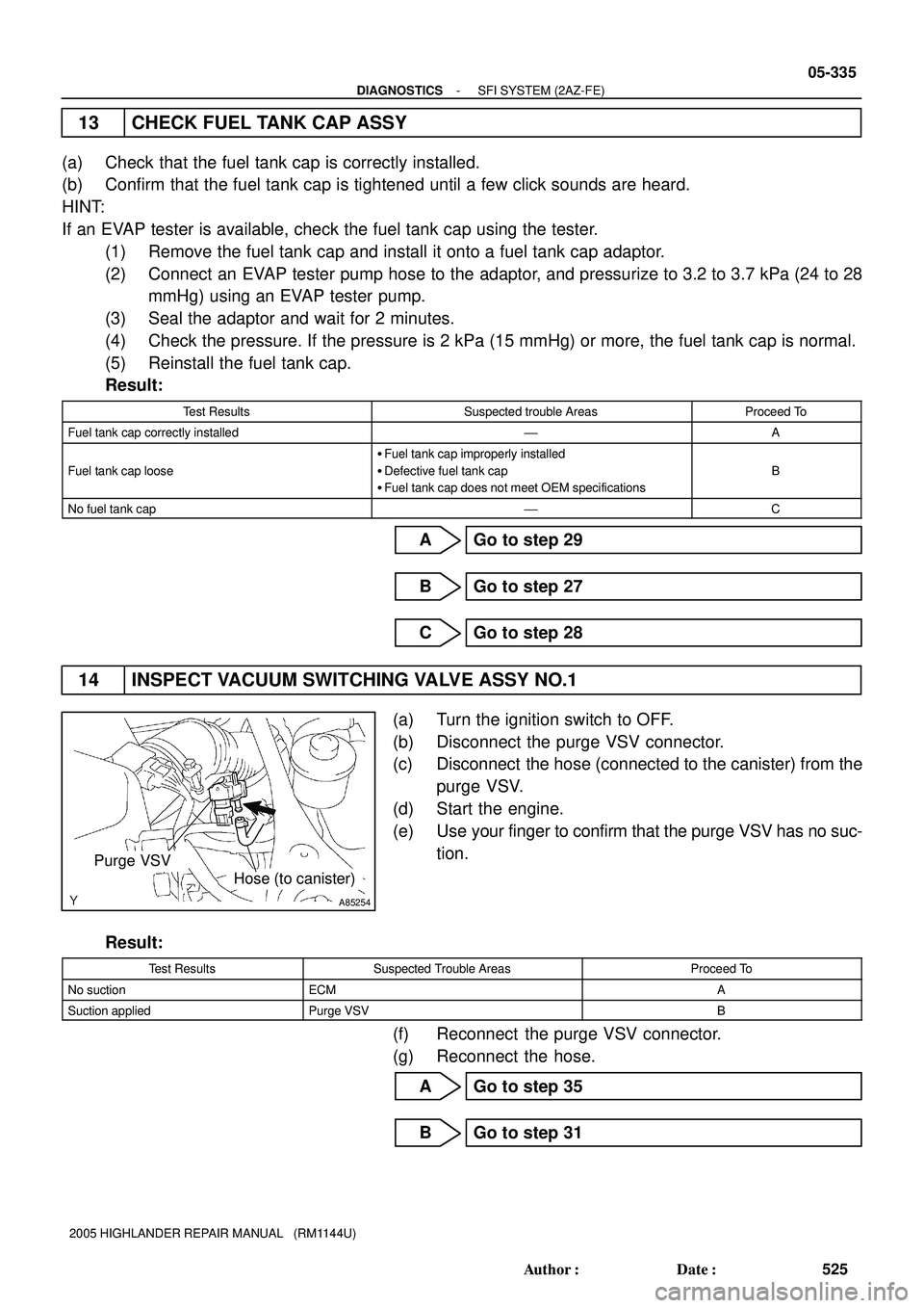
A85254
Purge VSV
Hose (to canister)
- DIAGNOSTICSSFI SYSTEM (2AZ-FE)
05-335
525 Author�: Date�:
2005 HIGHLANDER REPAIR MANUAL (RM1144U)
13 CHECK FUEL TANK CAP ASSY
(a) Check that the fuel tank cap is correctly installed.
(b) Confirm that the fuel tank cap is tightened until a few click sounds are heard.
HINT:
If an EVAP tester is available, check the fuel tank cap using the tester.
(1) Remove the fuel tank cap and install it onto a fuel tank cap adaptor.
(2) Connect an EVAP tester pump hose to the adaptor, and pressurize to 3.2 to 3.7 kPa (24 to 28
mmHg) using an EVAP tester pump.
(3) Seal the adaptor and wait for 2 minutes.
(4) Check the pressure. If the pressure is 2 kPa (15 mmHg) or more, the fuel tank cap is normal.
(5) Reinstall the fuel tank cap.
Result:
Test ResultsSuspected trouble AreasProceed To
Fuel tank cap correctly installed'A
Fuel tank cap loose
�Fuel tank cap improperly installed
�Defective fuel tank cap
�Fuel tank cap does not meet OEM specifications
B
No fuel tank cap'C
A Go to step 29
B Go to step 27
C Go to step 28
14 INSPECT VACUUM SWITCHING VALVE ASSY NO.1
(a) Turn the ignition switch to OFF.
(b) Disconnect the purge VSV connector.
(c) Disconnect the hose (connected to the canister) from the
purge VSV.
(d) Start the engine.
(e) Use your finger to confirm that the purge VSV has no suc-
tion.
Result:
Test ResultsSuspected Trouble AreasProceed To
No suctionECMA
Suction appliedPurge VSVB
(f) Reconnect the purge VSV connector.
(g) Reconnect the hose.
A Go to step 35
B Go to step 31
Page 1440 of 2572
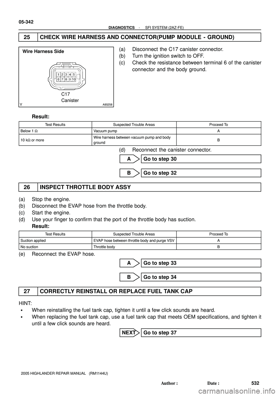
A85258
Wire Harness Side
C17
Canister
05-342
- DIAGNOSTICSSFI SYSTEM (2AZ-FE)
532 Author�: Date�:
2005 HIGHLANDER REPAIR MANUAL (RM1144U)
25 CHECK WIRE HARNESS AND CONNECTOR(PUMP MODULE - GROUND)
(a) Disconnect the C17 canister connector.
(b) Turn the ignition switch to OFF.
(c) Check the resistance between terminal 6 of the canister
connector and the body ground.
Result:
Test ResultsSuspected Trouble AreasProceed To
Below 1 WVacuum pumpA
10 kW or moreWire harness between vacuum pump and body
groundB
(d) Reconnect the canister connector.
A Go to step 30
B Go to step 32
26 INSPECT THROTTLE BODY ASSY
(a) Stop the engine.
(b) Disconnect the EVAP hose from the throttle body.
(c) Start the engine.
(d) Use your finger to confirm that the port of the throttle body has suction.
Result:
Test ResultsSuspected Trouble AreasProceed To
Suction appliedEVAP hose between throttle body and purge VSVA
No suctionThrottle bodyB
(e) Reconnect the EVAP hose.
A Go to step 33
B Go to step 34
27 CORRECTLY REINSTALL OR REPLACE FUEL TANK CAP
HINT:
�When reinstalling the fuel tank cap, tighten it until a few click sounds are heard.
�When replacing the fuel tank cap, use a fuel tank cap that meets OEM specifications, and tighten it
until a few click sounds are heard.
NEXT Go to step 37
Page 1441 of 2572
A85255
Pressure Gauge
Pressure
B06546
- DIAGNOSTICSSFI SYSTEM (2AZ-FE)
05-343
533 Author�: Date�:
2005 HIGHLANDER REPAIR MANUAL (RM1144U)
28 REPLACE FUEL TANK CAP ASSY
HINT:
When installing the fuel tank cap, tighten it until a few click sounds are heard.
NEXT Go to step 37
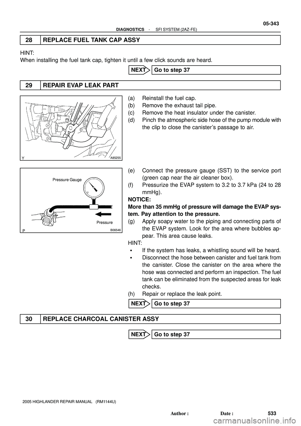
29 REPAIR EVAP LEAK PART
(a) Reinstall the fuel cap.
(b) Remove the exhaust tail pipe.
(c) Remove the heat insulator under the canister.
(d) Pinch the atmospheric side hose of the pump module with
the clip to close the canister's passage to air.
(e) Connect the pressure gauge (SST) to the service port
(green cap near the air cleaner box).
(f) Pressurize the EVAP system to 3.2 to 3.7 kPa (24 to 28
mmHg).
NOTICE:
More than 35 mmHg of pressure will damage the EVAP sys-
tem. Pay attention to the pressure.
(g) Apply soapy water to the piping and connecting parts of
the EVAP system. Look for the area where bubbles ap-
pear. This area cause leaks.
HINT:
�If the system has leaks, a whistling sound will be heard.
�Disconnect the hose between canister and fuel tank from
the canister. Close the canister on the area where the
hose was connected and perform an inspection. The fuel
tank can be eliminated from the suspected areas for leak
checks.
(h) Repair or replace the leak point.
NEXT Go to step 37
30 REPLACE CHARCOAL CANISTER ASSY
NEXT Go to step 37
Page 1444 of 2572
05-346
- DIAGNOSTICSSFI SYSTEM (2AZ-FE)
536 Author�: Date�:
2005 HIGHLANDER REPAIR MANUAL (RM1144U)
Monitor Confirmation
HINT:
After a repair, check Monitor Status by performing the Key-Off Monitor Confirmation and Purge Flow Monitor
Confirmation described below.
1. KEY-OFF MONITOR CONFIRMATION
(a) Preconditions
The monitor will not run unless:
�The vehicle has been driven for 10 minutes or more (in a city area or on a free way)
�The fuel tank is less than 90% full
�The altitude is less than 8,000 ft (2,400 m)
�The Engine Coolant Temperature (ECT) is between 4.4�C and 35�C (40�F and 95�F)
�The Intake Air Temperature (IAT) is between 4.4�C and 35�C (40�F and 95�F)
�The vehicle remains stationary (the vehicle speed is 0 mph [0 km/h])
(b) Monitor Conditions
(1) Allow the engine to idle for at least 5 minutes.
(2) Turn the ignition switch OFF and wait for 6 hours (8 or 10.5 hours).
HINT:
Do not start the engine until checking MONITOR STATUS. If the engine is started, the steps described above
must be repeated.
(c) Monitor Status
(1) Connect a hand-held tester to the DLC3.
(2) Turn the ignition switch ON and turn the tester ON.
(3) On the tester, select the following menu items: DIAGNOSIS / ENHANCED OBD II / MONITOR
STATUS.
(4) Check the Monitor Status displayed on the tester.
HINT:
If INCMP is displayed, the monitor is not completed. Make sure that the preconditions have been met, and
perform the Monitor Conditions again.
2. PURGE FLOW MONITOR CONFIRMATION (P0441)
HINT:
Perform this monitor confirmation after the Key-Off Monitor Confirmation shows COMPL (complete).
(a) Preconditions
The monitor will not run unless:
�The vehicle has been driven for 10 minutes or more (in a city area or on a free way)
�The ECT is between 4.4�C and 35�C (40�F and 95�F)
�The IAT is between 4.4�C and 35�C (40�F and 95�F)
(b) Monitor Conditions
(1) Release the pressure from the fuel tank by removing and reinstalling the fuel tank cap.
(2) Warm the engine up until the ECT reaches more than 75�C (167�F).
(3) Increase the engine speed to 3,000 rpm once.
(4) Allow the engine to idle and turn A/C ON for 1 minute.
(c) Monitor Status
(1) Turn the ignition switch OFF (where ON or the engine is running).
(2) Connect a hand-held tester to the DLC3.
(3) Turn the ignition switch to ON and turn the tester ON.
(4) On the tester, select the following menu items: DIAGNOSIS / ENHANCED OBD II / MONITOR
STATUS.
(5) Check the Monitor Status displayed on the tester.
Page 1758 of 2572
A85838
Waveform of A/F Sensor
Before CatalystWaveform of Heated Oxygen Sensor
After Catalyst Normal Catalyst
Deteriorated Catalyst Waveform of A/F Sensor
Before CatalystWaveform of Heated Oxygen Sensor
After Catalyst 3.5 V
3.0 V
3.5 V
3.0 V1.0 V
0.5 V
1.0 V
0.5 V
10 seconds 10 seconds
0 V 0 V 05-184
- DIAGNOSTICSSFI SYSTEM (2AZ-FE)
374 Author�: Date�:
2005 HIGHLANDER REPAIR MANUAL (RM1144U)
DTC P0420 CATALYST SYSTEM EFFICIENCY BELOW
THRESHOLD (BANK 1)
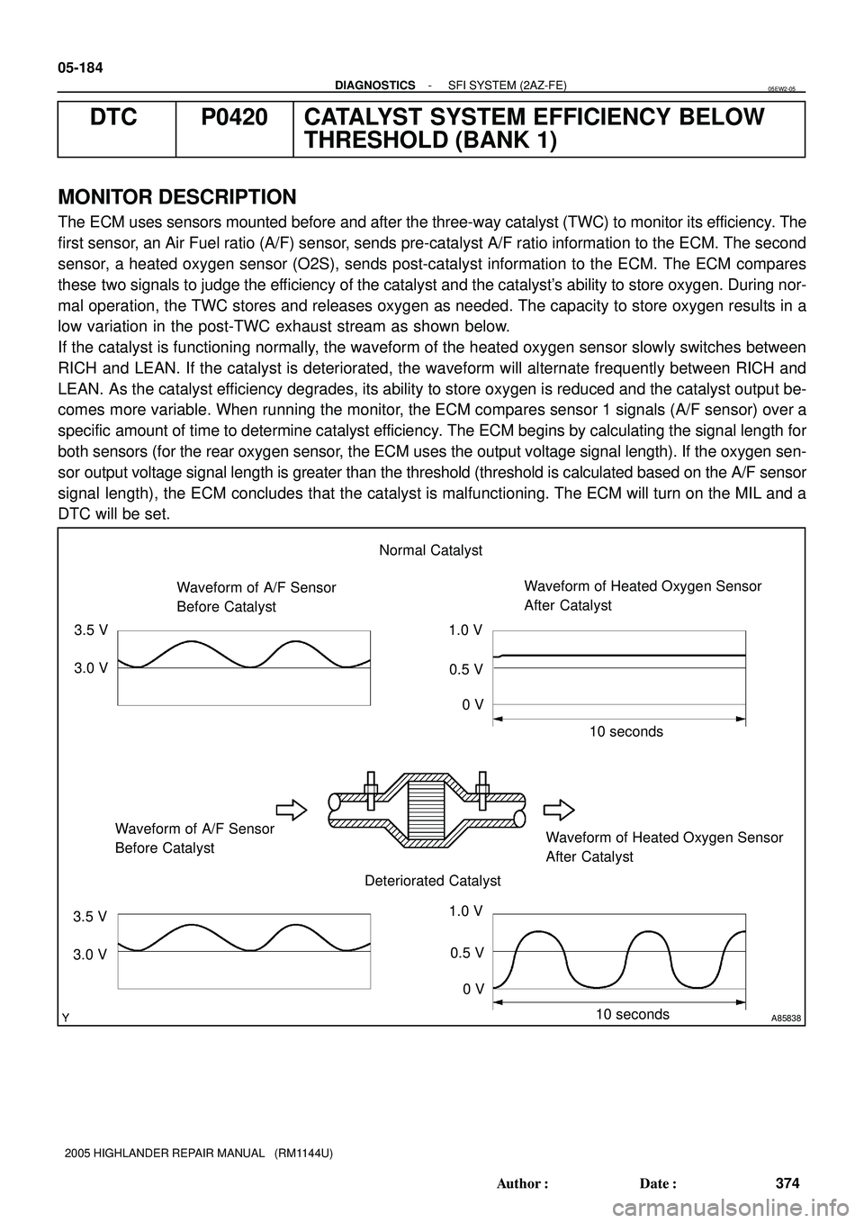
MONITOR DESCRIPTION
The ECM uses sensors mounted before and after the three-way catalyst (TWC) to monitor its efficiency. The
first sensor, an Air Fuel ratio (A/F) sensor, sends pre-catalyst A/F ratio information to the ECM. The second
sensor, a heated oxygen sensor (O2S), sends post-catalyst information to the ECM. The ECM compares
these two signals to judge the efficiency of the catalyst and the catalyst's ability to store oxygen. During nor-
mal operation, the TWC stores and releases oxygen as needed. The capacity to store oxygen results in a
low variation in the post-TWC exhaust stream as shown below.
If the catalyst is functioning normally, the waveform of the heated oxygen sensor slowly switches between
RICH and LEAN. If the catalyst is deteriorated, the waveform will alternate frequently between RICH and
LEAN. As the catalyst efficiency degrades, its ability to store oxygen is reduced and the catalyst output be-
comes more variable. When running the monitor, the ECM compares sensor 1 signals (A/F sensor) over a
specific amount of time to determine catalyst efficiency. The ECM begins by calculating the signal length for
both sensors (for the rear oxygen sensor, the ECM uses the output voltage signal length). If the oxygen sen-
sor output voltage signal length is greater than the threshold (threshold is calculated based on the A/F sensor
signal length), the ECM concludes that the catalyst is malfunctioning. The ECM will turn on the MIL and a
DTC will be set.
05EW2-05
Page 1771 of 2572
05-564
- DIAGNOSTICSSFI SYSTEM (3MZ-FE)
754 Author�: Date�:
2005 HIGHLANDER REPAIR MANUAL (RM1144U)DTC No.
DTC Detection ConditionTrouble Area
P0442
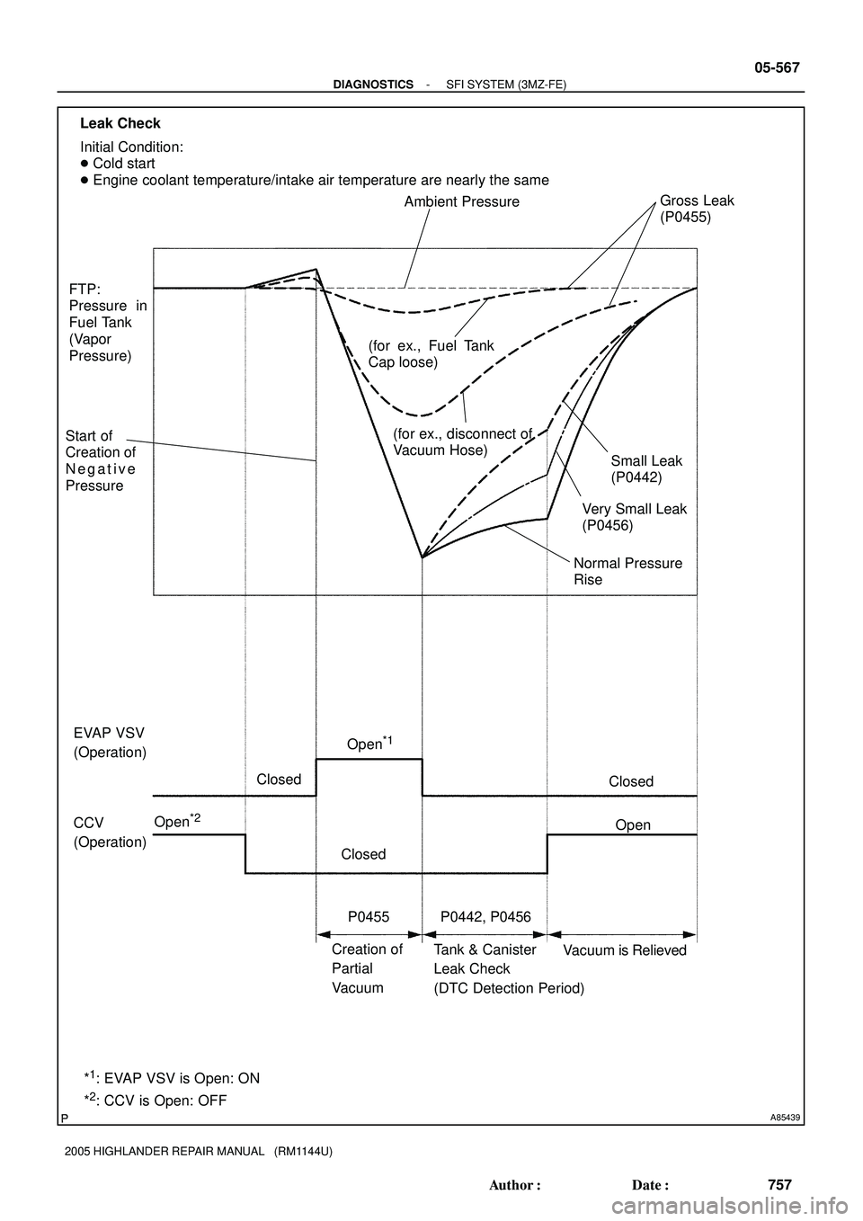
P0455
P0456
�Cold engine start.
�EVAP VSV has been operated and turned OFF, sealing nega-
tive pressure (vacuum) in system.
�ECM begins to monitor fuel tank pressure increase and one
of the following occurs (2 trip detection logic):
(a) Rapid, sharp increase in pressure occurs, indicating small
leak in EVAP system. DTC P0442 is set.
(b) Negative pressure (vacuum) is not strong enough, indicat-
ing large hole in EVAP system. DTC P0455 is set.
(c) Increase in pressure above expected amount occurs, indi-
cating small leak in EVAP system. DTC P0456 is set.
�Vacuum hose has cracks, holes, or is blocked, damaged or
disconnected
�Fuel tank cap incorrectly installed
�Fuel tank cap has cracks or is damaged
�Open or short in vapor pressure sensor circuit
�Vapor pressure sensor
�Open or short in EVAP VSV circuit
�EVAP VSV
�Open or short in CCV circuit
� CCV
�Fuel tank has cracks, holes, or is damaged
�Charcoal canister has cracks, holes, or is damaged
�Fuel tank over fill check valve cracks, or is damaged
�ECM
Page 1772 of 2572
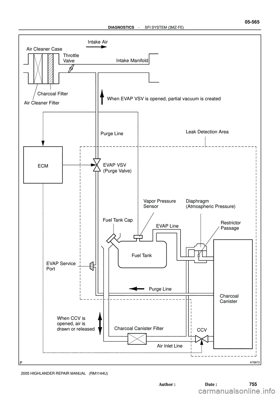
A76973
ECM
Fuel Tank
Charcoal
Canister EVAP VSV
Vapor Pressure
Sensor
CCV EVAP Service
PortIntake Air
Throttle
Valve
Fuel Tank Cap
Air Cleaner Case
Charcoal Canister Filter Charcoal Filter
Intake Manifold
Purge Line
Air Inlet Line EVAP Line Purge Line
Diaphragm
(Atmospheric Pressure)
Restrictor
Passage
When EVAP VSV is opened, partial vacuum is created
When CCV is
opened, air is
drawn or released
Leak Detection Area
(Purge Valve)
Air Cleaner Filter
- DIAGNOSTICSSFI SYSTEM (3MZ-FE)
05-565
755 Author�: Date�:
2005 HIGHLANDER REPAIR MANUAL (RM1144U)
Page 1774 of 2572
A85439
CCV
(Operation) EVAP VSV
(Operation)
Creation of
Partial
VacuumTank & Canister
Leak Check
(DTC Detection Period) Open
*1
Closed
Open
*2Open Closed
Closed
P0442, P0456 FTP:
Pressure in
Fuel Tank
(Vapor
Pressure)
*
1: EVAP VSV is Open: ON
*
2: CCV is Open: OFFNormal Pressure
Rise
Vacuum is Relieved Leak Check
P0455Very Small Leak
(P0456)
Small Leak
(P0442)
Ambient PressureGross Leak
(P0455)
Start of
Creation of
Negative
PressureInitial Condition:
� Cold start
� Engine coolant temperature/intake air temperature are nearly the same
(for ex., disconnect of
Vacuum Hose) (for ex., Fuel Tank
Cap loose)
- DIAGNOSTICSSFI SYSTEM (3MZ-FE)
05-567
757 Author�: Date�:
2005 HIGHLANDER REPAIR MANUAL (RM1144U)