Page 227 of 2572

'05 HIGHLANDER_U (L/O 0409)
107
2005 HIGHLANDER from Nov. '04 Prod. (OM48570U)
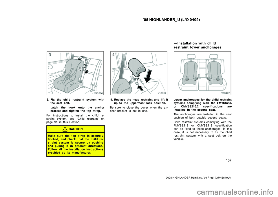
3. Fix the child restraint system with
the seat belt.
Latch the hook onto the anchor
bracket and tighten the top strap.
For instructions to install the child re-
straint system, see Child restraintº on
page 91 in this Section.
CAUTION
Make sure the top strap is securely
latched, and check that the child re-
straint system is secure by pushing
and pulling it in different directions.
Follow all the installation instructions
provided by its manufacturer.
4. Replace the head restraint and lift it
up to the uppermost lock position.
Be sure to close the cover when the an-
chor bracket is not in use.Lower anchorages for the child restraint
systems complying with the FMVSS225
or CMVSS210.2 specifications are
installed in the second seat.
The anchorages are installed in the seat
cushion of both outside second seats.
Child restraint systems complying with the
FMVSS213 or CMVSS213 specification
can be fixed to these anchorages. In this
case, it is not necessary to fix the child
restraint system with a seat belt on the
vehicle.
ÐInstallation with child
restraint lower anchorages
Page 228 of 2572
'05 HIGHLANDER_U (L/O 0409)
108
2005 HIGHLANDER from Nov. '04 Prod. (OM48570U)
3rd lock
position1st lock
position
CHILD RESTRAINT SYSTEM
INSTALLATION
1. Fold down the seatback and back to
the 1st lock position (most upright
position) until it locks into place.
Adjust the seatback to the 3rd lock
position.
Make sure the seatback is locked secure-
ly.
Canada only
Ty p e ACanada only
Ty p e B
Page 229 of 2572

'05 HIGHLANDER_U (L/O 0409)
109
2005 HIGHLANDER from Nov. '04 Prod. (OM48570U)
2. Widen the gap between the seat
cushion and seatback slightly and
confirm the position of the lower an-
chorages near the button on the
seatback.
3. Type AÐLatch the hooks of lower
straps onto the anchorages and
tighten the lower straps.
Type BÐLatch the buckles onto the
anchorages.
For owners in CanadaÐThe symbol on
a child restraint system indicates the pres-
ence of a lower connector system.
If your child restraint system has a top
strap, it should be anchored. (For the
installation of the top strap, see ÐUsing
a top strapº on page 105 in this Section.)
For installation details, refer to the instruc-
tion manual equipped with each product.CAUTION
�When using the lower anchorages
for the child restraint system, be
sure that there are no irregular ob-
jects around the anchorages or that
the seat belt is not caught.
�Push and pull the child restraint
system in different directions to be
sure it is secure. Follow all the
installation instructions provided by
its manufacturer.
�When using the lower anchorages
for the child restraint system, en-
sure that the seat is moved to the
rear- most position, with the seat-
back close to the child restraint
system.
�After securing the child restraint
system, never slide or recline the
seat.
�Do not install a child restraint sys-
tem on the second seat if it inter-
feres with the lock mechanism of
the front seats. Otherwise, the child
or front seat occupant(s) may be
killed or seriously injured in case
of sudden braking or a collision.
Page 2180 of 2572

'05 HIGHLANDER_U (L/O 0409)
iii
2005 HIGHLANDER from Nov. '04 Prod. (OM48570U)
Important information about your Toyota
Occupant restraint systems
Toyota encourages you and your family to take the time to
read Section 1- 3 of this Owner 's Manual carefully. In
terms of helping you understand how you can receive the
maximum benefit of the occupant restraint systems this
vehicle provides, Section 1- 3 of this Owner 's Manual is
the most important Section for you and your family to
read.
Section 1- 3 describes the function and operation concern-
ing seats, seat belts, SRS airbags and child restraint sys-
tems of this vehicle and some potential hazards you
should be aware of. These systems work together along
with the overall structure of this vehicle in order to provide
occupant restraint in the event of a crash. The effect of
each system can be enhanced when it is used properly
and together with other systems. No single occupant re-
straint system can, by itself, provide you or your family
with the equal level of restraint which these systems can
provide when used together. That is why it is important for
you and your family to understand the purpose and proper
use of each of these systems and how they relate to each
other.
The purpose of all occupant restraint systems is to help
reduce the possibility of death or serious injury in the
event of a collision. None of these systems, either individ-
ually or together, can ensure that there is no injury in the
event of collision. However, the more you know about
these systems and how to use them properly, the greater
your chances become of surviving an accident without
death or serious injury.
Seat belts provide the primary restraint to all occupants of
the vehicle, and every occupant of the vehicle should wear
seat belts properly at all times. Children should always be
secured in child restraint systems that are appropriate for
their age and size. SRS (Supplemental Restraint System)
airbags are, as their names imply, designed to work with,
and be supplemental to, seat belts and are not substitutes
for them. SRS airbags can be very effective in reducing
the risk of head and chest injuries by preventing contact of
the head and chest with interior portions of the vehicle.
Page 2194 of 2572

010QO-02
- INTRODUCTIONTERMS
01-41
41 Author�: Date�:
2005 HIGHLANDER REPAIR MANUAL (RM1144U)
TERMS
ABBREVIATIONS USED IN MANUAL
AbbreviationsMeaning
ABSAnti-Lock Brake System
A/CAir Conditioner
ACAlternating Current
ACCAccessory
ACISAcoustic Control Induction System
ACSDAutomatic Cold Start Device
A.D.D.Automatic Disconnecting Differential
A/FAir-Fuel Ratio
AHCActive Height Control Suspension
ALRAutomatic Locking Retractor
ALTAlternator
AMPAmplifier
ANTAntenna
Approx.Approximately
ASSYAssembly
A/T, ATMAutomatic Transmission
AT FAutomatic Transmission Fluid
AUTOAutomatic
AUXAuxiliary
AV GAverage
AV SAdaptive Variable Suspension
B+Battery Voltage
BABrake Assist
BACSBoost Altitude Compensation System
BATBattery
BDCBottom Dead Center
B/LBi-Level
B/SBore-Stroke Ratio
BTDCBefore Top Dead Center
BVSVBimetallic Vacuum Switching Valve
CANController Area Network
CBCircuit Breaker
CCoCatalytic Converter For Oxidation
CDCompact Disc
CFCornering Force
CGCenter Of Gravity
CHChannel
CKDComplete Knock Down
COMB.Combination
CPECoupe
CPSCombustion Pressure Sensor
CPUCentral Processing Unit
CRSChild Restraint System
CTRCenter
C/VCheck Valve
CVControl Valve
CWCurb Weight
DCDirect Current