Page 1509 of 2572
B65516
1
T5
Security Indicator
Lamp Assy11
13
3F W-B
IB2B
3BTheft Warning ECU Assy
2
IND 3C25 8
T4 R 3F
W-BCenter J/B
B51710
1
2
05-2024
- DIAGNOSTICSTHEFT DETERRENT SYSTEM
2214 Author�: Date�:
2005 HIGHLANDER REPAIR MANUAL (RM1144U)
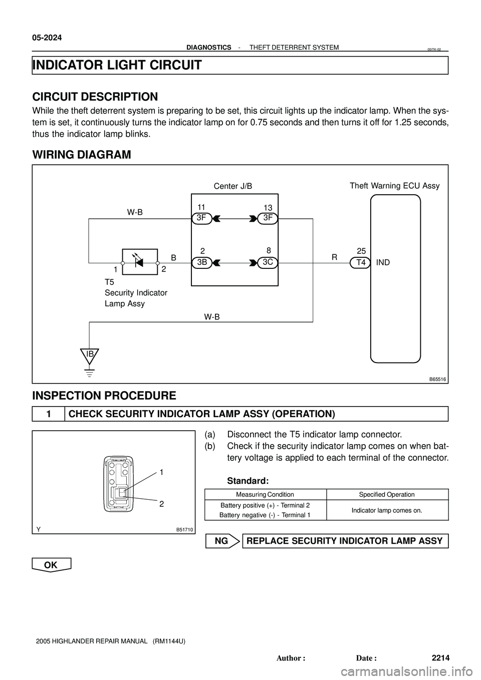
INDICATOR LIGHT CIRCUIT
CIRCUIT DESCRIPTION
While the theft deterrent system is preparing to be set, this circuit lights up the indicator lamp. When the sys-
tem is set, it continuously turns the indicator lamp on for 0.75 seconds and then turns it off for 1.25 seconds,
thus the indicator lamp blinks.
WIRING DIAGRAM
INSPECTION PROCEDURE
1 CHECK SECURITY INDICATOR LAMP ASSY (OPERATION)
(a) Disconnect the T5 indicator lamp connector.
(b) Check if the security indicator lamp comes on when bat-
tery voltage is applied to each terminal of the connector.
Standard:
Measuring ConditionSpecified Operation
Battery positive (+) - Terminal 2
Battery negative (-) - Terminal 1Indicator lamp comes on.
NG REPLACE SECURITY INDICATOR LAMP ASSY
OK
05ITK-02
Page 2020 of 2572
- DIAGNOSTICSSUPPLEMENTAL RESTRAINT SYSTEM
05-1517
1707 Author�: Date�:
2005 HIGHLANDER REPAIR MANUAL (RM1144U)
SRS WARNING LIGHT CIRCUIT MALFUNCTION (ALWAYS LIGHT
UP, WHEN DTC IS NOT OUTPUT.)
CIRCUIT DESCRIPTION
The SRS warning light is located on the combination meter.
When the SRS is normal, the SRS warning light lights up for approx. 6 seconds after the ignition switch is
turned from the LOCK position to ON position, and then turns off automatically.
If there is a malfunction in the SRS, the SRS warning light lights up to inform the driver of the abnormality.
When terminals Tc and CG of the DLC3 are connected, the DTC is displayed by blinking the SRS warning
light.
05IX2-02
Page 2024 of 2572

SRS WARNING LIGHT CIRCUIT MALFUNCTION (DOES NOT LIGHT
UP, WHEN IGNITION SWITCH IS TURN")
- DIAGNOSTICSSUPPLEMENTAL RESTRAINT SYSTEM
05-1521
1711 Author�: Date�:
2005 HIGHLANDER REPAIR MANUAL (RM1144U)
SRS WARNING LIGHT CIRCUIT MALFUNCTION (DOES NOT LIGHT
UP, WHEN IGNITION SWITCH IS TURNED TO ON)
CIRCUIT DESCRIPTION
The SRS warning light is located on the combination meter.
When the SRS is normal, the SRS warning light lights up for approx. 6 seconds after the ignition switch is
turned from the LOCK position to ON position, and then turns off automatically.
If there is a malfunction is the SRS, the SRS warning light lights up to inform the driver of the abnormality.
When terminals Tc and CG of the DLC3 are connected, the DTC is displayed by blinking the SRS warning
light.
WIRING DIAGRAM
see page 05-1517.
INSPECTION PROCEDURE
1 CHECK BATTERY
(a) Measure the voltage of the battery.
Standard: 11 to 14 V
NG REPLACE BATTERY
OK
2 CHECK WIRE HARNESS
(a) Turn the ignition switch to the LOCK position.
(b) Disconnect the negative (-) terminal cable from the battery, and wait for at least 90 seconds.
(c) Disconnect the connector from the airbag sensor assy center.
(d) Connect the negative (-) terminal cable from the battery, and wait for at least 2 seconds.
(e) Turn the ignition switch to the ON position.
(f) Measure the resistance according to the value(s) in the table below.
OK:
The SRS warning light comes on.
NG REPAIR OR REPLACE WIRE HARNESS
(COMBINATION METER - BATTERY)
OK
REPLACE COMBINATION METER ASSEMBLY (SEE PAGE 71-10)
05269-04
Page 2163 of 2572
![TOYOTA HIGHLANDER 2001 Service Repair Manual [N]
[O]
[P]
[Q]
[R]
[S]
[T]
[U]
2005 HIGHLANDER (EWD592U)
6
B HOW TO USE THIS MANUAL
Current is applied at all times through the STOP fuse to TERMINAL 2 of the stop light SW.
When the ignition SW is](/manual-img/14/57457/w960_57457-2162.png "TOYOTA HIGHLANDER 2001 Service Repair Manual [N]
[O]
[P]
[Q]
[R]
[S]
[T]
[U]
2005 HIGHLANDER (EWD592U)
6
B HOW TO USE THIS MANUAL
Current is applied at all times through the STOP fuse to TERMINAL 2 of the stop light SW.
When the ignition SW is")
[N]
[O]
[P]
[Q]
[R]
[S]
[T]
[U]
2005 HIGHLANDER (EWD592U)
6
B HOW TO USE THIS MANUAL
Current is applied at all times through the STOP fuse to TERMINAL 2 of the stop light SW.
When the ignition SW is turned on, current flows from the GAUGE fuse to TERMINAL 8 of the light failure sensor, and also flows
through the rear lights warning light to TERMINAL 4 of the light failure sensor.
Stop Light Disconnection Warning
When the ignition SW is turned on and the brake pedal is pressed (Stop light SW on), if the stop light circuit is open, the current
flowing from TERMINAL 7 of the light failure sensor to TERMINALS 1, 2 changes, so the light failure sensor detects the
disconnection and the warning circuit of the light failure sensor is activated.
As a result, the current flows from TERMINAL 4 of the light failure sensor to TERMINAL 11 to GROUND and turns the rear lights
warning light on. By pressing the brake pedal, the current flowing to TERMINAL 8 of the light failure sensor keeps the warning
circuit on and holds the warning light on until the ignition SW is turned off.
S6 Stop Light SW
2-1 : Closed with the brake pedal depressed
L4 Light Failure Sensor
1, 2, 7-Ground : Approx. 12 volts with the stop light SW on
4, 8-Ground : Approx. 12 volts with the ignition SW at ON position
11-Ground : Always continuity
: Parts Location
CodeSee PageCodeSee PageCodeSee Page
C734L436R737
H1736R637S635
: Relay Blocks
CodeSee PageRelay Blocks (Relay Block Location)
118R/B No.1 (Instrument Panel Brace LH)
: Junction Block and Wire Harness Connector
CodeSee PageJunction Block and Wire Harness (Connector Location)
IB20Instrument Panel Wire and Instrument Panel J/B (Lower Finish Panel)
3C22Instrument Panel Wire and J/B No.3 (Instrument Panel Brace LH)
: Connector Joining Wire Harness and Wire Harness
CodeSee PageJoining Wire Harness and Wire Harness (Connector Location)
IE142Floor Wire and Instrument Panel Wire (Left Kick Panel)
BV150Luggage Room Wire and Floor Wire (Luggage Room Left)
: Ground Points
CodeSee PageGround Points Location
BL50Under the Left Center Pillar
BO50Back Panel Center
: Splice Points
CodeSee PageWire Harness with Splice PointsCodeSee PageWire Harness with Splice Points
I544Cowl WireB1850Luggage Room Wire
System Outline
Service Hints
Page 2358 of 2572

05H3Y-02
F45096
USA:
Canada:USA:
Canada: ABS Warning Light BRAKE Warning
Light
VSC Warning Light SLIP Indicator Light
TRAC OFF Indicator Light
- DIAGNOSTICSABS WITH EBD & BA & TRAC & VSC SYSTEM
05-765
955 Author�: Date�:
PRE-CHECK
1. DIAGNOSIS SYSTEM
(a) Check the warning lights.
(1) Release parking brake lever.
NOTICE:
When releasing the parking brake, set the chocks to hold
the vehicle for safety.
HINT:
When the parking brake is applied or the level of the brake fluid
is low, the BRAKE warning light comes on.
(2) When the ignition switch is turned to the ON posi-
tion, check that the ABS warning light, BRAKE
warning light, VSC warning light, TRAC OFF indica-
tor light and SLIP indicator light remain on for
approx. 3 seconds.
HINT:
�If the ECU has any stored DTCs, the ABS warning light,
VSC warning light and TRAC OFF indicator light come on.
�If the indicator does not come on, inspect if the bulb is
blown out, and also the wire harness between the skid
control ECU and the combination meter.
�If the indicator remains on, proceed to troubleshooting for
the light circuit below.
Trouble AreaSee page
ABS warning light circuit05-840 or
05-844
VSC warning light circuit05-847 or
05-851
BRAKE warning light circuit05-854
TRAC OFF indicator light circuit05-859
SLIP indicator light circuit05-863
Page 2386 of 2572

7101E-06
- INSTRUMENT PANEL/METERCOMBINATION METER
71-1
3592 Author�: Date�:
COMBINATION METER
PROBLEM SYMPTOMS TABLE
Warning Lights:
SymptomSuspect AreaSee page
Check Engine warning light does not come on.
7. ECM
8. Wire Harness or Connector
9. Combination Meter Assy05-5
05-366
-
71-18
Discharge warning light does not come on.
1. ECM
2. Wire Harness or Connector
3. Combination Meter Assy05-5
05-366
-
71-18
Brake warning light does not come on.
1. Skid control ECU
2. Wire Harness or Connector
3. Combination Meter Assy05-761
-
71-18
ABS warning light does not come on.
1. ABS ECU
2. Wire Harness or Connector
3. Combination Meter Assy05-761
-
71-18
SRS warning light does not come on.
1. Airbag Sensor Assy Center
2. Wire Harness or Connector
3. Combination Meter Assy05-1200
-
71-18
Open Door warning light does not come on.
1. Refer to troubleshooting
2. Wire Harness or Connector
3. Combination Meter Assy05-1601
-
71-18
Fuel Level warning light does not come on.
1. Refer to troubleshooting
2. Wire Harness or Connector
3. Combination Meter Assy05-1893
-
71-18
Low Oil Pressure warning light does not come on.
1. Low Oil Pressure Warning Switch
2. Wire Harness or Connector
3. Combination Meter Assy71-3
-
71-18
Driver's seat belt warning light does not come on.
1. Refer to troubleshooting
2. Wire Harness or Connector
3. Combination Meter Assy05-1898
-
71-18
ºOIL LEVELº warning light does not come on.
1. Low Oil Level Sensor
2. Wire Harness or Connector
3. ECM
4. Combination Meter Assy05-5
05-366
-
05-5
05-366
71-18
ºTIRE AIR PRESSº warning light does not come on.
1. Wire Harness or Connector
2. Skid Control ECU
3. Combination Meter Assy-
05-761
71-18
Indicator Lights:
SymptomSuspect AreaSee page
Turn indicator light does not come on.
1. Turn Signal and Hazard Warning System
2. Wire Harness or Connector
3. Combination Meter Assy05-1533
-
71-18
High Beam indicator light does not come on.
1. Headlight Dimmer Switch
2. Wire Harness or Connector
3. Combination Meter Assy05-1533
-
71-18
Washer level indicator light does not come on.
1. Washer Level Warning Switch
2. Wire Harness or Connector
3. Combination Meter Assy-
-
71-18
Page:
< prev 1-8 9-16 17-24