Page 2177 of 2572

A01037
- ENGINE MECHANICALENGINE (2AZ-FE)
14-3
2496 Author�: Date�:
2005 HIGHLANDER REPAIR MANUAL (RM1144U)
9. INSPECT COMPRESSION
(a) Warm up and stop the engine.
(b) Disconnect the injector connectors.
(c) Remove the ignition coils.
(d) Remove the spark plugs.
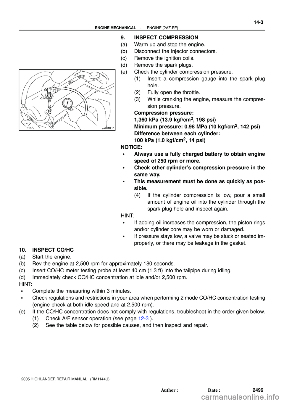
(e) Check the cylinder compression pressure.
(1) Insert a compression gauge into the spark plug
hole.
(2) Fully open the throttle.
(3) While cranking the engine, measure the compres-
sion pressure.
Compression pressure:
1,360 kPa (13.9 kgf/cm
2, 198 psi)
Minimum pressure: 0.98 MPa (10 kgf/cm
2, 142 psi)
Difference between each cylinder:
100 kPa (1.0 kgf/cm
2, 14 psi)
NOTICE:
�Always use a fully charged battery to obtain engine
speed of 250 rpm or more.
�Check other cylinder's compression pressure in the
same way.
�This measurement must be done as quickly as pos-
sible.
(4) If the cylinder compression is low, pour a small
amount of engine oil into the cylinder through the
spark plug hole and inspect again.
HINT:
�If adding oil increases the compression, the piston rings
and/or cylinder bore may be worn or damaged.
�If pressure stays low, a valve may be stuck or seated im-
properly, or there may be leakage in the gasket.
10. INSPECT CO/HC
(a) Start the engine.
(b) Rev the engine at 2,500 rpm for approximately 180 seconds.
(c) Insert CO/HC meter testing probe at least 40 cm (1.3 ft) into the tailpipe during idling.
(d) Immediately check CO/HC concentration at idle and/or 2,500 rpm.
HINT:
�Complete the measuring within 3 minutes.
�Check regulations and restrictions in your area when performing 2 mode CO/HC concentration testing
(engine check at both idle speed and at 2,500 rpm).
(e) If the CO/HC concentration does not comply with regulations, troubleshoot in the order given below.
(1) Check A/F sensor operation (see page 12-3).
(2) See the table below for possible causes, and then inspect and repair.
Page 2256 of 2572

18091-05
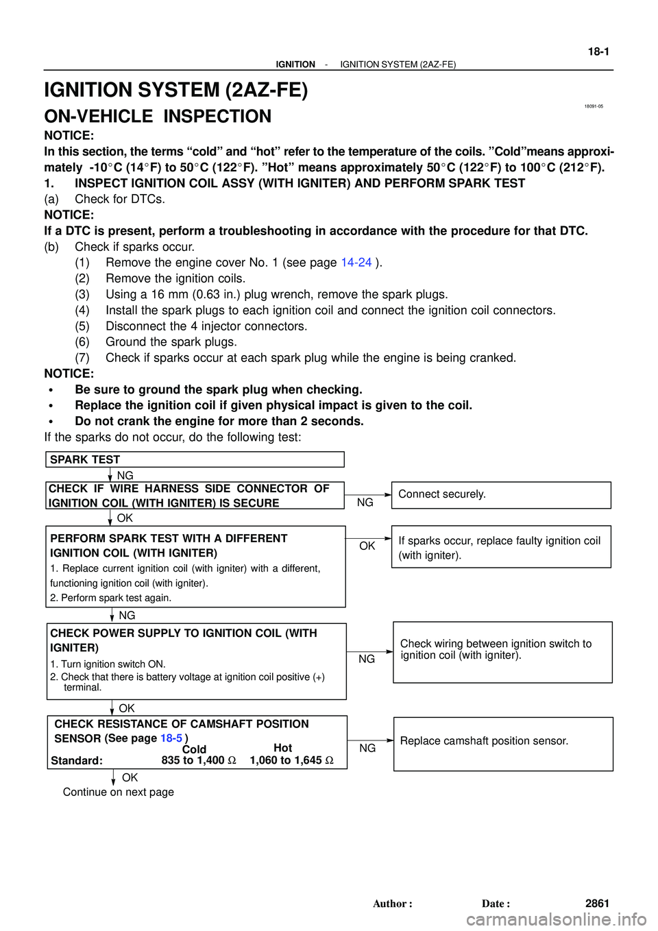
CHECK POWER SUPPLY TO IGNITION COIL (WITH
IGNITER)
SPARK TEST
1. Turn ignition switch ON.
2. Check that there is battery voltage at ignition coil positive (+)
terminal.
CHECK IF WIRE HARNESS SIDE CONNECTOR OF
IGNITION COIL (WITH IGNITER) IS SECUREConnect securely.
Check wiring between ignition switch to
ignition coil (with igniter).
NG
OK
OKNG
NG PERFORM SPARK TEST WITH A DIFFERENT
IGNITION COIL (WITH IGNITER)
1. Replace current ignition coil (with igniter) with a different,
functioning ignition coil (with igniter).
2. Perform spark test again.
OKIf sparks occur, replace faulty ignition coil
(with igniter).
NG
Continue on next page
Standard:ColdHot
1,060 to 1,645 W
OKNG
835 to 1,400 WReplace camshaft position sensor. CHECK RESISTANCE OF CAMSHAFT POSITION
SENSOR (See page 18-5)
- IGNITIONIGNITION SYSTEM (2AZ-FE)
18-1
2861 Author�: Date�:
IGNITION SYSTEM (2AZ-FE)
ON-VEHICLE INSPECTION
NOTICE:
In this section, the terms coldº and hotº refer to the temperature of the coils. ºColdºmeans approxi-
mately -10�C (14�F) to 50�C (122�F). ºHotº means approximately 50�C (122�F) to 100�C (212�F).
1. INSPECT IGNITION COIL ASSY (WITH IGNITER) AND PERFORM SPARK TEST
(a) Check for DTCs.
NOTICE:
If a DTC is present, perform a troubleshooting in accordance with the procedure for that DTC.
(b) Check if sparks occur.
(1) Remove the engine cover No. 1 (see page 14-24).
(2) Remove the ignition coils.
(3) Using a 16 mm (0.63 in.) plug wrench, remove the spark plugs.
(4) Install the spark plugs to each ignition coil and connect the ignition coil connectors.
(5) Disconnect the 4 injector connectors.
(6) Ground the spark plugs.
(7) Check if sparks occur at each spark plug while the engine is being cranked.
NOTICE:
�Be sure to ground the spark plug when checking.
�Replace the ignition coil if given physical impact is given to the coil.
�Do not crank the engine for more than 2 seconds.
If the sparks do not occur, do the following test:
Page 2257 of 2572
Replace crankshaft position sensor. CHECK RESISTANCE OF CRANKSHAFT POSITION
Standard:Cold Hot
985 to 1,600 W1,265 to 1,890 W
CHECK IGT SIGNAL FROM ECM
REPAIR WIRING BETWEEN IGNITION COIL AND ECM
OKNG
NG SENSOR (See page 18-6)
OK (See page 05-174)Check ECM (see page 05-32).
OK Continued from previous page 18-2
- IGNITIONIGNITION SYSTEM (2AZ-FE)
2862 Author�: Date�:
(8) Using a 16 mm (0.63 in.) plug wrench, install the spark plugs.
Torque: 19 NVm (194 kgfVcm, 14 ftVlbf)
(9) Install the ignition coils.
Torque: 9.0 NVm (92 kgfVcm, 80 in.Vlbf)
(10) Install the engine cover No. 1.
Torque: 9.0 NVm (92 kgfVcm, 80 in.Vlbf)
Page:
< prev 1-8 9-16 17-24