Page 2153 of 2572

2005 HIGHLANDER (EWD592U)
316
I GROUND POINT
Theft Deterr ent
Indicator Light
Remote Control
Mirror SW
TRAC Off SW
Combination Meter
Seat Heater SW
RH
Option Connector 2
Combination Meter
Fuel Sender A/C Control
Assembly
Blower Resistor
Cigarette Lighter
Fro nt Powe r Out let
Electronically
Controlled
Transmission
Pattern Select SW
Glove Box Light
Body ECU
Main SW
Seat Heater SW LH3F10
II16
IR211 3J6
3J 10
3A6
3G4
3D8
3H10
3B3
3F12
3K73D5
3F11
3E11
3J4
3E10
3K6
3J 11
3B12
3B6 W- B
W- B W- B
W- B
W- B
W- B
W- B
W- B
W- B W- BW- B
W- B
W- B
W- B
W- B
W- B
W- B
R
3F13
3K2
IBW- B
BR BR (
GND2)
Radi o and PlayerBR Telltale Light
AssemblyW- B Gateway ECU3G6
3G5
W- B W- B
Multi- Display 3I6
3I2W- B
W- B 3G9
W- B W- B W- B(
*3) Sliding Roof
Control ECU
Vanity Light LH
Vanity Light RH
Interior Light B 1W- B W- B(
*2)
W- B
W- B Overhead J/BW- B
B 1
W- B
Shift Lock ECU 3D9
W- B
BH114D DO
O Y V W- B* 2 : w/ Moon Roof
* 3 : w/o Moon Roof
3H8
Transmission Shift
Main SWW- B
Navigation
ECU (
GND1)
The ft
Deterrent ECU (
E) (
E)
(
GND)
(
CG) Garage Door Opener
Transmission Control
SW
Indicator Light
Wire Sub Assembly
Junction
Connector J13
Radi o and Player
Page 2154 of 2572
2005 HIGHLANDER (EWD592U)
317
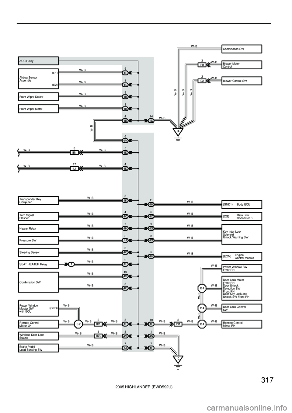
Turn Signal
Flasher
Heater Relay
Pr essure SW
Steer ing Sensor
SEAT HEATER Relay
Combination SW
Power Window
Master SW
with ECU
Remote Control
Mir ror LH Transponder Key
Computer
Body ECU
Data Link
Connector 3
Key Inter Lock
Solenoid
Remote Control
Mirror RH Door Lock Control
SW Power Window SW
Fron t RH
Door Unlock
Detection SW
Fron t RH
Wireless Door Lock
Buzzer
Br ake Pedal
Load Sensing SW4C44H11
4C6
4G9
4G8 4H7
4J6
4C3
4L9
4G10
4C5 W- B
W- B
W- B
W- B
W- B
W- B
W- B
W- BW- B
W- BW- B
W- B
W- B
B 2 I B 12
W- B
4L8
W- B
IK33
4M3
W- B
4J7 W- B
W- B4L 10 2
IN1 W- B
B 4W- B B 4 B 4
W- BW- B W- B
W- B
4N1
4L7
IC W- B
W- B(
GN D1)
(
CG)
4H5
W- B
W- B W- B
4D4
IL117
W- B W- B
4K8
W- B4D5
IE18
W- B W- B Air bag Sensor
Assembly
Front Wiper Deicer
Front Wiper Motor(
E1)
(
E2)1L9
1L1
1B9
1B8
1D14 W- B
W- B
W- B
W- B
W- B
W- B
W- B
W- B
Combination SW
Blower Motor
Control
Blower Control SW ACC Relay
IG12 W- B
W- B
W- B
IA 1E4
4M6
W- B
IH13
(
GN D)Engine
Control Module (
EOM)
1Unlock Warning SW
Door Lock Motor
Fron t RH
Door Key Lock and
Unlock SW Front RH
Page 2155 of 2572
2005 HIGHLANDER (EWD592U)
318
I GROUND POINT
Door Lock Motor
Rear RH
Power Window SW
Rear RH BC113
BC112
W- BW- B
BBW- B
W- B
Seat Heater SW RH BM11
W- BW- B
Stereo Power
Amplifier Wireless Door
Lock ECU Yaw Rate Sensor Char coal Canister
Assembly Rear Heater Blower
Motor Rear Heater Relay Rear Heater
Blower SWA
A
A
A
A
A
A
A BJ115 W- B
W- B
W- B
W- B
W- B W- B
W- B
W- B
W- B
BF
W- B
ARear Seat
Entertainment
ECU
(
SELD) (
GND)
J19
Occupant
Classification
ECU BL13
W- B W- B
W- B
W- B C
C
C
W- B
J18
C A
W- B
B A B A
A A Power Seat
Control SW
(
Front Passenger' s
Seat Contr ol)W- B
W- B W- B
(
*4)
(
*5) (
*5) (
*4) (
*4)* 4 : w/ Power Seat(
Front Passenger' s Seat)
* 5 : w/o Power Seat(
Front Passenger' s Seat)
(
E)(
GND) Door Unlock
Detection SW
Rear RH J23(
A)
, J24(
B)
Junction
Connector Junction
Connector
Junction Connector
Page 2165 of 2572
2005 HIGHLANDER (EWD592U)
8
B HOW TO USE THIS MANUAL
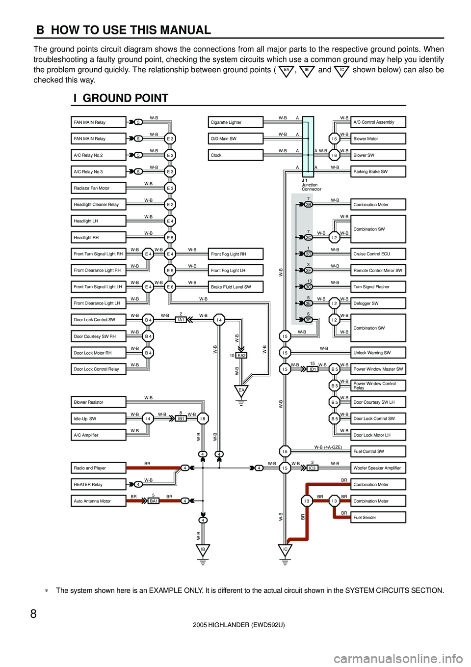
The ground points circuit diagram shows the connections from all major parts to the respective ground points. When
troubleshooting a faulty ground point, checking the system circuits which use a common ground may help you identify
the problem ground quickly. The relationship between ground points (
EA, IB and IC shown below) can also be
checked this way.
5
5
5
5
4
44
4
4 BA15IB18EA2
ID115
IC33 IA12 E 3
W-BW-B W-B W-B W-B
W-B
W-B
W-B
W-B W-B
W-B
W-B W-B
W-B
W-B W-B W-BW-B W-B W-B W-B
W-B
W-B
W-B
W-B W-B W-B
W-B
BR
W-B
BR BRW-BW-B W-B
W-B
W-B
W-B
W-B W-B W-B
W-B
W-B W-B
W-B
W-B
BR W-B
BR BR
BR W-B (4A-GZE)
W-B W-BI 2
I 2
B 5 I 5 I 5 I 5
B 5
B 5
B 5
I 5
I 5
I 3 I 3 E 3
E 3
E 3
E 2
E 4
E 5
E 4
E 5
E 6 E 4 E 4
B 4
EA I 4
B 4
B 4
I 4 I 8
IB IC 443E5
3E6 3G13 3F3 3D1 3B7W-B
W-B
W-B W-B W-B
W-B
W-B
W-B
W-B
W-B
W-B
W-B
W-B
W-B W-BI 6
I 6
I 2 3C7
10A A A A
A
A
Junction
Connector J 1
W-B
W-B
W-B W-B
BR W-B W-B
W-B
W-B W-B
W-B
I GROUND POINT
FAN MAIN Relay
FAN MAIN Relay
A/C Relay No.2
A/C Relay No.3
Radiator Fan Motor
Headlight Cleaner Relay
Headlight LH
Headlight RH
Front Fog Light LH
Brake Fluid Level SW Front Fog Light RH Front Turn Signal Light RH
Front Clearance Light RH
Front Turn Signal Light LH
Front Clearance Light LH
Door Lock Control SW
Door Courtesy SW RH
Door Lock Motor RH
Door Lock Control Relay
Blower Resistor
Idle-Up SW
A/C Amplifier
Radio and Player
HEATER Relay
Auto Antenna MotorA/C Control Assembly
Blower Motor
Blower SW
Parking Brake SW
Combination Meter
Combination SW
Cruise Control ECU
Remote Control Mirror SW
Turn Signal Flasher
Defogger SW
Unlock Warning SW
Power Window Master SW
Power Window Control
Relay
Door Courtesy SW LH
Door Lock Control SW
Door Lock Motor LH
Fuel Control SW
Woofer Speaker Amplifier
Combination Meter
Combination Meter
Fuel Sender Cigarette Lighter
O/D Main SW
Clock
Combination SW
*The system shown here is an EXAMPLE ONLY. It is different to the actual circuit shown in the SYSTEM CIRCUITS SECTION.
Page 2240 of 2572

D25085
B02389
ON 01-32
- INTRODUCTIONHOW TO TROUBLESHOOT ECU CONTROLLED
SYSTEMS
32 Author�: Date�:
2005 HIGHLANDER REPAIR MANUAL (RM1144U)
3. WATER SPRINKLING METHOD: When the malfunc-
tion seems to occur on a rainy day or in highhumidity.
(a) Sprinkle water onto the vehicle and check if the malfunc-
tion occurs.
NOTICE:
�Never sprinkle water directly into the engine compart-
ment. Indirectly change the temperature and humid-
ity by applying water spray onto the front of the radia-
tor.
�Never apply water directly onto electronic compo-
nents.
HINT:
If the vehicle has or had a water leakage problem, the leakage
may have damaged the ECU or connections. Look for evidence
of corrosion or shorts. Proceed with caution during water tests.
4. HIGH ELECTRICAL LOAD METHOD: When a malfunc-
tion seems to occur when electrical load is exces-
sive.
(a) Turn on all the electrical loads including the heater blower,
headlights, rear window defogger, etc., and check if the
malfunction occurs.
Page 2280 of 2572
2005 HIGHLANDER (EWD592U)
M
78
6 5
11 HIGHLANDER (
Cont' d)
W
Illu m in a tio n
83I
23G
W G G
10 B
5A
122
(
*5)
(
*6)(
*6) (
*5)
* 6 : 6 Speaker
A
B3H 103H 2
2 1
BW-B
3J 2
7IR1
9 10BVW-BA
A
IB Right Ins trument
Panel Br ac eBB Right
Center
PillarBF Ne ar t he Re ar
Side Marker
Light RH A
3F 13
W- B W- B W- B
* 5 : 8 Speaker * 4 : w/ Rear Heater Syst em
(
*4)(
*4)(
*4)(
*4) (
*4)
Rear Heater
Blower SW R26
Junction
Connector J19
Glov e Box Light G 4
Radio and Player R 4
Radio and Player R 2(
A)
, R 3(
B)
Page 2321 of 2572

2005 HIGHLANDER (EWD592U)
M OVERALL ELECTRICAL WIRING DIAGRAM
1
234
34 HIGHLANDER(
Cont. next page)
Power SourceA ir C onditioning (
Automatic A/C)
73
1B- YW50A
HTR
140A
ALT2I 1
40A AM17. 5A
ECU- B
2ACC
IG1 AM1 4
1C
6
1A 12A 4
10 A HEAT ER
71C
1K 13 1G82 1
5 3
4 1IK4
A A
5IL2 4H 7
4L 7
IC Right Cowl Side Panel1IH1
3IH1
IALeft Cowl Side Panel M 21 2IH117 A3A 4
3J 71G 10
1K 2 5IC3
7A 2A 12A4B2 1
16 B 15 B 3 B
1 IJ1 2 I J1 3 I J1 4 IJ1 5 IJ1 6 IJ1
1 2
M 14 B 13 B 12 B 11 B 10 B 5 B D. C. C
32
54213
41 2
B WW- B W- BBBRW- B Y- GY
B GRP O SB LG G- Y
LG- R LG- RP- LO WY
L W
W
BR
O BR Y
WB
WG
W- L
W- B
LG
LG- R
B BR
B- Y
Y
B
WP-L
W- B B
LG- R BLW AMH AMC SG- 1 S5- 1 TP TEHR IG +B S5- 3 TS SG- 3 TR
WFL MAIN
3. 0W
Bat teryYA
YA
W- L
B
Y
2 1
1 2
VM SI
GN D +B2IL2 ST1
13 A3A 13
3I 111K 31C 2 3
LL
GR VACC
7. 5A
RAD NO. 2
F 7I15
H 9 A12 R 6
J 5
A10(
A)
, A11(
B)
B 7
B 6A14
E1 2
A/C Control Assembly
A/C Solar Sensor
Air Mix Control Servo Motor
Blower MotorBlower Motor Cont rol
Evaporator Temp.
Se nso r
Fusible Link Block
Heater Relay
Ignition SW
Junction
Connec tor
Room Temp. Sensor
Page 2323 of 2572

2005 HIGHLANDER (EWD592U)
M OVERALL ELECTRICAL WIRING DIAGRAM
1
234
35 HIGHLANDER(
Cont. next page)
Power SourceAir Conditioning (
M anual A /C)
73
1B- YW50A
HEATER
140A
ALT2I 1
40A AM17. 5A
ECU- B
2ACC
IG1 AM13
4
1C
6
1A 12A 4
10 A HEAT ER
71C
1K 13 1G8
7. 5A RAD NO. 2
21C
1K 3
2 1
5 3
4 1IK4
A A
4H 7
4L 7
ICRight Cowl
Side PanelIALeft Cowl
Side Panel 1II13A 4
3J 71G 10
1K 23A 13
3I 11 5IC3
7A 2A 12A 13A
1IJ1 2IJ1 5IJ1 4IJ1 3IJ1 6IJ1
1 2
M 14B13B10B11B12B 5B D. C. C
54312 2
B WW- B W- BW- B Y- GY
B GRSBOP LG G- Y
O P- L LG- R
V
VGR
W
BR
O BR Y
WB
WGL
W- L
W- B
LG- R
B BR
B- Y
Y
B
LG- R AMH AMC T P S5 - 1 SG- 1 TE HR I G +B ACC
WFL MAIN
3. 0W
Bat teryYA
YA
W- L
L
W
Y
1IG1
1 2
M4II1 5II1 2IG1 2 II18
B- Y B BB R- BGR W- B
BR
L
R O
B
11 A
3J 6
3F 13 3J 10
6II1
IBRight Instrument
Panel Brace
W- BW- B
1
W- B
W- BGN D
LO
HI M2 M1 E
456 1
423
LG- R
AI R 1
AI F MR/FAB
W
Y
52
A 45A 6 1 2
2IL2 ST1
F 7
B 6
I15
A13 J 5
H 9
A10(
A)
, A11(
B)
B 8B 5
A14
E1 2
A/C Control AssemblyAir Inlet Control Servo Mot or
Air Mix Control Servo Mot or Blower Contr ol SW
Blower Motor
Blower Resis tor
Evaporator Temp.
Se nso r
Fu si bl e
Link Block
Heat er Relay
Ignition SW
Junction
Connec tor

