Page 631 of 1897

P. DI-212Items inside
are titles of pages in this manual,
with the page number in the bottom")
DI6N5-01
Vehicle Brought to Workshop
Customer Problem Analysis
P. DI-21 1
Check and Clear DTC (Precheck)
P. DI-212Items inside
are titles of pages in this manual,
with the page number in the bottom portion. See
the pages for detailed explanations.
Problem Symptom ConfirmationSymptom Simulation
P. IN-20
Symptom
does not occur
Symptom
occurs
DTC Check
Sensor CheckCircuit Inspection
P. DI-219 - DI-247
DTC Chart
P. DI-215 Malfunction codeProblem Symptoms Table
P. DI-218
Check for Fluid Leakage
P. DI-249
Identification of Problem
Normal code
Repair
Confirmation Test
End
1
2
3
4
5
67
89
10
11
P. DI-212
Fail safe function:
When a failure occurs in the ABS system, the ABS warning light is lit and the ABS operation is prohibited. In addition
to this, when the failure which disables the EBD operation occurs, the brake warning light is lit as well and EBD
operation is prohibited. DI-210
- DIAGNOSTICSANTI-LOCK BRAKE SYSTEM WITH ELECTRONIC
BRAKE FORCE DISTRIBUTION (EBD)
366 Author�: Date�:
2001 AVALON (RM808U)
ANTI-LOCK BRAKE SYSTEM WITH ELECTRONIC BRAKE
FORCE DISTRIBUTION (EBD)
HOW TO PROCEED WITH TROUBLESHOOTING
Troubleshoot in accordance with the procedure on the following pages.
Page 633 of 1897

DI6N7-01
F07879
F02201
E1Tc
DLC1
F00103
Normal Code
0.25 sec.
0.25 sec. 0.5 sec.
ON
OFF
ON
OFF0.5 sec. 0.5 sec.
Code 11 and 21
4 sec.1.5 sec.
2.5 sec.
Code 11 Code 21
DI-212- DIAGNOSTICSANTI-LOCK BRAKE SYSTEM WITH ELECTRONIC
BRAKE FORCE DISTRIBUTION (EBD)
368 Author�: Date�:
2001 AVALON (RM808U)
PRE-CHECK
1. DIAGNOSIS SYSTEM
(a) Release the parking brake pedal.
(b) Check the indicator.
When the ignition switch is turned ON, check that the ABS
warning light and BRAKE warning light goes on for
approx. 3 seconds.
HINT:
�When the parking brake is applied or the level of the brake
fluid is low, the BRAKE warning light is lit.
�If the indicator check result is not normal, proceed to trou-
bleshooting for the ABS warning light circuit or BRAKE
warning light circuit (See page DI-243, DI-240).
(c) Check the DTC.
(1) Using SST, connect terminals Tc and E
1 of DLC1.
SST 09843-18020
(2) Turn the ignition switch ON and read the DTC from
the ABS warning light on the combination meter.
HINT:
�If no codes appears, inspect the diagnostic circuit or ABS
warning light circuit (See page DI-245 or DI-243).
�As an example, the blinking patterns for normal code and
codes 11 and 21 are shown on the left.
(3) Codes are explained in the code table on page
DI-215.
(4) After completing the check, disconnect terminals Tc
and E
1, and turn off the display.
If 2 or more malfunction codes are identified at the
same time, the lowest numbered DTC will be dis-
played 1st.
Page 646 of 1897

F09824
Battery
FL MAIN F10 F8
F611 1
ALT
BFL BlockB-L 2G 2H1 1 Engine Room J/B B5512 AM1 Engine Room R/B No. 5 W-LIF17
W-L
2
IG1 AM1 4Ignition Switch W-R W
1C 1G
1B 1D
4
4 3 1
1
2
3 10 GAUGE No. 1 Driver Side J/B
IG1 Relay
W-B
IG
ED CUP
BRAKE
Multi DisplayM6 M3M6R-B
3 4
74D 4F13
4 J/B No. 4
R-B
L-O L-O6
IL1
R-WR-W
R-W
R-W
7
IC13A21
Active
Light
RelayR-Y 8A20
6040 74 68
32 ABS & BA &
TRAC & VSC ECU
FSS LBL PKB EBDW SP1
T5
T5
T5
T5 T5
Y-G
L-B
BR (Shielded)15
25 16
2
11
LBL LVL2PKB2BRL
PKB
Y-G Y-G
R-W
R-WJ/B No. 3
3B 3A
3A 3B 5
15
15 14
1Driver Side J/B
B1
Brake Fluid Level
Warning Switch Translate ECU
1H
1I 12
8
R-W
1 2
W-B J1 J/C
B B
W-BEngine Room J/B
44
2D2FW-B P3
Parking
Brake
SwitchA20
A20
A20
A20 DI-330
- DIAGNOSTICSABS WITH EBD & BA & TRAC & VSC SYSTEM
486 Author�: Date�:
2001 AVALON (RM808U)
BRAKE Warning Light Circuit
CIRCUIT DESCRIPTION
�The BRAKE warning light lights up when the brake fluid is insufficient, when the parking brake is ap-
plied or when the EBD is defective.
�If the translate ECU detects trouble, it makes VSC warning light lights up while prohibiting VSC & TRAC
control. At this time, the ECU records a DTC in memory. Connect terminals Tc and E
1 of the DLC1 or
DLC2 to make BRAKE warning light blink and output the DTC.
WIRING DIAGRAM
DI6OK-02
Page 647 of 1897
- DIAGNOSTICSABS WITH EBD & BA & TRAC & VSC SYSTEM
DI-331
487 Author�: Date�:
2001 AVALON (RM808U)
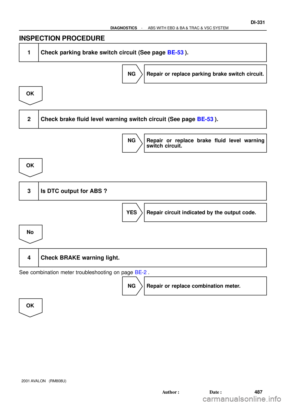
INSPECTION PROCEDURE
1 Check parking brake switch circuit (See page BE-53).
NG Repair or replace parking brake switch circuit.
OK
2 Check brake fluid level warning switch circuit (See page BE-53).
NG Repair or replace brake fluid level warning
switch circuit.
OK
3 Is DTC output for ABS ?
YES Repair circuit indicated by the output code.
No
4 Check BRAKE warning light.
See combination meter troubleshooting on page BE-2.
NG Repair or replace combination meter.
OK
Page 672 of 1897

F09814
J/B No. 3
15
3B 15
3AABS & BA & TRAC
& VSC ECU
40
A20
LBL Driver Side J/B
Engine Room J/B
M6
Multi
DisplayIC1 Translate
ECU
L-B 25
T5 11
T5
16
T5R-W
7
R-W
3
4
R-B LVL2LBL
BRL R-W
R-W
Level
Warning Switch12
1I 8
1H
R-W
12
BB J1
J/B
W-B
EDDriver Side J/B
GAUGE No. 1
W-B
W-B
J/B No. 4
10
1DR-B4
4D13
4F 4
2D4
2F
BRAKE
DI-290
- DIAGNOSTICSABS WITH EBD & BA & TRAC & VSC SYSTEM
446 Author�: Date�:
2001 AVALON (RM808U)
DTC C1202 / 44 Brake Fluid Level Warning Switch Cir-
cuit
CIRCUIT DESCRIPTION
The brake fluid level warning switch sends appropriate signals to the ECU when the brake fluid level is low-
ered.
HINT:
Depressing the parking brake pedal turns on the brake warning light, but this DTC No. C1202/44 is not out-
put.
DTC No.DTC Detecting ConditionTrouble Area
C1202 / 44
Fluid level in the brake master cylinder reservoir tank re-
mains low for 60 sec. or more. This means brake fluid
warning switch likes on.�Brake fluid level
�Brake fluid level warning switch
�Brake fluid level warning switch circuit
WIRING DIAGRAM
DI6O3-01
Page 673 of 1897
- DIAGNOSTICSABS WITH EBD & BA & TRAC & VSC SYSTEM
DI-291
447 Author�: Date�:
2001 AVALON (RM808U)
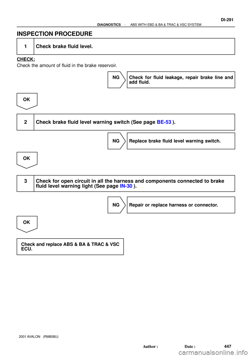
INSPECTION PROCEDURE
1 Check brake fluid level.
CHECK:
Check the amount of fluid in the brake reservoir.
NG Check for fluid leakage, repair brake line and
add fluid.
OK
2 Check brake fluid level warning switch (See page BE-53).
NG Replace brake fluid level warning switch.
OK
3 Check for open circuit in all the harness and components connected to brake
fluid level warning light (See page IN-30).
NG Repair or replace harness or connector.
OK
Check and replace ABS & BA & TRAC & VSC
ECU.
Page 683 of 1897

INSPECTION PROCEDURE
HINT:
Start the inspection from step 1, in case of using the TOYO")
F07902
PMCE2
- DIAGNOSTICSABS WITH EBD & BA & TRAC & VSC SYSTEM
DI-301
457 Author�: Date�:
2001 AVALON (RM808U)
INSPECTION PROCEDURE
HINT:
Start the inspection from step 1, in case of using the TOYOTA hand-held tester and start from step 2, in case
of not using the TOYOTA hand-held tester.
1 Check output value of the master cylinder pressure sensor.
PREPARATION:
(a) Connect the TOYOTA hand-held tester to the DLC3.
(b) Turn the ignition switch ON and push the TOYOTA hand-held tester main switch ON.
(c) Select the DATALIST mode on the TOYOTA hand-held tester.
CHECK:
Check that the brake fluid pressure value of the master cylinder pressure sensor displayed on the TOYOTA
hand-held tester is changing when depressing the brake pedal.
OK:
Brake fluid pressure value must be changing.
OK Go to step 4.
NG
2 Check master cylinder pressure sensor.
PREPARATION:
Install LSPV gauge to the front caliper bleeder plug portion, and
bleed the air from LSPV gauge.
SST 09709-29018
CHECK:
Start the engine and depress the brake pedal, then check the
relation between the fluid pressure and voltage of PMC and E2
terminals of the master cylinder pressure sensor with connector
still connected.
OK:
Front brake caliper fluid pressureVoltage
0 kPa (0 Kgf/cm2, 0 psi)0.44 - 0.76 V
5,883 kPa (60 kgf/cm2, 853 psi)1.34 - 1.66 V
11,768 kPa (120 kgf/cm2, 1,706 psi)2.24 - 2.56 V
HINT:
Voltage between terminals VCM and E2: 4.7 - 5.3 V
NG Replace master cylinder pressure sensor.
OK
Page 701 of 1897

DTC Normal Code Malfunction in ECM
CIRCUIT DESCRIPTION
If any trouble occurs in the ECM control sys")
- DIAGNOSTICSABS WITH EBD & BA & TRAC & VSC SYSTEM
DI-317
473 Author�: Date�:
2001 AVALON (RM808U)
DTC Normal Code Malfunction in ECM
CIRCUIT DESCRIPTION
If any trouble occurs in the ECM control system, the ECU prohibits ABS & VSC control.
DTC No.DTC Detecting ConditionTrouble Area
Normal Code
Conditions 1., 2,. 3, or 4,continue for 5 sec. or more:
1. Engine malfunction signal is sent from ECM.
2. Shift malfunction signal is sent from ECM
3. The shift position is other than P and N range input volt-
age is 8 V or more.
4. The shift position is PN or rev and D range input voltage
is 8 V or more.�ECM circuit
�ECM
�Brake fluid level
�Brake fluid level warning switch circuit
�Steering angle sensor
�ABS & BA & TRAC & VSC ECU
INSPECTION PROCEDURE
1 Is DTC out put for ECM?
Check DTC on page DI-3.
YES Repair engine control system according to the
output code.
NO
2 Check the DTC for the ABS and VSC (See page DI-252).
*1 Repair ABS and VSC control system according
to the code output.
*2
Check and replace translate ECU.
*1: Output NG code except for DTC of VSC system C1301/42
*2: Output NG code DTC of VSC system C1301/42 only
DI6OF-03