Page 50 of 801

YH4
GRAND
VITARA
1. ªUPPERº or ªLOWERº mark
MAINTENANCE AND LUBRICATION 0B-23
3) Visually check pump drive belt for cracks and wear.
4) Check belt for tension, referring to item 1-1.
If necessary, have belt adjusted or replaced.
ITEM 6-16
All Hinges, Latches and Locks Inspection
Doors
Check that each door of front, rear and back doors opens and
closes smoothly and locks securely when closed.
If any malfunction is found, lubricate hinge and latch or repair door
lock system.
Engine hood
Check that secondary latch operates properly (check that second-
ary latch keeps hood from opening all the way even when pulling
hood release handle inside vehicle.). Also check that hood opens
and closes smoothly and properly and hood locks securely when
closed.
If any malfunction is found, lubricate hinge and latch, or repair hood
lock system.
ITEM 6-17
Air Conditioning Filter (if equipped)
Inspection
1) Remove air conditioning filter from cooling unit referring to Sec-
tion 1B.
2) Check filter for dirt. Replace excessively dirty filter.
3) Blow off dust by compressed air from air outlet side of filter.
4) Install filter to cooling unit referring to Section 1B.
Replacement
Replace air conditioning filter with new one referring to Section 1B.
Page 312 of 801
YH4
GRAND
VITARA
5A-18 BRAKES PIPE / HOSE / MASTER CYLINDER
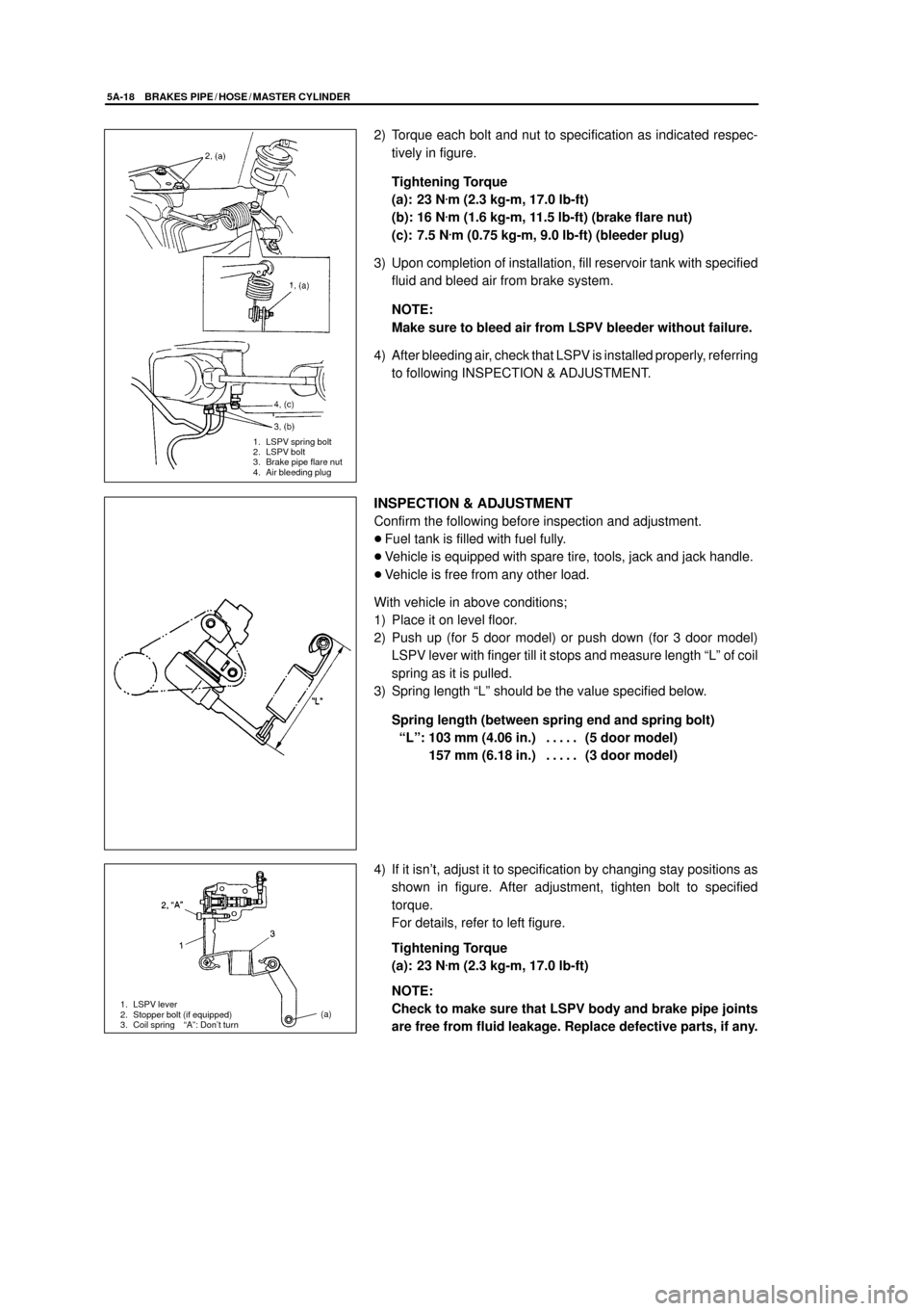
1. LSPV spring bolt
2. LSPV bolt
3. Brake pipe flare nut
4. Air bleeding plug
1. LSPV lever
2. Stopper bolt (if equipped)
3. Coil spring ªAº: Don't turn(a)
2) Torque each bolt and nut to specification as indicated respec-
tively in figure.
Tightening Torque
(a): 23 N
.m (2.3 kg-m, 17.0 lb-ft)
(b): 16 N
.m (1.6 kg-m, 11.5 lb-ft) (brake flare nut)
(c): 7.5 N
.m (0.75 kg-m, 9.0 lb-ft) (bleeder plug)
3) Upon completion of installation, fill reservoir tank with specified
fluid and bleed air from brake system.
NOTE:
Make sure to bleed air from LSPV bleeder without failure.
4) After bleeding air, check that LSPV is installed properly, referring
to following INSPECTION & ADJUSTMENT.
INSPECTION & ADJUSTMENT
Confirm the following before inspection and adjustment.
�Fuel tank is filled with fuel fully.
�Vehicle is equipped with spare tire, tools, jack and jack handle.
�Vehicle is free from any other load.
With vehicle in above conditions;
1) Place it on level floor.
2) Push up (for 5 door model) or push down (for 3 door model)
LSPV lever with finger till it stops and measure length ªLº of coil
spring as it is pulled.
3) Spring length ªLº should be the value specified below.
Spring length (between spring end and spring bolt)
ªLº: 103 mm (4.06 in.) (5 door model). . . . .
ªLº: 157 mm (6.18 in.) (3 door model). . . . .
4) If it isn't, adjust it to specification by changing stay positions as
shown in figure. After adjustment, tighten bolt to specified
torque.
For details, refer to left figure.
Tightening Torque
(a): 23 N
.m (2.3 kg-m, 17.0 lb-ft)
NOTE:
Check to make sure that LSPV body and brake pipe joints
are free from fluid leakage. Replace defective parts, if any.
Page 620 of 801
YH4
GRAND
VITARA
6. Door trim
7. Door hinge
8. Door open stop
9. Door sealing cover
10. Window regulator handle (if equipped) 1. Door glass
2. Weatherstrip
3. Opening weatherstrip
4. Window regulator
5. Glass run
9-2 BODY SERVICE
GLASS, WINDOWS AND MIRROR
FRONT DOOR GLASS
Page 621 of 801

YH4
GRAND
VITARA
1. Screws 1. Door outside weatherstrip
2. Screw1. Door inside pull handle bracket
BODY SERVICE 9-3
REMOVAL
1) Remove inside handle bezel.
2) Remove door mirror bezel (if equipped).
3) Remove inside lock knob and door inside pull handle case fitting
screw.
3-1) Remove window regulator handle (if equipped).
To remove regulator handle, pull off snap ring by using a cloth
as shown below.
4) Remove door trim.
With inside handle bezel tilted as shown in figure, turn door trim
90� counterclockwise to remove it.
And disconnect power window switch lead wire at coupler (if
equipped).
5) Remove door inside pull handle bracket.
6) Remove door sealing cover.
7) Remove door outside weatherstrip.
Lower window all the way down. Then, use a tape-wrapped putty
knife (or screwdriver) to pry off weatherstrip.
CAUTION:
Use a tape-wrapped putty knife (or screwdriver) to pry off
weatherstrip. Use of an unwrapped tool will cause dam-
age to painting.
8) Remove glass attaching screws.
9) Take out door glass.
Page 623 of 801

YH4
GRAND
VITARA
1. Window regulator lubrication point 1. Regulator mounting bolts
2. Regulator motor mounting nuts
3. Hole
BODY SERVICE 9-5
FRONT DOOR WINDOW REGULATOR
REMOVAL
1) Remove door glass, referring to steps 1) to 9) of FRONT DOOR
GLASS REMOVAL in this section.
2) Disconnect power window motor lead wire at coupler and loosen
clamp.
3) Loosen regulator mounting bolts, nuts and take out regulator
through hole as shown in left figure.
INSPECTION
1) Check regulator sliding and rotating parts for greasing.
2) Check rollers for wear and damage.
3) Check wire for damage.
INSTALLATION
Reverse removal procedure to install window regulator noting the
following point.
�Tighten bolts and nuts according to the order (a, b, c / 1, 2, 3, 4)
shown in left figure.
�When installing glass, check that the top part of the glass contacts
the glass run evenly and that the glass moves up and down
smoothly.
If the glass is tilted with respect to the glass run, make a fine ad-
justment with the screws.
�Install door window regulator handle (if equipped) so that it has
an angle as shown in figure when glass is fully closed.
Page 630 of 801
YH4
GRAND
VITARA
1. Door trim
2. Inside handle
bezel7. Door hinge
8. Door open stop
9. Door sealing cover
10. Door center sash
11. Partition glass
12. Window regulator handle (if equipped) 1. Door glass
2. Weatherstrip (outside)
3. Glass run
4. Window regulator
5. Partition weather strip
6. Door trim
9-12 BODY SERVICE
REAR DOOR GLASS
REMOVAL
-1) Remove inside handle bezel.
-2) Remove inside lock knob and door inside pull handle case fit-
ting screw.
2-1) Window regulator handle (if equipped).
To remove regulator handle, pull off snap ring by using a cloth
as shown below.
3) Remove door trim with inside weatherstrip.
With inside handle bezel tilted as shown in figure, turn door trim
90� counterclockwise to remove it. And disconnect power win-
dow switch lead wire.
4) Remove door sealing cover.
Page 632 of 801

YH4
GRAND
VITARA
9-14 BODY SERVICE
1. Door window
regulator attaching
nuts
2. Hole
1. Window regulator lubrication points
1. Door sealing
cover
2. Adhesive
REAR DOOR WINDOW REGULATOR
REMOVAL
1) Remove door glass, refer to steps 1) to 10) of REAR DOOR
GLASS REMOVAL in this section.
2) Disconnect power window motor lead wire at coupler and clamp.
3) Remove door window regulator attaching nuts (6 pcs.), and take
out regulator through hole as shown in left figure.
INSPECTION
1) Check regulator sliding and rotating parts for greasing.
2) Check rollers for wear and damage.
3) Check wire for damage.
INSTALLATION
Reverse removal sequence to install door window regulator noting
following points.
�Tighten regulator base nuts according to the order (a, b, c) shown
in figure.
�Adjust door window regulator according to following procedure.
a. Loosen three nuts, two screws and two bolts.
b. Raise window fully.
c. Tighten three regulator rail nuts according to the order (d, e,
f) shown in figure and two center sash bolts A.
d. Lower window.
e. Tighten two screws B to specified torque. Tighten front screw
first, then rear.
Tightening Torque for glass attaching screws
2.5 N
.m (0.25 kg-m, 1.8 lb-ft)
f. Check that the glass moves up and down smoothly and that
the top part of the glass contacts the glass run evenly.
�Securely seal door sealing cover with adhesive.
�Install door window regulator handle (if equipped) so that it has
an angle as shown when glass is fully closed.
Page 637 of 801

YH4
GRAND
VITARA
BODY SERVICE 9-19
1. Back door panel assy
2. Back door window glass
3. Back door hinge
4. Back door / Rear gate balancer unit
1. Back door hinge
2. Back door
3. Body
BACK DOOR / REAR GATE ASSEMBLY
REMOVAL
1) Remove back door trim, and door / rear gate sealing cover, refer
to steps 1) to 4) of BACK DOOR LOCK ASSEMBLY in this sec-
tion.
2) Remove wire harness connector inside the back door / rear gate.
3) Remove back door / rear gate balancer (first at its door-side and
next at its body-side), as shown.
WARNING:
Handling of Back Door / Rear Gate Balancer (Damper)
�Do not disassemble balancer because its cylinder is
filled with gas.
�The gas itself is harmless but it may issue out of the
hole together with chips generated by the drill.
Therefore, be sure to wear goggle.
�When discarding removed back door / rear gate balanc-
er (damper), use a 2 to 3 mm (0.08 to 0.12 in.) drill to
make a hole as shown.
�Handle balancer carefully. Do not scar or scratch ex-
posed surface of its piston rod, and never allow any
paint or oil to stick to its surface.
�Do not turn piston rod with balancer fully extended.
5) Remove back door / rear gate hinge bolts and back door / rear
gate.

