Page 504 of 656

DIFFERENTIAL (REAR) 7F-19
7) Measure preload of pinion bearing with spring balance (1) or
torque wrench (2) and check composite preload of pinion
bearing and side bearing.
Composite preload of pinion bearing and side bearing
: 1.1 – 2.0 N·m (11.0 – 20.0 kg-cm, 9.5 – 17.4 lb-in.)
Spring measure reading with special tool
: 19.5 – 35.5 N (1.95 – 3.55 kg, 4.30 – 7.83 lb)
Special tool
(D) : 09922-76560
8) Torque bearing cap bolts (2) to specification and install bear-
ing lock plates.
Tightening torque
Lock plate bolt (b) : 12 N·m (1.2 kg-m, 9.0 lb-ft)
Bearing cap bolt (c) : 85 N·m (8.5 kg-m, 61.5 lb-ft)
9) As final step, check gear tooth contact as follows.
a) After cleaning 10 drive bevel gear teeth, paint them with
gear marking compound evenly by using brush or sponge
etc.
b) Turn gear to bring its painted part in mesh with drive bevel
pinion and turn it back and forth by hand to repeat their con-
tact.
c) Bring painted part up and check contact pattern, referring
to following chart. If contact pattern is not normal, readjust
or replace as necessary according to instruction in chart. NOTE:
Before taking measurement with spring balance (1) or
torque wrench (2), check for smooth rotation by hand.
On measuring preload, rotate the drive bevel pinion
about 1 rotation per 2 seconds.
3. Universal joint flange
4. Socket with adapter
1. Lock plate bolt
NOTE:
Be careful not to turn drive bevel gear more than one full
revolution, for it will hinder accurate check.
1. Brush
“A”: Paint gear marking compound evenly
Page 522 of 656

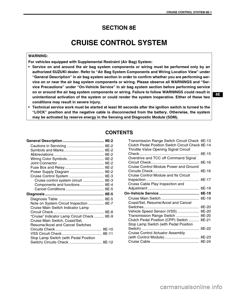
CRUISE CONTROL SYSTEM 8E-1
6F1
6F2
6G
6H
6K
7A
7A1
7B1
7C1
7D
7E
8E
8A
8B
8C
8D
8B
9
10
10A
10B
SECTION 8E
CRUISE CONTROL SYSTEM
CONTENTS
General Description ....................................... 8E-2
Cautions in Servicing ................................... 8E-2
Symbols and Marks ...................................... 8E-2
Abbreviations ............................................... 8E-2
Wiring Color Symbols ................................... 8E-2
Joint Connector ............................................ 8E-2
Fuse Box and Relay ..................................... 8E-2
Power Supply Diagram ................................ 8E-2
Cruise Control System ................................. 8E-3
Cruise control system circuit .................... 8E-3
Components and functions....................... 8E-4
Cancel Conditions .................................... 8E-5
Diagnosis ........................................................ 8E-5
Diagnosis Table ........................................... 8E-5
Note on System Circuit Inspection ............... 8E-7
Cruise Main Switch Indicator Lamp
Circuit Check ................................................ 8E-8
“Cruise” Indicator Lamp Circuit Check ......... 8E-9
Cruise Main Switch, Coast/Set,
Resume/Accel and Cancel Switches
Circuits Check ............................................ 8E-10
VSS Circuit Check ...................................... 8E-11
Stop Lamp Switch (with Pedal Position
Switch) Circuits Check ............................... 8E-12Transmission Range Switch Circuit Check 8E-13
Clutch Pedal Position Switch Circuit Check 8E-14
Throttle Valve Opening Signal Circuit
Check ......................................................... 8E-15
Overdrive and TCC off Command Signal
Circuit Check.............................................. 8E-16
Cruise Control Module Power and Ground
Circuits Check ............................................ 8E-16
Cruise Control Module and Its Circuit
Inspection................................................... 8E-17
Cruise Cable Play Inspection and
Adjustment ................................................. 8E-19
On-Vehicle Service ...................................... 8E-19
Cruise Main Switch .................................... 8E-19
Coast/Set, Resume/Accel and Cancel
Switches..................................................... 8E-20
Vehicle Speed Sensor (VSS) ..................... 8E-20
Transmission Range Switch ...................... 8E-20
Clutch Pedal Position (CPP) Switch .......... 8E-21
Stop Lamp Switch (with Pedal Position
Switch) ....................................................... 8E-22
Cruise Control Actuator Assembly
(with Control Module) ................................. 8E-23
Cruise Cable .............................................. 8E-24
WARNING:
For vehicles equipped with Supplemental Restraint (Air Bag) System:
Service on and around the air bag system components or wiring must be performed only by an
authorized SUZUKI dealer. Refer to “Air Bag System Components and Wiring Location View” under
“General Description” in air bag system section in order to confirm whether you are performing ser-
vice on or near the air bag system components or wiring. Please observe all WARNINGS and “Ser-
vice Precautions” under “On-Vehicle Service” in air bag system section before performing service
on or around the air bag system components or wiring. Failure to follow WARNINGS could result in
unintentional activation of the system or could render the system inoperative. Either of these two
conditions may result in severe injury.
Technical service work must be started at least 90 seconds after the ignition switch is turned to the
“LOCK” position and the negative cable is disconnected from the battery. Otherwise, the system
may be activated by reserve energy in the Sensing and Diagnostic Module (SDM).
Page 523 of 656
8E-2 CRUISE CONTROL SYSTEM
General Description
Cautions in Servicing
Refer to Section 8.
Symbols and Marks
Refer to Section 8A.
Abbreviations
Refer to Section 8A.
Wiring Color Symbols
Refer to Section 8.
Joint Connector
Refer to Section 8.
Fuse Box and Relay
Refer to Section 8A.
Power Supply Diagram
Refer to Section 8A.
Page 634 of 656

AIR BAG SYSTEM 10B-57
Accident with or without deployment/activation - component inspections
Certain air bag and restraint system components must be inspected after any crash, whether the air bag system
activated or not.
Those components are:
•Steering column and shaft joints
–Check for length, damage and bend according to “CHECK-
ING STEERING COLUMN FOR ACCIDENT DAMAGE” in
Section 3C1.
•Steering column bracket and capsules
–Check for damage and bent.
•If any faulty condition is found in above checks, replace faulty
part.
•Steering wheel and driver air bag (inflator) module
–Check for damage or air bag (inflator) module fitness.
–Check trim cover (pad surface) for cracks.
–Check wire harness and connector for damage or tightness.
•If any faulty condition is found in above checks, replace faulty
part.
•Contact coil and combination switch assembly
–Check wire harness and connectors for damage or tight-
ness.
–Check contact coil case for damage.
•If any faulty condition is found in above checks, replace.