Page 581 of 656
10B-4 AIR BAG SYSTEM
System Components and Wiring Location View and Connectors
1. Air bag harness 7. Passenger air bag (inflator) module 13. Grommet
2.“AIR BAG” fuse box 8. SDM 14. Instrument panel harness
3.“AIR BAG” monitor coupler 9. Seat belt pretensioner (retractor assembly) (if equipped) 15. Main harness
4. DLC 10. Pretensioner harness 16. Forward sensor
5. Contact coil assembly 11. Ground for air bag system
6. Driver air bag (inflator) module 12. Connector “G03”, “E12”
16 16
15
13
12
14
1113
10 15 5
6
3
248
9 1 7 15
9
10
CONNECTOR “Q06”CONNECTOR “Q05”CONNECTOR “G27”CONNECTOR “Q02”
CONNECTOR “Q07”
CONNECTOR “Q11”
CONNECTOR “Q03” CONNECTOR “Q12”CONNECTOR “Q01”
Page 582 of 656

AIR BAG SYSTEM 10B-5
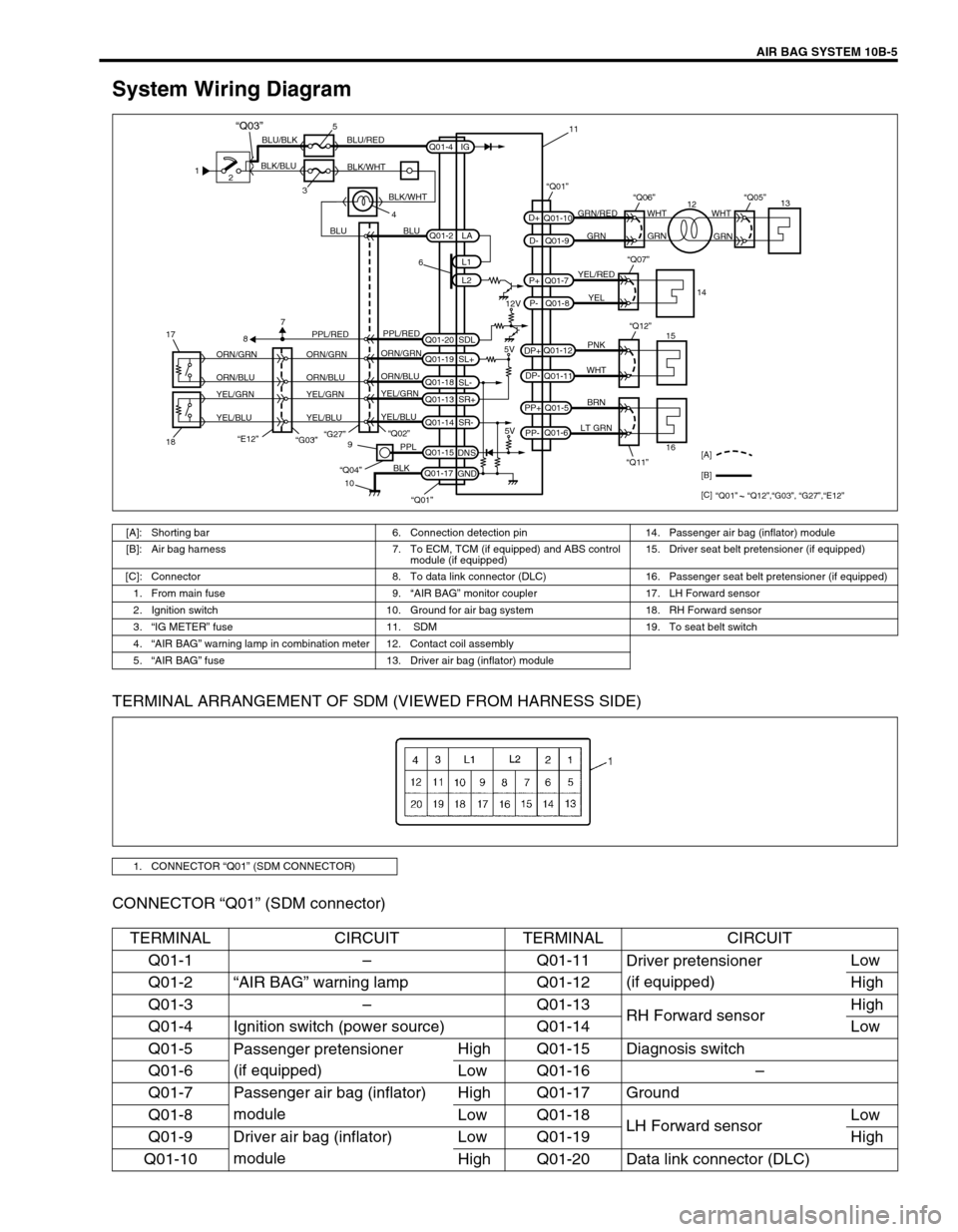
System Wiring Diagram
TERMINAL ARRANGEMENT OF SDM (VIEWED FROM HARNESS SIDE)
CONNECTOR “Q01” (SDM connector)
1
2
35
4 BLK/BLUBLU/BLK BLU/RED
BLK/WHT
BLU BLUGRN/RED
GRN GRNWHT WHT
GRN
YEL/RED
YEL
PNK
WHT
BRN
LT GRN
6
12V
5V 5V PPL/RED
ORN/GRN
ORN/BLU
YEL/GRN
YEL/BLUORN/GRN
ORN/BLU
YEL/GRN
YEL/BLUORN/GRN
ORN/BLU
YEL/GRN
YEL/BLUPPL/RED
87
“G27”
“E12”18 17“Q02”
“Q11” “Q12”9
10PPL
BLK
“Q04”
Q01-2
Q01-4
Q01-20Q01-7
Q01-8 Q01-10
Q01-9
Q01-12
Q01-11
Q01-5
Q01-6
Q01-15
Q01-17L1
L2 IG
SDL
Q01-19
SL+
Q01-18
SL-
Q01-13
SR+
Q01-14
SR-
DNS
GNDLA
PP- PP+DP- DP+P- P+D- D+
“Q07”
“Q06”“Q01”“Q05”
15
161413
12 11
[A]
[B]
[C]
“Q01” “Q12”,“G03”, “G27”,“E12”
“Q01”
BLK/WHT
“Q03”
“G03”
[A]: Shorting bar 6. Connection detection pin 14. Passenger air bag (inflator) module
[B]: Air bag harness 7. To ECM, TCM (if equipped) and ABS control
module (if equipped) 15. Driver seat belt pretensioner (if equipped)
[C]: Connector 8. To data link connector (DLC) 16. Passenger seat belt pretensioner (if equipped)
1. From main fuse 9.“AIR BAG” monitor coupler 17. LH Forward sensor
2. Ignition switch 10. Ground for air bag system 18. RH Forward sensor
3.“IG METER” fuse 11. SDM 19. To seat belt switch
4.“AIR BAG” warning lamp in combination meter 12. Contact coil assembly
5.“AIR BAG” fuse 13. Driver air bag (inflator) module
1. CONNECTOR “Q01” (SDM CONNECTOR)
TERMINAL CIRCUIT TERMINAL CIRCUIT
Q01-1–Q01-11
Driver pretensioner
(if equipped)Low
Q01-2“AIR BAG” warning lamp Q01-12 High
Q01-3–Q01-13
RH Forward sensorHigh
Q01-4 Ignition switch (power source) Q01-14 Low
Q01-5
Passenger pretensioner
(if equipped)High Q01-15 Diagnosis switch
Q01-6 Low Q01-16–
Q01-7 Passenger air bag (inflator)
moduleHigh Q01-17 Ground
Q01-8 Low Q01-18
LH Forward sensorLow
Q01-9 Driver air bag (inflator)
moduleLow Q01-19 High
Q01-10 High Q01-20 Data link connector (DLC)
Page 584 of 656

AIR BAG SYSTEM 10B-7
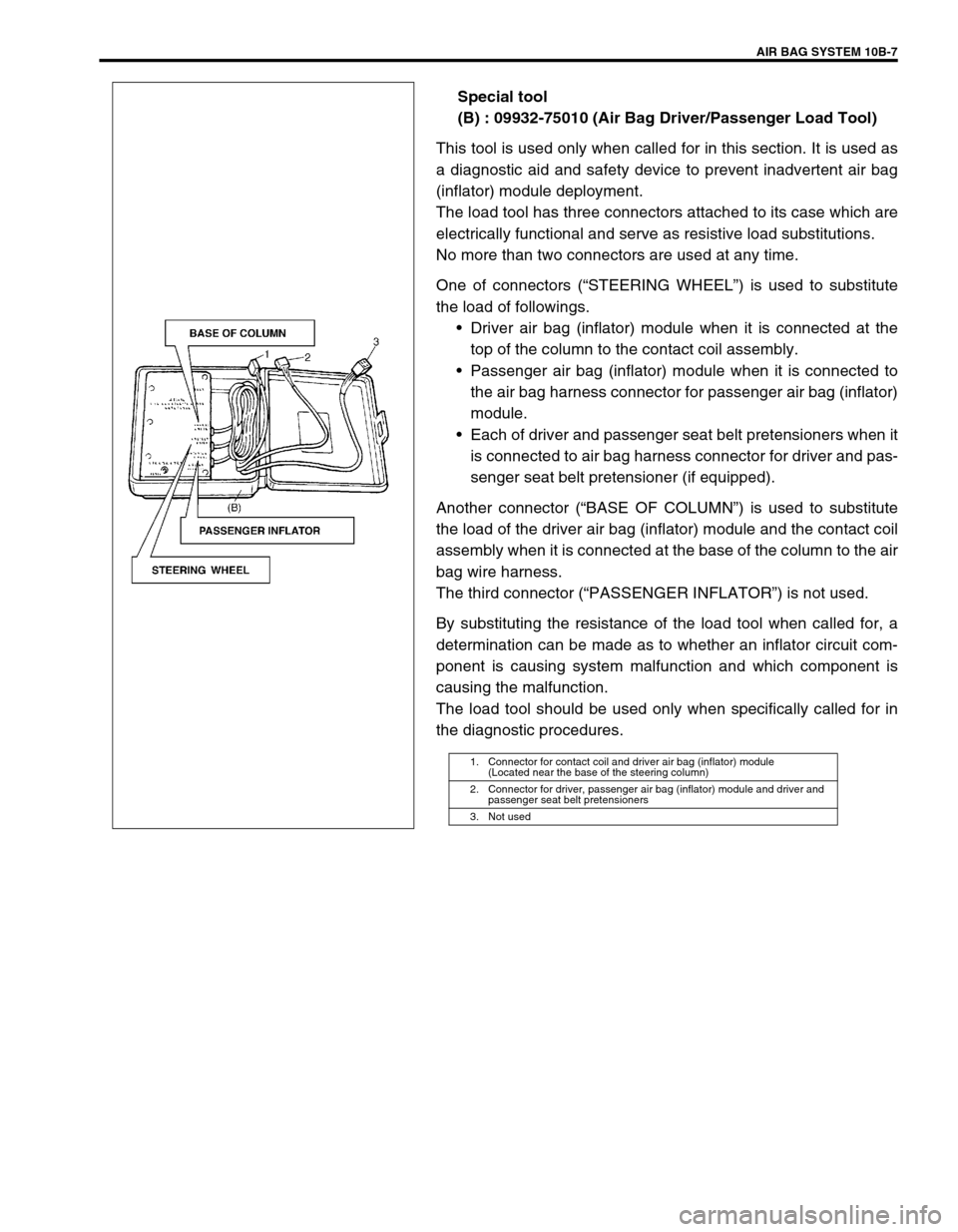
Special tool
(B) : 09932-75010 (Air Bag Driver/Passenger Load Tool)
This tool is used only when called for in this section. It is used as
a diagnostic aid and safety device to prevent inadvertent air bag
(inflator) module deployment.
The load tool has three connectors attached to its case which are
electrically functional and serve as resistive load substitutions.
No more than two connectors are used at any time.
One of connectors (“STEERING WHEEL”) is used to substitute
the load of followings.
•Driver air bag (inflator) module when it is connected at the
top of the column to the contact coil assembly.
•Passenger air bag (inflator) module when it is connected to
the air bag harness connector for passenger air bag (inflator)
module.
•Each of driver and passenger seat belt pretensioners when it
is connected to air bag harness connector for driver and pas-
senger seat belt pretensioner (if equipped).
Another connector (“BASE OF COLUMN”) is used to substitute
the load of the driver air bag (inflator) module and the contact coil
assembly when it is connected at the base of the column to the air
bag wire harness.
The third connector (“PASSENGER INFLATOR”) is not used.
By substituting the resistance of the load tool when called for, a
determination can be made as to whether an inflator circuit com-
ponent is causing system malfunction and which component is
causing the malfunction.
The load tool should be used only when specifically called for in
the diagnostic procedures.
1. Connector for contact coil and driver air bag (inflator) module
(Located near the base of the steering column)
2. Connector for driver, passenger air bag (inflator) module and driver and
passenger seat belt pretensioners
3. Not used
Page 617 of 656

10B-40 AIR BAG SYSTEM
DTC B1041 – Driver Pretensioner Initiator Circuit Resistance High
DTC B1042 – Driver Pretensioner Initiator Circuit Resistance Low
DTC B1043 – Driver Pretensioner Initiator Circuit Short to Ground
DTC B1044 – Driver Pretensioner Initiator Circuit Short to Power Circuit
DTC B1045 – Passenger Pretensioner Initiator Circuit Resistance High
DTC B1046 – Passenger Pretensioner Initiator Circuit Resistance Low
DTC B1047 – Passenger Pretensioner Initiator Circuit Short to Ground
DTC B1048 – Passenger Pretensioner Initiator Circuit Short to Power Circuit
WIRING DIAGRAM
[A] : Shorting bar 2. Ignition switch 5. Driver seat belt pretensioner
[B] : Air bag harness 3.“AIR BAG” fuse 6. Passenger seat belt pretensioner
1. From main fuse 4. SDM 7. Ground for air bag system
PNK
WHT
BRN
LT GRN
“Q11” “Q12”
Q01-12
Q01-11
Q01-5
Q01-6 PP- PP+ DP- DP+
“Q01”
5
6 [A]
[B]1
2BLU/BLK
BLU/RED
3
7
BLK
“Q01” Q01-4
Q01-17IG
GND4
CAUTION:
Be sure to perform AIR BAG DIAGNOSTIC SYSTEM CHECK before starting diagnosis according to
flow table.
When measurement of resistance or voltage is required in this table, use a tester along with a cor-
rect terminal adapter from special tool (Connector test adapter kit).
When a check for proper connection is required, refer to INTERMITTENT AND POOR CONNEC-
TIONS in this section.
If there is open circuit in the air bag wire harness, connector or terminal is found damaged, replace
the wire harness, connector and terminal as an assembly.
Page 618 of 656

AIR BAG SYSTEM 10B-41
DTC WILL SET WHEN
DTC B1041 and B1045 :
The resistance of driver or passenger seat belt pretensioner initiator circuit is above a specified value for speci-
fied time.
DTC B1042 and B1046 :
The resistance of driver or passenger seat belt pretensioner initiator circuit is below a specified value for speci-
fied time.
DTC B1043 and B1047 :
The voltage measured at driver or passenger seat belt pretensioner initiator circuit is below a specified value for
specified time.
DTC B1044 and B1048 :
The voltage measured at driver or passenger seat belt pretensioner initiator circuit is above a specified value for
specified time.
TABLE TEST DESCRIPTION
DTC B1041, B1042, B1043, B1044, B1045, B1046, B1047 and B1048 :
STEP 1 : Check whether malfunction is in seat belt pretensioner.
STEP 2 : Check seat belt pretensioner initiator circuit in air bag harness.
DIAGNOSTIC FLOW TABLE
DTC B1041 and B1045 :
Step Action Yes No
1 1) With ignition switch OFF, remove center
pillar inner garnish of applicable side then
disconnect seat belt pretensioner connec-
tor.
2) Check proper connection to applicable
seat belt pretensioner at terminals in
“Q11” or “Q12” connector.
3) If OK then connect Special Tool (B) to
seat belt pretensioner connector discon-
nected at the step 1.
With ignition switch ON, is DTC B1041 or
B1045 still current?Go to step 2. Ignition switch OFF.
Replace seat belt preten-
sioner (Refer to Section
10A).
2 1) With ignition switch OFF, disconnect SDM
connector.
2) Check proper connection to SDM at termi-
nals “Q01-11” and “Q01-12” or “Q01-6”
and “Q01-5”.
3) If OK then measure resistance between
“Q01-11” and “Q01-12” terminals or “Q01-
6” and “Q01-5” terminals with connected
Special Tool (B).
Is resistance 4.5 Ω or less?Substitute a known-
good SDM and recheck.DTC B1041 :
Repair high resistance or
open in “PNK” or “WHT” wire
circuit.
DTC B1045 :
Repair high resistance or
open in “BRN” or “LT GRN”
wire circuit.
Page 619 of 656
![SUZUKI GRAND VITARA 2001 2.G Owners Manual 10B-42 AIR BAG SYSTEM
Fig. for STEP 1 and 2
Fig. for STEP 2
Special tool
(A) : 09932-75020
(B) : 09932-75010
DTC B1042 and B1046 :
1. Pretensioner harness
[A] : For DTC B1041
[B] : For DTC B1045
NOTE SUZUKI GRAND VITARA 2001 2.G Owners Manual 10B-42 AIR BAG SYSTEM
Fig. for STEP 1 and 2
Fig. for STEP 2
Special tool
(A) : 09932-75020
(B) : 09932-75010
DTC B1042 and B1046 :
1. Pretensioner harness
[A] : For DTC B1041
[B] : For DTC B1045
NOTE](/manual-img/20/7584/w960_7584-618.png)
10B-42 AIR BAG SYSTEM
Fig. for STEP 1 and 2
Fig. for STEP 2
Special tool
(A) : 09932-75020
(B) : 09932-75010
DTC B1042 and B1046 :
1. Pretensioner harness
[A] : For DTC B1041
[B] : For DTC B1045
NOTE:
Upon completion of inspection and repair work, perform following items.
Reconnect all air bag system components, ensure all components are properly mounted.
Clear diagnostic trouble codes (Refer to DTC CLEARANCE), if any.
Repeat AIR BAG DIAGNOSTIC SYSTEM CHECK to confirm that the trouble has been corrected.
Step Action Yes No
1 1) With ignition switch OFF, remove center pil-
lar inner garnish of applicable side then dis-
connect seat belt pretensioner connector.
2) Check proper connection to applicable seat
belt pretensioner at terminals in “Q11” or
“Q12” connector.
3) If OK then connect Special Tool (B) to seat
belt pretensioner connector disconnected at
the step 1.
With ignition switch ON, is DTC B1042 or
B1046 still current?Go to step 2. Ignition switch OFF.
Replace seat belt preten-
sioner (Refer to Section
10A).
Page 621 of 656

10B-44 AIR BAG SYSTEM
DTC B1043 and B1047 :
Fig. for STEP 1 and 2
Fig. for STEP 2
Special tool
(A) : 09932-75020
(B) : 09932-75010 Step Action Yes No
1 1) With ignition switch OFF, remove center pil-
lar inner garnish of applicable side then dis-
connect seat belt pretensioner connector.
2) Check proper connection to applicable seat
belt pretensioner at terminals in “Q11” or
“Q12” connector.
3) If OK then connect Special Tool (B) to seat
belt pretensioner connector disconnected at
the step 1.
With ignition switch ON, is DTC B1043 or
B1047 still current?Go to step 2. Ignition switch OFF.
Replace seat belt pretensioner
(Refer to Section 10A).
2 1) With ignition switch OFF, disconnect Spe-
cial Tool (B) and SDM.
2) Measure resistance between “Q01-11” or
“Q01-6” and body ground.
Is circuit open?Substitute a
known-good SDM
and recheck.DTC B1043 :
Repair short “PNK” or “WHT” wire
circuit to ground.
DTC B1047 :
Repair short from “BRN” or “LT
GRN” wire circuit to ground.
1. Pretensioner harness
[A] : For DTC B1043
[B] : For DTC B1047
Page 622 of 656

AIR BAG SYSTEM 10B-45
DTC B1044 and B1048 :
Fig. for STEP 1 and 2NOTE:
Upon completion of inspection and repair work, perform following items.
Reconnect all air bag system components, ensure all components are properly mounted.
Clear diagnostic trouble codes (Refer to DTC CLEARANCE), if any.
Repeat AIR BAG DIAGNOSTIC SYSTEM CHECK to confirm that the trouble has been corrected.
Step Action Yes No
1 1) With ignition switch OFF, remove center
pillar inner garnish of applicable side then
disconnect seat belt pretensioner connec-
tor.
2) Check proper connection to applicable
seat belt pretensioner at terminals in
“Q11” or “Q12” connector.
3) If OK then connect Special Tool (B) to
seat belt pretensioner connector discon-
nected at the step 1.
With ignition switch ON, is DTC B1044 or
B1048 still current?Go to step 2. Ignition switch OFF.
Replace seat belt preten-
sioner (Refer to Section
10A).
2 1) With ignition switch OFF, disconnect Spe-
cial Tool (B) and SDM.
2) Measure voltage from “Q01-12” or “Q01-
5” terminal to body ground.
With ignition switch ON, is voltage 1 V or
less?Substitute a known-
good SDM and recheck.DTC B1044 :
Repair short “PNK” or “WHT”
wire circuit to power circuit.
DTC B1048 :
Repair short from “BRN” or
“LT GRN” wire circuit to
power circuit.
1. Pretensioner harness