2001 SUZUKI GRAND VITARA oil pressure
[x] Cancel search: oil pressurePage 449 of 656

7B1-40 AUTOMATIC TRANSMISSION (4 A/T)
TROUBLESHOOTING
Road Test
This test is to check if upshift and downshift take place at specified speed while actually driving vehicle on a
level road.
1) Warm up engine.
2) With engine running at idle, shift select lever “D”.
3) Accelerate vehicle speed by depressing accelerator pedal gradually.
4) While driving in “D” range, check if gear shift occurs properly as shown in “GEAR SHIFT DIAGRAM” in this
section.
TROUBLESHOOTING
Condition Possible cause
Line pressure higher than standard level in each
range•Malfunctioning regulator valve
•Malfunctioning throttle valve
•Maladjusted A/T throttle cable
Line pressure lower than standard level in each
range•Defective O/D clutch
•Defective oil pump
•Malfunctioning throttle valve
•Malfunctioning regulator value
•Maladjusted A/T throttle cable
Line pressure lower than standard level only in
“D” range•Fluid leakage from forward clutch
•Defective O/D clutch
•Leakage from “D” range fluid pressure circuit
Line pressure lower than standard level only in
“R” range•Fluid leakage from direct clutch
•Defective O/D clutch
•Fluid leakage from reverse brake
•Fluid leakage from “R” range fluid circuit
WARNING:
Carry out test in very little traffic area to prevent an accident.
Test requires 2 persons, a driver and a tester.
Condition Possible cause
When 1 → 2 upshift fails to occur 1–2 shift valve stuck
When 2 → 3 upshift fails to occur 2–3 shift valve stuck
When 3 → O/D upshift fails to occur 3–4 shift valve stuck
When gear shift point is incorrect•Maladjusted throttle cable
•Defective shift solenoid valve -A or -B
•1–2, 2–3 or 3–4 shift valve not operating properly
Page 463 of 656

7B1-54 AUTOMATIC TRANSMISSION (4 A/T)
6) Install direct clutch cylinder to center support.
Remove direct clutch piston by blowing air into the second
hole from the left as shown in the figure. Also, remove direct
clutch inner piston by blowing air into hole at the extreme
right. And then remove O-rings from pistons.
Front upper valve body
ASSEMBLY
Assemble each component by reversing disassembly procedure
and noting the following points.
•Coil outer diameter and free length of each valve spring
should be as listed below. Be sure to use each one of correct
size.
Coil outer diameter and free length of each valve spring
•Install as many throttle valve compensating rings as written
down when disassembled.
•Tighten throttle cam bolt (1) to specified torque.
Tightening torque
Throttle cam bolt (a) : 7.5 N·m (0.75 kg-m, 5.5 lb-ft)
•Tighten pressure relief valve bolts (1) to specified torque.
Tightening torque
Pressure relief valve bolt (b) : 5.5 N·m (0.55 kg-m, 4.0 lb-ft)
Name of spring Outer diameter Free length
Secondary regulator
valve spring17.43 mm
(0.681 in.)71.27 mm
(2.806 in.)
Cut back valve spring 6.85 mm
(0.259 in.)23.0 mm
(0.906 in.)
Throttle valve
secondary spring8.56 mm
(0.337 in.)18.86 mm
(0.743 in.)
Throttle valve
primary spring10.90 mm
(0.429 in.)39.55 mm
(1.557 in.)
Page 467 of 656

7B1-58 AUTOMATIC TRANSMISSION (4 A/T)
ASSEMBLY
Assemble each component by reversing disassembly procedure
and noting the following points.
•Coil outer diameter and free length of each valve spring
should be as listed below. Be sure to use each one of correct
size.
Coil outer diameter and free length of each valve spring :
•Install primary regulator valve sleeve so that its tip is posi-
tioned as it was before disassembly.
•Use new TCC (lock-up) control valve gasket, solenoid gas-
ket and lower valve body plate gasket.
•Tighten shift solenoid valve bolt to specified torque.
Tightening torque
Shift solenoid valve bolt : 10 N·m (1.0 kg-m, 7.5 lb-ft)
Name of spring Outer diameter Free length
Pressure relief valve spring 13.14 mm (0.517 in.) 32.14 mm (1.265 in.)
TCC (Lock-up) control valve
spring11.40 mm (0.449 in.) 32.60 mm (1.283 in.)
Valve damping spring 4.95 mm (0.195 in.) 20.00 mm (0.787 in.)
Low coast modulator valve spring 10.00 mm (0.394 in.) 42.35 mm (1.667 in.)
Inter coast modulator valve
spring9.04 mm (0.356 in.)
(G16 and J20 engines)27.26 mm (1.073 in.)
(G16 and J20 engines)
10.00 mm (0.394 in.)
(H25 and H27 engine)25.60 mm (1.008 in.)
(H25 and H27 engine)
Ball valve spring 10.5 mm (0.413 in.) 13.7 mm (0.539 in.)
Bypass valve spring 13.82 mm (0.544 in.) 28.90 mm (1.138 in.)
Primary regulator valve spring 17.02 mm (0.670 in.) 50.28 mm (1.980 in.)
1. Solenoid valve No. 1 (Shift solenoid valve)
2. Low coast modulator valve spring
3. Inter coast modulator valve spring
4. Intermediate coast modulator valve
5. Low coast modulator valve
Page 470 of 656

AUTOMATIC TRANSMISSION (4 A/T) 7B1-61
Special Tool
09925-37811-001 09931-76030 09931-76011
Oil pressure gauge 16/14 pin DLC cable for
Tech 1AMass storage cartridge for
Tech 1ATech 1A kit (SUZUKI scan
tool) (See NOTE “A”.)
09940-53111
Bearing installer Tech 2 kit (SUZUKI scan
tool) (See NOTE “B”.)
NOTE:
“A”: This kit includes the following items and substitutes for the Tech 2 kit.
1. Storage case, 2. Operator’s manual, 3. Suzuki scan tool, 4. DLC cable, 5. Test lead/probe,
6. Power source cable, 7. DLC cable adapter, 8. Self-test adapter
“B”: This kit includes the following items and substitutes for the Tech 1A kit.
1. Tech 2, 2. PCMCIA card, 3. DLC cable, 4. SAE 16/19 adapter, 5. Cigarette cable, 6. DLC loopback
adapter, 7. Battery power cable, 8. RS232 cable, 9. RS232 adapter, 10. RS232 loopback connector,
11. Storage case, 12. Power supply
Page 487 of 656

7F-2 DIFFERENTIAL (REAR)
General Description
The differential assembly using a hypoid bevel pinion and gear is installed to the rear axle. It is set in the conven-
tional type axle housing.
The differential assembly is decisive in that the drive power is concentrated there. Therefore, use of genuine
parts and specified torque is compulsory. Further, because of sliding tooth meshing with high pressure between
bevel pinion and gear, it is mandatory to lubricate them by hypoid gear oil.
Diagnosis
Diagnosis Table
Condition Possible Cause Correction
Gear noiseDeteriorated or water mixed lubricant Repair and replenish.
Inadequate or insufficient lubricant Repair and replenish.
Maladjusted backlash between drive bevel pin-
ion and gearAdjust as prescribed.
Improper tooth contact in the mesh between
drive bevel pinion and gearAdjust or replace.
Loose drive bevel gear securing bolts Replace or retighten.
Damaged differential gear(s) or differential pin-
ion(s)Replace.
Bearing noise(Constant noise) Deteriorated or water mixed
lubricantRepair and replenish.
(Constant noise) Inadequate or insufficient
lubricantRepair and replenish.
(Noise while coasting) Damaged bearing(s) of
drive bevel pinionReplace.
(Noise while turning) Damaged differential side
bearing(s) or axle bearing(s)Replace.
Oil leakageClogged breather plug Clean.
Worn or damaged oil seal Replace.
Excessive oil Adjust oil level.
Page 512 of 656

INSTRUMENTATION/DRIVER INFORMATION 8C-1
8C
SECTION 8C
INSTRUMENTATION/DRIVER INFORMATION
CONTENTS
General Description ........................................8C-2
Combination Meter ........................................8C-2
On-vehicle Service ..........................................8C-4
Fuel Meter/Fuel Gauge Unit ..........................8C-4
Fuel level sensor (sender gauge) ..............8C-4
Engine Coolant Temperature (ECT) Meter
and Sensor ....................................................8C-5Engine coolant temperature sensor .......... 8C-5
Oil Pressure Light ......................................... 8C-5
Oil pressure switch .................................... 8C-5
Brake Warning Light ..................................... 8C-5
Brake fluid level switch .............................. 8C-5
WARNING:
For vehicles equipped with Supplemental Restraint (Air Bag) System:
Service on and around the air bag system components or wiring must be performed only by an
authorized SUZUKI dealer. Refer to “Air Bag System Components and Wiring Location View” under
“General Description” in air bag system section in order to confirm whether you are performing ser-
vice on or near the air bag system components or wiring. Please observe all WARNINGS and “Ser-
vice Precautions” under “On-Vehicle Service” in air bag system section before performing service
on or around the air bag system components or wiring. Failure to follow WARNINGS could result in
unintentional activation of the system or could render the system inoperative. Either of these two
conditions may result in severe injury.
Technical service work must be started at least 90 seconds after the ignition switch is turned to the
“LOCK” position and the negative cable is disconnected from the battery. Otherwise, the system
may be activated by reserve energy in the Sensing and Diagnostic Module (SDM).
NOTE:
For the descriptions (items) not found in this section, refer to the same section of the Service Manual
mentioned in the FOREWORD of this manual.
Page 513 of 656

8C-2 INSTRUMENTATION/DRIVER INFORMATION
General Description
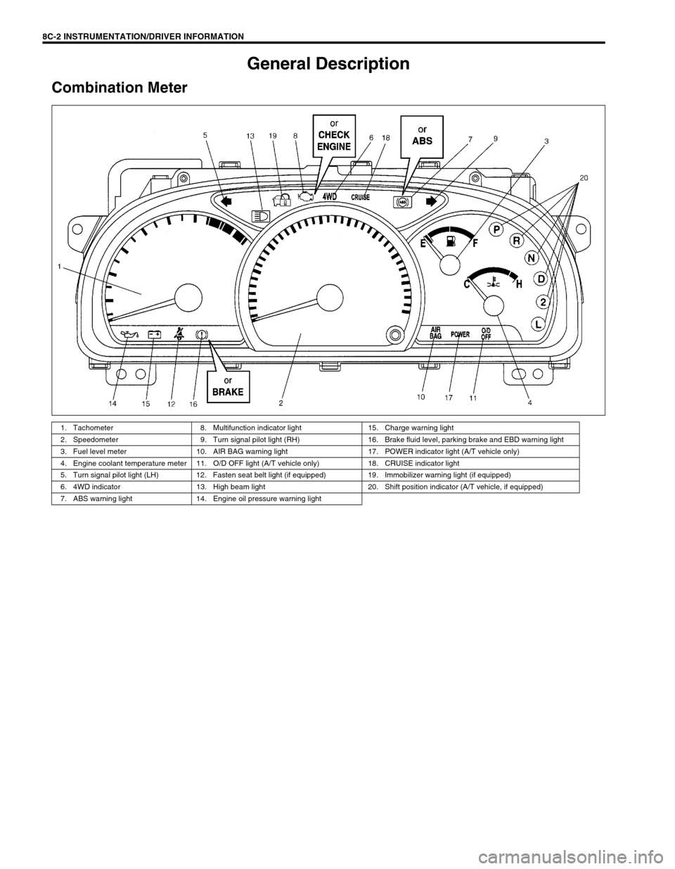
Combination Meter
1. Tachometer 8. Multifunction indicator light 15. Charge warning light
2. Speedometer 9. Turn signal pilot light (RH) 16. Brake fluid level, parking brake and EBD warning light
3. Fuel level meter 10. AIR BAG warning light 17. POWER indicator light (A/T vehicle only)
4. Engine coolant temperature meter 11. O/D OFF light (A/T vehicle only) 18. CRUISE indicator light
5. Turn signal pilot light (LH) 12. Fasten seat belt light (if equipped) 19. Immobilizer warning light (if equipped)
6. 4WD indicator 13. High beam light 20. Shift position indicator (A/T vehicle, if equipped)
7. ABS warning light 14. Engine oil pressure warning light
Page 514 of 656
![SUZUKI GRAND VITARA 2001 2.G Owners Manual INSTRUMENTATION/DRIVER INFORMATION 8C-3
COMBINATION METER INTERNAL CIRCUITS
COMBINATION METER COUPLERS
[A] : Coupler A [B] : Coupler B [C] : Coupler C
1. To Cruise control module (if equipped) GRY/YE SUZUKI GRAND VITARA 2001 2.G Owners Manual INSTRUMENTATION/DRIVER INFORMATION 8C-3
COMBINATION METER INTERNAL CIRCUITS
COMBINATION METER COUPLERS
[A] : Coupler A [B] : Coupler B [C] : Coupler C
1. To Cruise control module (if equipped) GRY/YE](/manual-img/20/7584/w960_7584-513.png)
INSTRUMENTATION/DRIVER INFORMATION 8C-3
COMBINATION METER INTERNAL CIRCUITS
COMBINATION METER COUPLERS
[A] : Coupler A [B] : Coupler B [C] : Coupler C
1. To Cruise control module (if equipped) GRY/YEL 1. To door switch (drive side) BLK/BLU 1. To ground BLK
2. Blank–2. To transmission range switch
(A/T vehicle only, if equipped) LGRN/BLU 2. To ECM (PCM for A/T vehicle) BRN
3. To ignition switch BLK/WHT 3. To transmission range switch
(A/T vehicle only, if equipped) 2GRN/ORN 3. To ignition switch PPL/RED
4. Blank–4. To transmission range switch
(A/T vehicle only, if equipped) DYEL/GRN 4. To brake fluid level switch RED/BLK
5. To ABS control module (if equipped) BLU/ORN 5. To transmission range switch
(A/T vehicle only, if equipped) NORN/BLU 5. To parking brake switch PPL
6. To PCM (A/T vehicle only) GRY/BLU 6. To transmission range switch
(A/T vehicle only, if equipped) PORN/GRN 6. To seat belt switch GRY/RED
7. To ABS control module (if equipped) BRN 7. To transmission range switch
(A/T vehicle only, if equipped) RRED 7. To generator WHT/RED
8. To VSS BLU/YEL 8. To illumination control module RED/GRN 8. To engine oil pressure switch YEL/BLK
9. To combination switch GRN/RED 9. To PCM (A/T vehicle only) WHT/BLK 9. To combination switch RED/YEL
10. To air bag SDM BLU 10. To ECT sensor YEL/WHT 10. To ignition switch BLU/RED
11. To main fuse WHT/BLU 11. To fuel level gauge BLU/WHT
12. To fuse box WHT 12. To ground BLU/YEL
13. To combination switch RED 13. To combination switch GRN/YEL
14. To immobilizer control module
(if equipped)PPL
15. To ECM (PCM for A/T vehicle) PPL/YEL
16. To ECM (PCM for A/T vehicle) ORN/BLK
P R N D 2 LCRUISEPOWER4WDSPEED
METERTACHO
METERFUEL
METERTEMP.
METER
A-11
A-13 A-8 B-12 B-11 C-8 A-15 A-6 A-1 B-9 A-16 A-14 C-7 C-1 A-10 C-3 C-4 C-5 A-7 A-5 B-8 B-1B-10 C-2 A-12 A-3B-13 B-2 B-3 B-4 B-5 B- B-6 C-9 C-10 A-9ABS circuit EBD circuit Air bag circuit
or ABS or BRAKE
if equipped
or CHECK
ENGINE
NOTE:
Terminal arrangement of coupler viewed from harness side.