2001 SUZUKI GRAND VITARA ECT sensor
[x] Cancel search: ECT sensorPage 532 of 656

CRUISE CONTROL SYSTEM 8E-11
VSS Circuit Check
Fig. for Step 1Step Action Yes No
1 Vehicle Speed Sensor Circuit Check
1) Disconnect connector from cruise control module with
ignition switch OFF.
2) Check for proper connection to cruise control module at
terminal E132-1.
3) If OK, check for continuity between terminals E132-1 and
E59-2, terminals C52-2 and C20-1 referring to “CRUISE
CONTROL SYSTEM” in Section 8A.
Is check result satisfactory?VSS circuit is OK.“BLU/YEL” cir-
cuit is open.
Page 536 of 656

CRUISE CONTROL SYSTEM 8E-15
Throttle Valve Opening Signal Circuit Check
Fig. for Step 2Step Action Yes No
1 Powertrain Control Module (PCM) Diagnostic Trouble Code
Check
1) Check PCM for DTC.
Is there a DTC related to throttle position sensor?Check and repair
TP sensor refer-
ring to Section 6-1.Go to Step 2.
2 Throttle Valve Opening Signal Circuit Check
1) Turn ignition switch ON.
2) Check voltage between terminal E61-4 of PCM connector
connected and ground.
Does voltage vary linearly according to throttle opening?Throttle valve
opening signal cir-
cuit is OK.Go to Step 3.
3 Supply Voltage Check
1) Disconnect connector from PCM with ignition switch OFF.
2) Check for proper connection to PCM at terminal E61-4.
3) If OK, connect “BLU” wire terminal of main relay to ground
with service wire.
4) Turn ignition switch ON.
5) Check voltage between E61-4 of PCM connector and
ground.
Is it 10 – 14 V?Check TP sensor
and circuits refer-
ring to Section 6-1.
If OK, substitute a
known-good PCM
and recheck.Check “GRY”
wire for open
and short. If OK,
proceed to
cruise control
module power
and ground cir-
cuits check.
Page 538 of 656

CRUISE CONTROL SYSTEM 8E-17
Cruise Control Module and Its Circuit Inspection
VOLTAGE CHECK
Check for input or output voltage of control module (voltage between each circuit and body ground) with cruise
control module connector connected.CAUTION:
Cruise control module can not be checked by itself. It is strictly prohibited to connect voltmeter or
ohmmeter to cruise control module with coupler disconnected from it.
CIRCUIT NORMAL
VOLTAGECONDITION
Vehicle speed sensor Indicator deflection
repeated between
0 – 1 V and 3 – 5 VIgnition switch ON and cruise main switch ON. Vehicle
hoisted and rear left tire turned slowly with rear right
tire locked.
Stop lamp switch 0 – 2 V Brake pedal released.
10 – 14 V Brake pedal depressed.
Overdrive and TCC off signal
(4 A/T only) 10 – 14 V Ignition switch ON.
CRUISE indicator light 10 – 14 V Ignition switch ON.
Ground––
Brake pedal position switch
(in stop lamp switch) 10 – 14 V Ignition switch ON and brake pedal released.
0 V Ignition switch ON and brake pedal depressed.
Throttle valve opening signal
from PCM (4A/T only)Ignition switch ON.
Voltage varies as specified by graph in “THROTTLE VALVE OPENING SIG-
NAL CIRCUIT CHECK” in this section.
Cruise main switch 7 – 9V Ignition switch ON and cruise main switch released.
3 – 5 V Ignition switch ON and cruise main switch pressed.
CANCEL switch 0 – 1 V Ignition switch ON and CANCEL switch pressed.
COAST SET switch 1 – 2 V Ignition switch ON and COAST SET switch rotated.
RESUME ACCEL switch 2.5 – 4 V Ignition switch ON and RESUME ACCEL switch
rotated.
Clutch pedal position switch
(M/T only)10 – 14 V Ignition switch ON and clutch pedal released.
0 – 1 V Ignition switch ON and clutch pedal depressed fully.
Transmission range switch
(Park/Neutral position switch)
(A/T only)0 V Ignition switch ON and selector lever in “P” or “N”
range.
10 – 14 V Ignition switch ON and selector lever in “R”, “D”, “2” or
“L” range.
Cruise main switch indicator
lamp0 – 1 V Ignition switch ON.
10 – 14 V Ignition switch ON and after input main switch ON sig-
nal.
Page 541 of 656

8E-20 CRUISE CONTROL SYSTEM
Coast/Set, Resume/Accel and Cancel
Switches
These switches are built in the combination switch assembly.
REMOVAL AND INSTALLATION
Refer to “COMBINATION SWITCH” in Section 3C1.
INSPECTION
1) Disable air bag system referring to “DISABLING AIR BAG
SYSTEM” in Section 10B.
2) Disconnect connector (1) of COAST/SET, RESUME/ACCEL
and CANCEL switches.
3) Check for resistance between “SW” and “GND” terminals of
disconnected switch connector (1) under each condition
below.
If check result is not satisfactory, replace combination switch
assembly.
COAST/SET, RESUME/ACCEL and CANSEL switch speci-
fication
All switches released (OFF) : Infinity
CANCEL switch pressed (ON) : About 0 Ω
ΩΩ Ω
COAST/SET switch rotated (ON) : 200 – 240 Ω
ΩΩ Ω
RESUME/ACCEL switch rotated (ON) : 820 – 1000 Ω
ΩΩ Ω
Vehicle Speed Sensor (VSS)
INSPECTION
Refer to Section 6E2.
Transmission Range Switch
Refer to Section 7B1 for inspection, removal, installation and
adjustment.CAUTION:
Never disassemble combination switch assembly. Disas-
sembly will spoil its original functions.
Page 579 of 656

10B-2 AIR BAG SYSTEM
DTC B1031 – Power Source Voltage
High........................................................... 10B-33
DTC B1032 – Power Source Voltage
Low ........................................................... 10B-33
DTC B1035 – RH Forward Sensor Circuit
Open or Short to Ground .......................... 10B-36
DTC B1036 – RH Forward Sensor Circuit
Short Between Two Wires or Short to
Power Circuit............................................. 10B-36
DTC B1037 – LH Forward Sensor Circuit
Open or Short to Ground .......................... 10B-36
DTC B1038 – LH Forward Sensor Circuit
Short Between Two Wires or Short to
Power Circuit............................................. 10B-36
DTC B1041 – Driver Pretensioner Initiator
Circuit Resistance High............................. 10B-40
DTC B1042 – Driver Pretensioner Initiator
Circuit Resistance Low ............................. 10B-40
DTC B1043 – Driver Pretensioner Initiator
Circuit Short to Ground ............................. 10B-40
DTC B1044 – Driver Pretensioner Initiator
Circuit Short to Power Circuit .................... 10B-40
DTC B1045 – Passenger Pretensioner
Initiator Circuit Resistance High ................ 10B-40
DTC B1046 – Passenger Pretensioner
Initiator Circuit Resistance Low................. 10B-40
DTC B1047 – Passenger Pretensioner
Initiator Circuit Short to Ground ................ 10B-40
DTC B1048 – Passenger Pretensioner
Initiator Circuit Short to Power Circuit ....... 10B-40
DTC B1051 – Frontal Crash Detected
(System Activation Command Outputted). 10B-46DTC B1061 – “AIR BAG” Warning Lamp
Circuit Failure............................................ 10B-47
DTC B1071 – Internal SDM Fault ............. 10B-48
DTC B1013 – System Specifications
Different from SDM Specifications ............ 10B-48
On-Vehicle Service ..................................... 10B-49
Service Precautions .................................. 10B-49
Service and diagnosis ........................... 10B-49
Disabling air bag system ....................... 10B-50
Enabling air bag system........................ 10B-50
Handling and storage ............................ 10B-51
Repairs and Inspections Required after
an Accident ............................................... 10B-56
Accident with deployment/activation -
component replacement ....................... 10B-56
Accident with or without deployment/
activation - component inspections....... 10B-57
SDM .......................................................... 10B-60
Forward Sensor ........................................ 10B-62
Seat Belt Pretensioner .............................. 10B-64
Air Bag (Inflator) Module and Seat Belt
Pretensioner Disposal................................ 10B-65
Deployment/Activation Outside Vehicle .... 10B-66
Deployment/Activation Inside Vehicle....... 10B-72
Deployed Air Bag (Inflator) Module and
Activated Seat Belt Pretensioner
Disposal .................................................... 10B-76
Tightening Torque Specification............... 10B-77
Special Tool ................................................ 10B-77
Page 581 of 656

10B-4 AIR BAG SYSTEM
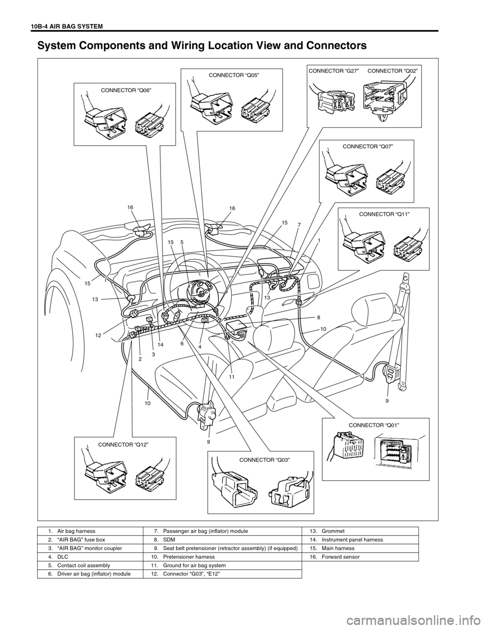
System Components and Wiring Location View and Connectors
1. Air bag harness 7. Passenger air bag (inflator) module 13. Grommet
2.“AIR BAG” fuse box 8. SDM 14. Instrument panel harness
3.“AIR BAG” monitor coupler 9. Seat belt pretensioner (retractor assembly) (if equipped) 15. Main harness
4. DLC 10. Pretensioner harness 16. Forward sensor
5. Contact coil assembly 11. Ground for air bag system
6. Driver air bag (inflator) module 12. Connector “G03”, “E12”
16 16
15
13
12
14
1113
10 15 5
6
3
248
9 1 7 15
9
10
CONNECTOR “Q06”CONNECTOR “Q05”CONNECTOR “G27”CONNECTOR “Q02”
CONNECTOR “Q07”
CONNECTOR “Q11”
CONNECTOR “Q03” CONNECTOR “Q12”CONNECTOR “Q01”
Page 582 of 656

AIR BAG SYSTEM 10B-5
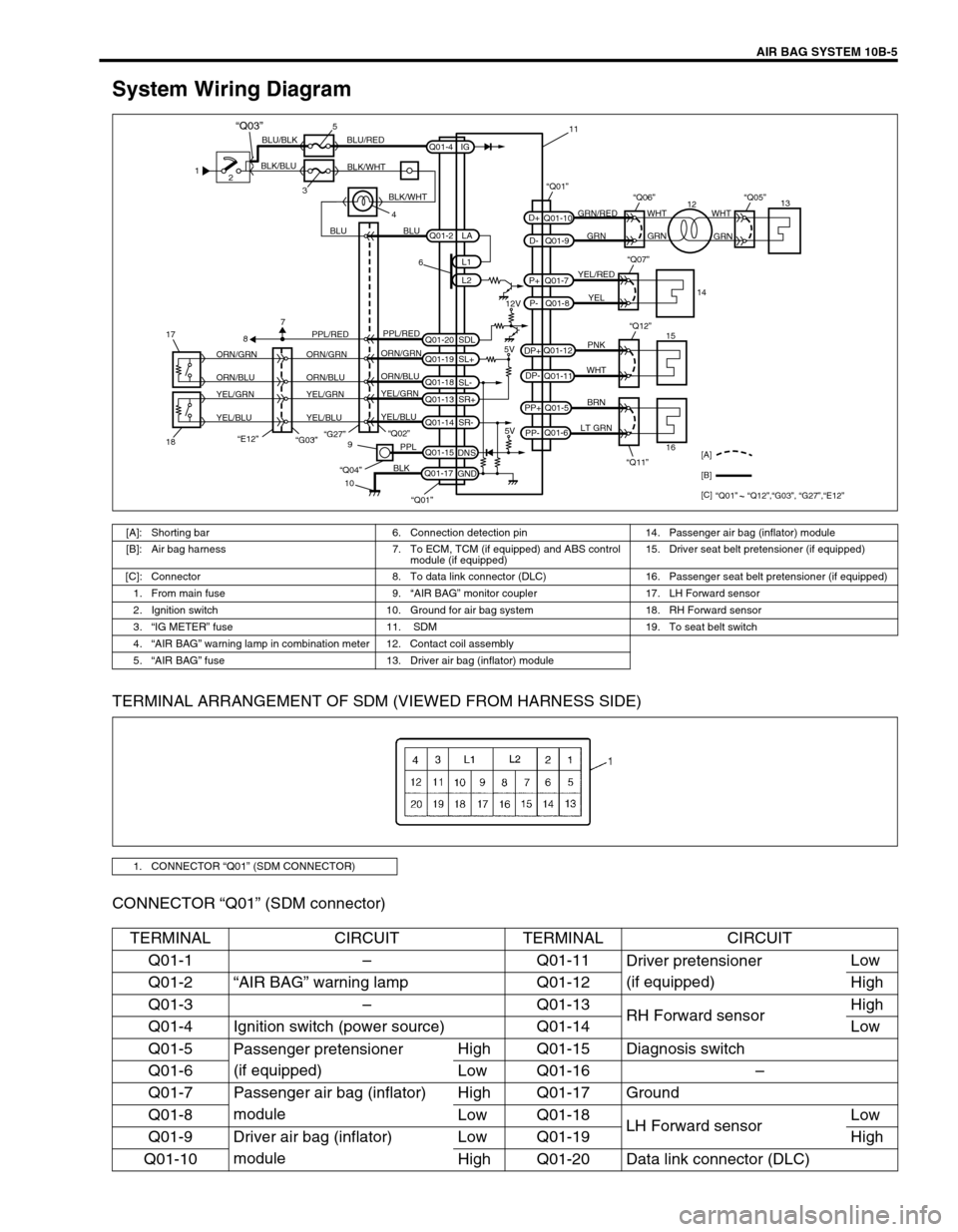
System Wiring Diagram
TERMINAL ARRANGEMENT OF SDM (VIEWED FROM HARNESS SIDE)
CONNECTOR “Q01” (SDM connector)
1
2
35
4 BLK/BLUBLU/BLK BLU/RED
BLK/WHT
BLU BLUGRN/RED
GRN GRNWHT WHT
GRN
YEL/RED
YEL
PNK
WHT
BRN
LT GRN
6
12V
5V 5V PPL/RED
ORN/GRN
ORN/BLU
YEL/GRN
YEL/BLUORN/GRN
ORN/BLU
YEL/GRN
YEL/BLUORN/GRN
ORN/BLU
YEL/GRN
YEL/BLUPPL/RED
87
“G27”
“E12”18 17“Q02”
“Q11” “Q12”9
10PPL
BLK
“Q04”
Q01-2
Q01-4
Q01-20Q01-7
Q01-8 Q01-10
Q01-9
Q01-12
Q01-11
Q01-5
Q01-6
Q01-15
Q01-17L1
L2 IG
SDL
Q01-19
SL+
Q01-18
SL-
Q01-13
SR+
Q01-14
SR-
DNS
GNDLA
PP- PP+DP- DP+P- P+D- D+
“Q07”
“Q06”“Q01”“Q05”
15
161413
12 11
[A]
[B]
[C]
“Q01” “Q12”,“G03”, “G27”,“E12”
“Q01”
BLK/WHT
“Q03”
“G03”
[A]: Shorting bar 6. Connection detection pin 14. Passenger air bag (inflator) module
[B]: Air bag harness 7. To ECM, TCM (if equipped) and ABS control
module (if equipped) 15. Driver seat belt pretensioner (if equipped)
[C]: Connector 8. To data link connector (DLC) 16. Passenger seat belt pretensioner (if equipped)
1. From main fuse 9.“AIR BAG” monitor coupler 17. LH Forward sensor
2. Ignition switch 10. Ground for air bag system 18. RH Forward sensor
3.“IG METER” fuse 11. SDM 19. To seat belt switch
4.“AIR BAG” warning lamp in combination meter 12. Contact coil assembly
5.“AIR BAG” fuse 13. Driver air bag (inflator) module
1. CONNECTOR “Q01” (SDM CONNECTOR)
TERMINAL CIRCUIT TERMINAL CIRCUIT
Q01-1–Q01-11
Driver pretensioner
(if equipped)Low
Q01-2“AIR BAG” warning lamp Q01-12 High
Q01-3–Q01-13
RH Forward sensorHigh
Q01-4 Ignition switch (power source) Q01-14 Low
Q01-5
Passenger pretensioner
(if equipped)High Q01-15 Diagnosis switch
Q01-6 Low Q01-16–
Q01-7 Passenger air bag (inflator)
moduleHigh Q01-17 Ground
Q01-8 Low Q01-18
LH Forward sensorLow
Q01-9 Driver air bag (inflator)
moduleLow Q01-19 High
Q01-10 High Q01-20 Data link connector (DLC)
Page 613 of 656

10B-36 AIR BAG SYSTEM
DTC B1035 – RH Forward Sensor Circuit Open or Short to Ground
DTC B1036 – RH Forward Sensor Circuit Short Between Two Wires or Short to
Power Circuit
DTC B1037 – LH Forward Sensor Circuit Open or Short to Ground
DTC B1038 – LH Forward Sensor Circuit Short Between Two Wires or Short to
Power Circuit
WIRING DIAGRAM
DTC WILL SET WHEN
DTC B1035 and B0137 :
The voltage measured at forward sensor circuit (terminal Q01-18, Q01-14) is below a specified value for speci-
fied time.
DTC B1036 and B0138 :
The voltage measured at forward sensor circuit (terminal Q01-18, Q01-14) is above a specified value for speci-
fied time.
TABLE TEST DESCRIPTION
DTC B1035 and B1037 :
STEP 1 : Check whether malfunction is in forward sensor.
STEP 2 : Check if forward sensor circuit is open.
STEP 3 : Check if forward sensor circuit is shorted to ground.
[A] : Air bag harness 2. RH Forward sensor
1. LH Forward sensor 3. SDM
5V
ORN/GRN
ORN/BLU
YEL/GRN
YEL/BLUORN/GRN
ORN/BLU
YEL/GRN
YEL/BLUORN/GRN
ORN/BLU
YEL/GRN
YEL/BLU “G27”
2 1
“Q02”“Q01”
Q01-19
SL+
Q01-18
SL-
Q01-13
SR+
Q01-14
SR-
[A]
3
CAUTION:
Be sure to perform AIR BAG DIAGNOSTIC SYSTEM CHECK before starting diagnosis according to
flow table.
When measurement of resistance or voltage is required in this table, use a tester along with a cor-
rect terminal adapter from special tool (Connector test adapter kit).
When a check for proper connection is required, refer to INTERMITTENT AND POOR CONNEC-
TIONS in this section.
If there is open circuit in the air bag wire harness, connector or terminal is found damaged, replace
the wire harness, connector and terminal as an assembly.