2001 SUZUKI GRAND VITARA coolant temperature
[x] Cancel search: coolant temperaturePage 314 of 656

ENGINE MECHANICAL (H27 ENGINE) 6A2-27
12) Disconnect the following electric lead wires :
•Injector wire coupler
•CMP sensor coupler
•Ignition coil couplers
•CKP sensor coupler
•MAP sensor coupler
•TP sensor (1) coupler
•IAC valve (2) coupler
•Earth wire (3) from surge tank
•EVAP canister purge valve coupler
•EGR valve coupler
•Oxygen sensor -1 and -2 couplers referring to “Exhaust Man-
ifold” in this section
•Coolant temperature sensor coupler
•Knock sensor coupler
•Generator wires
•Starter wires
•Oil pressure wire
•P/S pump wire
•Earth wire from generator bracket
•Engine block heater (if equipped)
13) Remove clamps and brackets.
14) Disconnect the following hoses :
•Heater hose from heater water pipe
•Heater hose from water outlet cap
•EVAP canister hose from canister pipe
•Brake booster vacuum hose
15) Remove EVAP canister purge valve (5).
16) Disconnect the following hoses at the location shown in the
figure :
•Fuel feed hose (1) from fuel feed pipe
•Fuel return hose from (2) fuel return pipe
17) Remove P/S pump assembly. Refer to “POWER STEERING
PUMP” in Section 3B1.
18) Remove A/C compressor assembly. Refer to “COMPRES-
SOR ASSEMBLY” in Section 1B.
19) Remove steering shaft lower assembly. Refer to “STEERING
LOWER SHAFT ASSEMBLY” in Section 3C1.
20) Raise vehicle.
21) Remove front differential housing with differential from chas-
sis if equipped. Refer to “DISMOUNTING” in Section 7E.
22) Remove exhaust No.1 pipe. Refer to “EXHAUST MANI-
FOLD” in this section.
23) Remove exhaust manifold stiffener from transmission.
4. Clamp bracket
6. EGR valve
7. Heater hose
2
14
3
75
6
Page 327 of 656

6B-2 ENGINE COOLING
Maintenance
Coolant
Anti-freeze proportioning chart :
Coolant capacity : Freezing temperature°C–16–36
°F3–33
Antifreeze/Anticorrosion coolant concentration % 30 50
Ratio of compound to cooling waterltr. 2.7/6.4 4.6/4.6
US pt 5.8/13.7 9.8/9.8
Imp. pt. 4.8/11.3 8.1/8.1
Engine, radiator
and heaterReservoir Total
ltr. (US/Imp. pt.) 8.2 (17.5 / 14.4) 0.9 (1.9 / 1.6) 9.1 (19.4 / 16.0)
NOTE:
Alcohol or methanol base coolant or plain water alone should not be used in cooling system at any
time as damage to cooling system could occur.
Even in a market where no freezing temperature is anticipated, mixture of 70% water and 30% ethyl-
ene glycol antifreeze (Antifreeze/Anticorrosion coolant) should be used for the purpose of corro-
sion protection and lubrication.
“Hard water”, if used, will foul up the cooling circuit by scale formation. Tap water available from
city water supply is the best available water, in a practical sense, for the cooling system. Distilled
water is ideal but is a luxury in most cases.
Page 335 of 656

6E2-2 ENGINE AND EMISSION CONTROL SYSTEM (SEQUENTIAL MULTIPORT FUEL INJECTION FOR H27 ENGINE)
Fuel injector.......................................... 6E2-26
Electronic Control System........................ 6E2-31
Engine control module (ECM)/
powertrain control module (PCM) ........ 6E2-31
Mass air flow sensor (MAF sensor)...... 6E2-32
Intake air temperature (IAT) sensor ..... 6E2-34
Throttle position sensor (TP sensor) .... 6E2-35
Engine coolant temperature sensor
(ECT sensor) ........................................ 6E2-36
Heated oxygen sensor (sensor 1) ........ 6E2-37
Heated oxygen sensor (sensor 2) ........ 6E2-38
Vehicle speed sensor (VSS) ................ 6E2-39
Manifold absolute pressure sensor ...... 6E2-39
Fuel level sensor (sender gauge)......... 6E2-41
Crankshaft position sensor................... 6E2-41Main relay ............................................ 6E2-41
Fuel pump relay ................................... 6E2-42
Fuel cut operation ................................ 6E2-43
Emission Control System......................... 6E2-44
EGR system (if equipped) .................... 6E2-44
EVAP canister ...................................... 6E2-45
Vacuum passage ................................. 6E2-46
PCV System ............................................ 6E2-47
PCV hose ............................................. 6E2-47
PCV valve ............................................ 6E2-47
PCV system ......................................... 6E2-48
Tightening Torque Specification.............. 6E2-48
Special Tool ............................................... 6E2-48
General Description
The engine and emission control system has 4 major sub-systems: air intake system, fuel delivery system, elec-
tronic control system and emission control system.
Air intake system includes air cleaner, mass air flow sensor, throttle body, idle air control valve and intake man-
ifold.
Fuel delivery system includes fuel pump, delivery pipe, fuel pressure regulator, fuel injectors, etc.
Electronic control system includes ECM (PCM), various sensors and controlled devices.
Emission control system includes EGR, EVAP and PCV systems.
Page 338 of 656

ENGINE AND EMISSION CONTROL SYSTEM (SEQUENTIAL MULTIPORT FUEL INJECTION FOR H27 ENGINE) 6E2-5
1. Air cleaner 22. Fuel level sensor 39. A/C controller (if equipped)
2. Intake air temp. sensor 23. Monitor connector (if equipped) 40. Data link connector/Immobilizer control mod-
ule (if equipped)
3. Mass air flow sensor 23-1. Diag. switch terminal 41. ABS control module
4. EVAP canister purge valve 23-2. Test switch terminal 42. Main relay
5. Throttle position sensor 23-3. Output duty select switch terminal 43. Ignition switch
6. Idle air control valve 23-4. Duty output terminal 44. Park/Neutral position switch in TR switch (A/T)
7. Camshaft position sensor 24. Fuel filter 45. Battery
8. EGR valve 25. Fuel pressure regulator 46. Starter magnetic switch
9. Manifold absolute pressure sensor
(if equipped)26. Immobilizer indicator lamp (if equipped) 47.“O/D OFF” lamp (A/T)
10. Fuel injector 27. Tank pressure control valve 48.“POWER” lamp (A/T)
11. PCV valve 28. EVAP canister 49. Lighting switch (A/T)
12. Ignition coil assembly 29. Knock sensor 50. Stop lamp switch (A/T)
13. Engine coolant temperature sensor 30. ECM/PCM (Engine control module/Powertrain con-
trol module)51. O/D cut switch (A/T)
14. Heated oxygen sensor
(bank 1 sensor 1) (if equipped)31. Malfunction indicator lamp 52. POWER/NORMAL change switch (A/T)
15. Heated oxygen sensor
(bank 2 sensor 1) (if equipped)32. Electric loads (rear defogger (if equipped), lighting) 53. 4WD low switch (A/T)
16. Heated oxygen sensor
(bank 1 sensor 2) (if equipped)33. Power steering pressure switch 54. Transmission range switch (A/T)
17. Heated oxygen sensor
(bank 2 sensor 2) (if equipped)34. Heater blower fan switch 55. Solenoid valve A (A/T)
18. Warm-up three way catalytic converter
(if equipped)35. Cruise control module 56. Solenoid valve B (A/T)
19. Three way catalytic converter
(if equipped)36. Vehicle speed sensor 57. TCC solenoid valve (A/T)
20. Crankshaft position sensor
(if equipped)37. Combination meter 58. A/T input speed sensor (A/T)
21. Fuel pump 38. A/C condenser fan relay (if equipped) 59. A/T vehicle (output) speed sensor (A/T)
Page 369 of 656

6E2-36 ENGINE AND EMISSION CONTROL SYSTEM (SEQUENTIAL MULTIPORT FUEL INJECTION FOR H27 ENGINE)
Engine coolant temperature sensor (ECT sensor)
REMOVAL
1) Disconnect negative (–) cable from battery.
2) Drain cooling system.
3) Disconnect coupler from ECT sensor (1).
4) Remove ECT sensor from water outlet cap (2).
INSPECTION
Immerse temperature sensing part of ECT sensor in water and
measure resistance between sensor terminals while heating
water gradually.
If measured resistance doesn’t shown such characteristic as
shown in the figure, replace ECT sensor.
INSTALLATION
Reverse removal procedure noting the followings.
•Clean mating surfaces of sensor and water outlet cap (1).
•Use new O-ring.
•Tighten ECT sensor to specified torque.
Tightening torque
ECT sensor (a) : 15 N·m (1.5 kg-m, 11.0 lb-ft)
•Connect coupler to sensor securely.
•Refill cooling system.
Page 452 of 656

AUTOMATIC TRANSMISSION (4 A/T) 7B1-43
On-Vehicle Service
Maintenance Service
Fluid level
LEVEL CHECK AT NORMAL OPERATING TEMPERATURE
1) Stop vehicle and place it level.
2) Apply parking brake and place chocks against wheels.
3) With selector at P position, start engine.
4) Warm up engine till fluid temperature reaches normal oper-
ating temperature (70 – 80 °C (158 – 176 °F)). As a guide to
check fluid temperature, warm up engine till engine coolant
temperature meter indicated around 1 unit above “C” point.
5) Keep engine idling and shift selector slowly to “L” and back
to “P” position.
6) With engine idling, pull out dipstick, wipe it off with a clean
cloth and put it back into place.
7) Pull out dipstick again and check fluid level indicated on it.
Fluid level should be between FULL HOT and LOW HOT. if it
is below LOW HOT, add an equivalent of DEXRON
®-III up to
FULL HOT.
Fluid specification :
An equivalent of DEXRON
®-III
[A] : Shift the select lever with its button pushed in.
[B] : Shift the select lever without pushing its button.
NOTE:
DO NOT RACE ENGINE while checking fluid level, even
after the engine start.
DO NOT OVERFILL. Overfilling can causes foaming
and loss of fluid through breather. Then slippage and
transmission failure can result.
Bringing the level from LOW HOT to FULL HOT
requires 0.3 liters (0.64/0.53 US/lmp.pt).
If vehicle was driven under high load such as pulling a
trailer, fluid level should be checked about half an hour
after it is stopped.
Page 512 of 656

INSTRUMENTATION/DRIVER INFORMATION 8C-1
8C
SECTION 8C
INSTRUMENTATION/DRIVER INFORMATION
CONTENTS
General Description ........................................8C-2
Combination Meter ........................................8C-2
On-vehicle Service ..........................................8C-4
Fuel Meter/Fuel Gauge Unit ..........................8C-4
Fuel level sensor (sender gauge) ..............8C-4
Engine Coolant Temperature (ECT) Meter
and Sensor ....................................................8C-5Engine coolant temperature sensor .......... 8C-5
Oil Pressure Light ......................................... 8C-5
Oil pressure switch .................................... 8C-5
Brake Warning Light ..................................... 8C-5
Brake fluid level switch .............................. 8C-5
WARNING:
For vehicles equipped with Supplemental Restraint (Air Bag) System:
Service on and around the air bag system components or wiring must be performed only by an
authorized SUZUKI dealer. Refer to “Air Bag System Components and Wiring Location View” under
“General Description” in air bag system section in order to confirm whether you are performing ser-
vice on or near the air bag system components or wiring. Please observe all WARNINGS and “Ser-
vice Precautions” under “On-Vehicle Service” in air bag system section before performing service
on or around the air bag system components or wiring. Failure to follow WARNINGS could result in
unintentional activation of the system or could render the system inoperative. Either of these two
conditions may result in severe injury.
Technical service work must be started at least 90 seconds after the ignition switch is turned to the
“LOCK” position and the negative cable is disconnected from the battery. Otherwise, the system
may be activated by reserve energy in the Sensing and Diagnostic Module (SDM).
NOTE:
For the descriptions (items) not found in this section, refer to the same section of the Service Manual
mentioned in the FOREWORD of this manual.
Page 513 of 656

8C-2 INSTRUMENTATION/DRIVER INFORMATION
General Description
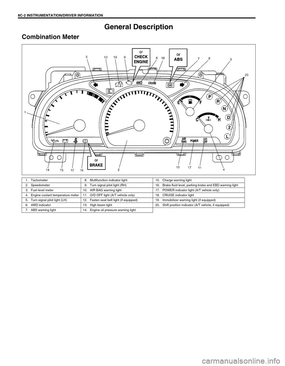
Combination Meter
1. Tachometer 8. Multifunction indicator light 15. Charge warning light
2. Speedometer 9. Turn signal pilot light (RH) 16. Brake fluid level, parking brake and EBD warning light
3. Fuel level meter 10. AIR BAG warning light 17. POWER indicator light (A/T vehicle only)
4. Engine coolant temperature meter 11. O/D OFF light (A/T vehicle only) 18. CRUISE indicator light
5. Turn signal pilot light (LH) 12. Fasten seat belt light (if equipped) 19. Immobilizer warning light (if equipped)
6. 4WD indicator 13. High beam light 20. Shift position indicator (A/T vehicle, if equipped)
7. ABS warning light 14. Engine oil pressure warning light