2001 SUZUKI GRAND VITARA Electrical system
[x] Cancel search: Electrical systemPage 410 of 656

AUTOMATIC TRANSMISSION (4 A/T) 7B1-1
7B1
SECTION 7B1
AUTOMATIC TRANSMISSION (4 A/T)
CONTENTS
General Description ......................................7B1-3
Electronic Shift Control System ................... 7B1-4
Automatic gear shift diagram................... 7B1-5
Diagnosis .......................................................7B1-7
On-Board Diagnostic System
(Vehicle without monitor connector) ............ 7B1-7
On-Board Diagnostic System
(Vehicle with monitor connector) ................. 7B1-8
Precaution in Diagnosing Trouble ............... 7B1-9
Automatic Transmission Diagnostic Flow
Table ......................................................... 7B1-10
Malfunction Indicator Lamp (MIL) Check... 7B1-13
“O/D OFF” Lamp Check ............................ 7B1-13
“POWER” Lamp Check ............................. 7B1-13
Diagnostic Trouble Code (DTC) Check ..... 7B1-13
Diagnostic Trouble Code Clearance ......... 7B1-13
Diagnostic Trouble Code Table ................. 7B1-14
Fail Safe Table .......................................... 7B1-14
Visual Inspection ....................................... 7B1-14
A/T Basic Check ........................................ 7B1-14
Trouble Diagnosis Table 1 ........................ 7B1-15
Trouble Diagnosis Table 2 ........................ 7B1-15
Trouble Diagnosis Table 3 ........................ 7B1-16
Scan Tool Data ......................................... 7B1-17
Inspection of PCM and Its Circuit .............. 7B1-17Wire Harness and Connectors .................. 7B1-17
Table A-1 : No TCC Lock-Up Occurs ........ 7B1-18
Table A-2 : No Gear Shift to O/D .............. 7B1-20
Table B-1 : “O/D OFF” Light Circuit Check
(“O/D OFF” Light Doesn’t Light at Ignition
Switch ON But Engine Starts Up) ............. 7B1-22
Table B-2 : “O/D OFF” Light Circuit Check
(“O/D OFF” Light Comes ON Steadily) ..... 7B1-23
Table B-3 : “POWER” Light Circuit Check
(“POWER” Light Doesn’t Light at Ignition
Switch ON But Engine Starts Up) ............. 7B1-24
Table B-4 : “POWER” Light Circuit Check
(“POWER” Light Comes ON Steadily) ...... 7B1-25
DTC P0705 (DTC NO.72) - Transmission
Range Sensor (Switch) Circuit Malfunction7B1-26
DTC P0715 (DTC NO.76) - Input/Turbine
Speed Sensor Circuit Malfunction............. 7B1-29
DTC P0720 (DTC NO.75) Output Speed
Sensor Circuit Malfunction ........................ 7B1-32
DTC P0743 (DTC NO.65/66) -
TCC (Lock-Up) Solenoid Electrical ........... 7B1-34
DTC P0753 (DTC NO.61/62)
Shift Solenoid-A (#1) Electrical
DTC P0758 (DTC NO.63/64)
Shift Solenoid-B (#2) Electrical ................. 7B1-36 WARNING:
For vehicles equipped with Supplemental Restraint (Air Bag) System:
Service on and around the air bag system components or wiring must be performed only by an
authorized SUZUKI dealer. Refer to “Air Bag System Components and Wiring Location View” under
“General Description” in air bag system section in order to confirm whether you are performing ser-
vice on or near the air bag system components or wiring. Please observe all WARNINGS and “Ser-
vice Precautions” under “On-Vehicle Service” in air bag system section before performing service
on or around the air bag system components or wiring. Failure to follow WARNINGS could result in
unintentional activation of the system or could render the system inoperative. Either of these two
conditions may result in severe injury.
Technical service work must be started at least 90 seconds after the ignition switch is turned to the
“LOCK” position and the negative cable is disconnected from the battery. Otherwise, the system
may be activated by reserve energy in the Sensing and Diagnostic Module (SDM).
NOTE:
For the descriptions (items) not found in this section, refer to the same section of the Service Manual
mentioned in FOREWORD of this manual.
Page 418 of 656

AUTOMATIC TRANSMISSION (4 A/T) 7B1-9
Precaution in Diagnosing Trouble
•Don’t disconnect couplers from PCM (ECM), battery cable
from battery, PCM ground wire harness from engine or main
fuse before checking the diagnosis information (DTC, freeze
frame data, etc.) stored in PCM memory. Such disconnec-
tion will clear memorized information in PCM memory.
•Using SUZUKI scan tool or also generic scan tool for vehicle
without monitor connector, the diagnostic information stored
in PCM memory can be checked and cleared as well. Before
its use, be sure to read Operator’s (Instruction) Manual sup-
plied with it carefully to have good understanding of its func-
tions and usage.
•Priorities for diagnosing troubles
If two or more diagnostic trouble codes (DTCs) are stored,
proceed to the flow table of the DTC which was detected
earliest in the order and follow the instruction in that table.
If no instructions are given, troubleshoot diagnostic trouble
codes according to the following priorities.
–Diagnostic trouble codes (DTCs) other than DTC P0171/
P0172/P0174/P0175 (Fuel system too lean/too rich), DTC
P0300/P0301/P0302/P0303/P0304/P0305/P0306 (Misfire
detected) and DTC P0400 (EGR flow malfunction)
–DTC P0171/P0172/P0174/P0175 (Fuel system too lean/too
rich) and DTC P0400 (EGR flow malfunction)
–DTC P0300/P0301/P0302/P0303/P0304/P0305/P0306
(Misfire detected)
•Be sure to read “PRECAUTIONS FOR ELECTRICAL CIR-
CUIT SERVICE” in Section 0A before inspection and
observe what is written there.
•PCM replacement
When substituting a known-good PCM, check for following
conditions.
Neglecting this check may result in damage to a good PCM.
–All relays and actuators have resistance of specified value.
–MAF sensor, MDP sensor, TP sensor and fuel tank pres-
sure sensor are in good condition. Also, the power circuit of
these sensors is not shorted to the ground.
Page 476 of 656

DIFFERENTIAL (FRONT) 7E-3
Diagnosis
Differential Assembly Diagnosis Table
4WD Control System Diagnostic Flow Table
Before performing the trouble diagnosis, check that the transfer and front differential are in good condition and
there is no air leakage from air hoses and the actuator. Refer to “4WD CONTROL SYSTEM INSPECTION” in
this section for air leakage.
Notes on system circuit inspection
•Be sure to read “PRECAUTIONS FOR ELECTRICAL CIRCUIT SERVICE” in Section 0A before circuit
inspection and observe what is written there.
•For system circuit, refer to the figure of “GENERAL DESCRIPTION” in this section.
•For terminal arrangement, refer to “4WD CONTROL CIRCUIT INSPECTION” in this section. Condition Possible Cause Correction
Gear noiseDeteriorated or water mixed lubricant Repair and replenish.
Inadequate or insufficient lubricant Repair and replenish.
Maladjusted backlash between bevel pinion and gear Adjust.
Improper tooth contact in the mesh between bevel pinion
and gearAdjust or replace.
Loose bevel gear securing bolts Replace or retighten.
Damaged side gear(s) or side pinion(s) Replace.
Bearing noise(Constant noise) Deteriorated or water mixed lubricant Repair and replenish.
(Constant noise) Inadequate or insufficientlubricant Repair and replenish.
(Noise while coasting) Damaged bearing(s) of bevel pinion Replace.
(Noise while turning) Damaged differential side bearing(s)
or axle bearing(s)Replace.
Oil leakageWorn or damaged oil seal Replace.
Excessive oil Adjust oil level.
Loose differential carrier bolts Replace or retighten.
2WD/4WD
switching errorDefective actuator Replace.
Abnormality in 4WD control system Inspect referring to “4WD
CONTROL SYSTEM DIAG-
NOSTIC FLOW TABLE”.
Page 510 of 656

BODY ELECTRICAL SYSTEM 8-1
6F1
6F2
6G
6H
6K
7A
8
6K
7C1
7D
7E
7F
8A
8D
8E
9
10
10A
10B
SECTION 8
BODY ELECTRICAL SYSTEM
Wiring System
(Harnesses, Connectors, Fuses, Relay, Switches, Grounds, System Circuit Diagram) .......... Section 8A
Lighting System .............................................................................................................................. Section 8B
Instrumententation and Driver Information .................................................................................. Section 8C
Windows, Mirrors, Security and Locks ......................................................................................... Section 8D
Immobilizer Control System............................................................................................................Section 8F
CONTENTS
General Description .......................................... 8-3
WARNING:
For vehicles equipped with Supplemental Restraint (Air Bag) System:
Service on and around the air bag system components or wiring must be performed only by an
authorized SUZUKI dealer. Refer to “Air Bag System Components and Wiring Location View” under
“General Description” in air bag system section in order to confirm whether you are performing ser-
vice on or near the air bag system components or wiring. Please observe all WARNINGS and “Ser-
vice Precautions” under “On-Vehicle Service” in air bag system section before performing service
on or around the air bag system components or wiring. Failure to follow WARNINGS could result in
unintentional activation of the system or could render the system inoperative. Either of these two
conditions may result in severe injury.
Technical service work must be started at least 90 seconds after the ignition switch is turned to the
“LOCK” position and the negative cable is disconnected from the battery. Otherwise, the system
may be activated by reserve energy in the Sensing and Diagnostic Module (SDM).
NOTE:
For the descriptions (items) not found in this section, refer to the same section of the Service Manual
mentioned in FOREWORD of this manual.
Page 511 of 656

8-2 BODY ELECTRICAL SYSTEM
General Description
WIRE COLOR SYMBOLS
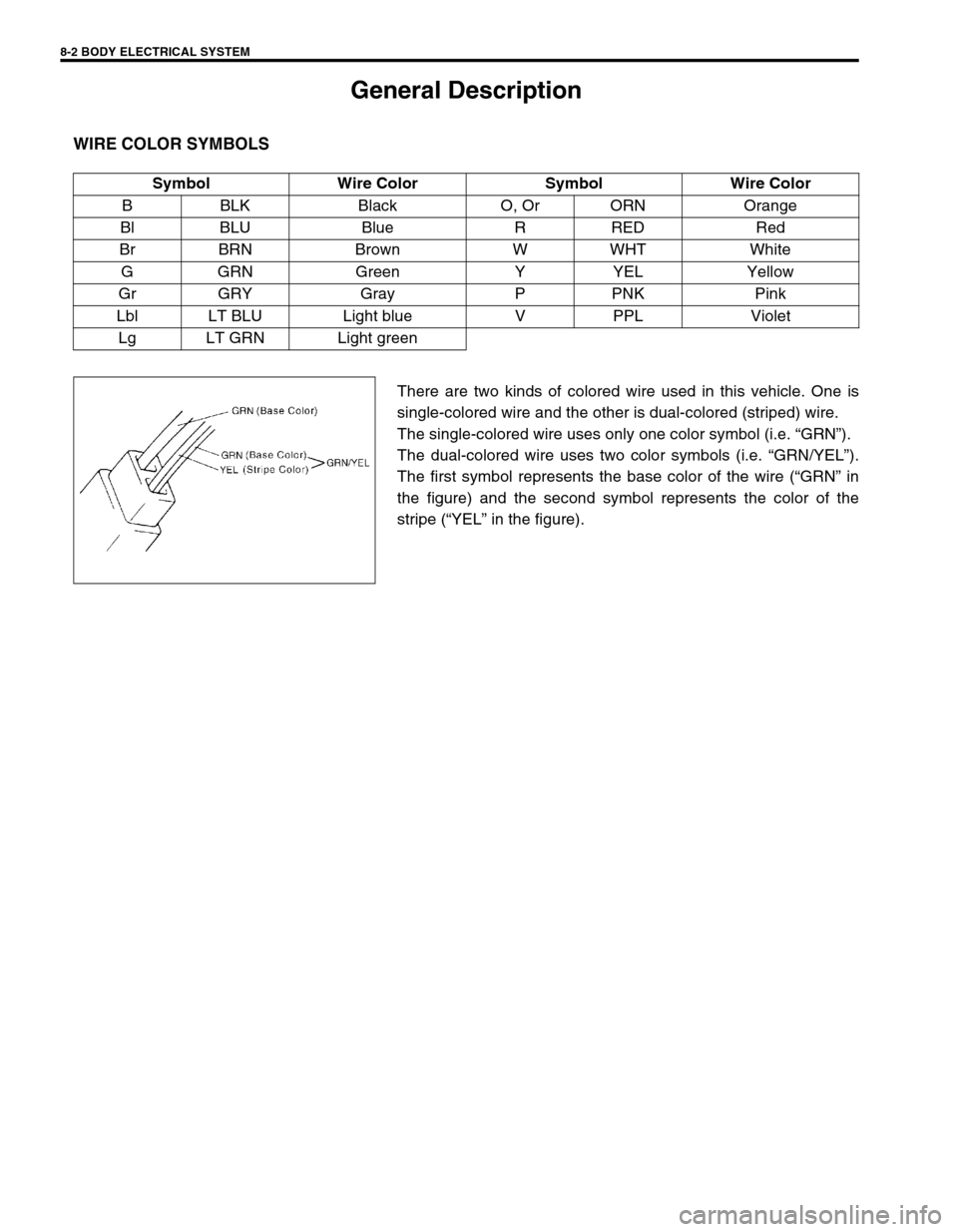
There are two kinds of colored wire used in this vehicle. One is
single-colored wire and the other is dual-colored (striped) wire.
The single-colored wire uses only one color symbol (i.e. “GRN”).
The dual-colored wire uses two color symbols (i.e. “GRN/YEL”).
The first symbol represents the base color of the wire (“GRN” in
the figure) and the second symbol represents the color of the
stripe (“YEL” in the figure). Symbol Wire Color Symbol Wire Color
B BLK Black O, Or ORN Orange
Bl BLU Blue R RED Red
Br BRN Brown W WHT White
GGRN Green Y YEL Yellow
Gr GRY Gray P PNK Pink
Lbl LT BLU Light blue V PPL Violet
Lg LT GRN Light green
Page 528 of 656

CRUISE CONTROL SYSTEM 8E-7
Note on System Circuit Inspection
Refer to “PRECAUTION FOR ELECTRICAL CIRCUIT SERVICE” in Section 0A. “RESUME/ACCEL”
switch fails to resume
preset vehicle speed
after cruise control is
cancelled.Main switch, “COAST/SET”, “RESUME/
ACCEL” and “CANCEL” switch circuits
faultyRefer to “CRUISE MAIN SWITCH,
COAT/SET, RESUME/ACCEL AND
CANCEL SWITCHES CIRCUITS
CHECK” in this section.
Actuator assembly faulty Replace actuator assembly.
Cruise control is not
cancelled even when
brake pedal is
depressed.Stop lamp switch circuit faulty Refer to “STOP LAMP SWITCH (WITH
PEDAL POSITION SWITCH) CIRCUITS
CHECK” in this section.
Actuator assembly faulty Replace actuator assembly.
Cruise control is not
cancelled even when
clutch pedal is
depressed.Clutch pedal position switch circuit faulty Refer to “CLUTCH PEDAL POSITION
SWITCH CIRCUIT CHECK” in this Sec-
tion.
Actuator assembly faulty Replace actuator assembly.
Cruise control is not
cancelled even when
selector lever is
shifted to “N” posi-
tion.Transmission range switch circuit (4 A/T
model only) faultyRefer to “TRANSMISSION RANGE
SWITCH CIRCUIT CHECK” in this sec-
tion.
Actuator assembly faulty Replace actuator assembly.
4 speed A/T gear shift-
ing is frequent
between 3rd and over-
drive when driving on
uphill road (Hunting).Throttle valve opening signal circuit faulty Refer to “THROTTLE VALVE OPENING
SIGNAL CIRCUIT CHECK” in this Sec-
tion.
Overdrive and TCC off command signal
circuit faultyRefer to “OVERDRIVE AND TCC OFF
COMMAND SIGNAL CIRCUIT CHECK”
in this section.
Actuator assembly faulty Replace actuator assembly.
4 speed A/T is not
shifted to overdrive
gear even though not
on uphill road.Throttle valve opening signal circuit faulty Refer to “THROTTLE VALVE OPENING
SIGNAL CIRCUIT CHECK” in this sec-
tion.
Overdrive and TCC off command signal
circuit faultyRefer to “OVERDRIVE AND TCC OFF
COMMAND SIGNAL CIRCUIT CHECK”
in this section.
Actuator assembly faulty Replace actuator assembly. Condition Possible Cause Correction
Page 583 of 656

10B-6 AIR BAG SYSTEM
Diagnosis
Diagnostic Trouble Code (DTC)
The AIR BAG DIAGNOSTIC SYSTEM CHECK must always be the starting point of any air bag system diagno-
sis. The AIR BAG DIAGNOSTIC SYSTEM CHECK checks for proper “AIR BAG” warning lamp operation and
checks for air bag diagnostic trouble codes (DTCs) using on-board diagnosis function or SUZUKI scan tool.
Use of Special Tool
You should be familiar with the tools listed in this section under the heading SPECIAL TOOLS. You should be
able to measure voltage and resistance. You should be familiar with proper use of a scan tool such as Air Bag
Driver/Passenger Load Tool, Connector Test Adapter Kit and the Digital Multimeter.
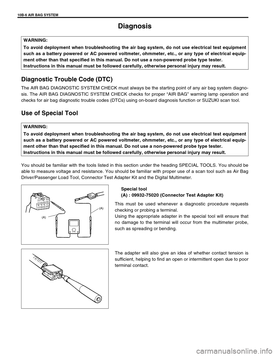
Special tool
(A) : 09932-75020 (Connector Test Adapter Kit)
This must be used whenever a diagnostic procedure requests
checking or probing a terminal.
Using the appropriate adapter in the special tool will ensure that
no damage to the terminal will occur from the multimeter probe,
such as spreading or bending.
The adapter will also give an idea of whether contact tension is
sufficient, helping to find an open or intermittent open due to poor
terminal contact. WARNING:
To avoid deployment when troubleshooting the air bag system, do not use electrical test equipment
such as a battery powered or AC powered voltmeter, ohmmeter, etc., or any type of electrical equip-
ment other than that specified in this manual. Do not use a non-powered probe type tester.
Instructions in this manual must be followed carefully, otherwise personal injury may result.
WARNING:
To avoid deployment when troubleshooting the air bag system, do not use electrical test equipment
such as a battery powered or AC powered voltmeter, ohmmeter, etc., or any type of electrical equip-
ment other than that specified in this manual. Do not use a non-powered probe type tester.
Instructions in this manual must be followed carefully, otherwise personal injury may result.
Page 584 of 656

AIR BAG SYSTEM 10B-7
Special tool
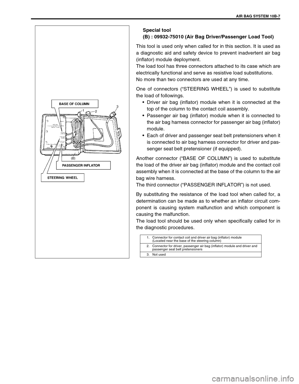
(B) : 09932-75010 (Air Bag Driver/Passenger Load Tool)
This tool is used only when called for in this section. It is used as
a diagnostic aid and safety device to prevent inadvertent air bag
(inflator) module deployment.
The load tool has three connectors attached to its case which are
electrically functional and serve as resistive load substitutions.
No more than two connectors are used at any time.
One of connectors (“STEERING WHEEL”) is used to substitute
the load of followings.
•Driver air bag (inflator) module when it is connected at the
top of the column to the contact coil assembly.
•Passenger air bag (inflator) module when it is connected to
the air bag harness connector for passenger air bag (inflator)
module.
•Each of driver and passenger seat belt pretensioners when it
is connected to air bag harness connector for driver and pas-
senger seat belt pretensioner (if equipped).
Another connector (“BASE OF COLUMN”) is used to substitute
the load of the driver air bag (inflator) module and the contact coil
assembly when it is connected at the base of the column to the air
bag wire harness.
The third connector (“PASSENGER INFLATOR”) is not used.
By substituting the resistance of the load tool when called for, a
determination can be made as to whether an inflator circuit com-
ponent is causing system malfunction and which component is
causing the malfunction.
The load tool should be used only when specifically called for in
the diagnostic procedures.
1. Connector for contact coil and driver air bag (inflator) module
(Located near the base of the steering column)
2. Connector for driver, passenger air bag (inflator) module and driver and
passenger seat belt pretensioners
3. Not used