2001 SUZUKI GRAND VITARA hose
[x] Cancel search: hosePage 571 of 656

10A-2 SEAT BELT
On-Vehicle Service
Service Precautions
Service and diagnosis
Before servicing or replacing seat belts, refer to following precautionary items.
•Seat belts should be normal relative to strap retractor and buckle portions.
•Keep sharp edges and damaging objects away from belts. Avoid bending or damaging any portion of belt
buckle, latch plate and ELR.
•Do not bleach or dye belt webbing. (Use only mild soap and lukewarm water to clean it.)
•When installing a seat belt anchor bolt, start bolt by hand to prevent cross-threading.
•Use only the correct seat belt anchor bolts and screws and tighten to the correct torque value.
•Do not attempt any repairs on retractor mechanisms or retractor covers. Replace defective assemblies with
new replacement parts.
•Keep belts dry and clean at all times.
•If there exist any parts in question, replace such parts.
•Replace belts whose webbing is cut or otherwise damaged.
•Do not put anything into trim panel opening which seat belt webbing passes through.
For Seat Belt with Pretensioner
Refer to “SERVICE AND DIAGNOSIS” of “SERVICE PRECAUTIONS” under “ON-VEHICLE SERVICE” in Sec-
tion 10B.
Disabling air bag system
Refer to “DISABLING AIR BAG SYSTEM” of “SERVICE PRECAUTIONS” under “ON-VEHICLE SERVICE” in
Section 10B.
Enabling air bag system
Refer to “ENABLING AIR BAG SYSTEM” of “SERVICE PRECAUTIONS” under “ON-VEHICLE SERVICE” in
Section 10B.
Handling and storage
Refer to “HANDLING AND STORAGE” of “SERVICE PRECAUTIONS” under “ON-VEHICLE SERVICE” in Sec-
tion 10B.
Disposal
Refer to “DISPOSAL” of “SERVICE PRECAUTIONS” under “ON-VEHICLE SERVICE” in Section 10B. WARNING:
If replacing seat belt is necessary, replace buckle and ELR (or webbing) together as a set. This is for
the reason of ensuring locking of tongue plate with buckle. If these parts are replaced individually,
such a locking condition may become unreliable. For this reason, SUZUKI will supply only the spare
buckle and ELR (or webbing) in a set part.
WARNING:
When performing service on or around air bag system components or air bag system wiring, disable
the air bag system. Refer to “DISABLING AIR BAG SYSTEM” of “SERVICE PRECAUTIONS” under
“ON-VEHICLE SERVICE” in Section 10B.
Failure to follow procedures could result in possible air bag activation, personal injury or unneeded
air bag system repairs.
Page 578 of 656
AIR BAG SYSTEM 10B-1
10B
SECTION 10B
AIR BAG SYSTEM
CONTENTS
General Description ......................................10B-3
System Components and Wiring Location
View and Connectors .................................. 10B-4
System Wiring Diagram............................... 10B-5
Diagnosis .......................................................10B-6
Diagnostic Trouble Code (DTC) .................. 10B-6
Use of Special Tool ..................................... 10B-6
Intermittents and Poor Connections ............ 10B-8
Air Bag Diagnostic System Check............... 10B-9
Air Bag Diagnostic System Check Flow
Table ......................................................... 10B-10
DTC Check ................................................ 10B-11
DTC Clearance ......................................... 10B-12
DTC Table ................................................. 10B-14
Table A - “AIR BAG” Warning Lamp
Comes ON Steady .................................... 10B-16
Table B - “AIR BAG” Warning Lamp Does
Not Come ON ............................................ 10B-16
Table C - “AIR BAG” Warning Lamp
Flashes ...................................................... 10B-16Table D - “AIR BAG” Warning Lamp
Cannot Indicate Flashing Pattern of DTC . 10B-16
Table E - SDM Cannot Communicate
through The Serial Data Circuit................. 10B-21
DTC B1015 - Passenger Air Bag Initiator
Circuit Resistance High............................. 10B-23
DTC B1016 - Passenger Air Bag Initiator
Circuit Resistance Low ............................. 10B-23
DTC B1018 - Passenger Air Bag Initiator
Circuit Short to Ground ............................. 10B-23
DTC B1019 - Passenger Air Bag Initiator
Circuit Short to Power Circuit .................... 10B-23
DTC B1021 – Driver Air Bag Initiator
Circuit Resistance High............................. 10B-28
DTC B1022 – Driver Air Bag Initiator
Circuit Resistance Low ............................. 10B-28
DTC B1024 – Driver Air Bag Initiator
Circuit Short to Ground ............................. 10B-28
DTC B1025 – Driver Air Bag Initiator
Circuit Short to Power Circuit .................... 10B-28 WARNING:
Service on or around the air bag system components or wiring must be performed only by an
authorized SUZUKI dealer. Please observe all WARNINGS and “Service Precautions” under “On-
Vehicle Service” in this section before performing service on or around the air bag system compo-
nents or wiring. Failure to follow WARNINGS could result in unintended activation of the system or
could render the system inoperative. Either of these two conditions may result in severe injury.
The procedures in this section must be followed in the order listed to disable the air bag system
temporarily and prevent false diagnostic trouble codes from setting. Failure to follow procedures
could result in possible activation of the air bag system, personal injury or otherwise unneeded air
bag system repairs.
CAUTION:
When fasteners are removed, always reinstall them at the same location from which they were
removed. If a fastener needs to be replaced, use the correct part number fastener for that application.
If the correct part number fastener is not available, a fastener of equal size and strength (or stronger)
may be used. Fasteners that are not reused, and those requiring thread-locking compound, will be
called out. The correct torque value must be used when installing fasteners that require it. If the above
conditions are not followed, parts or system damage could result.
NOTE:
For the descriptions (items) not found in this section, refer to the same section of the Service Manual
mentioned in the FOREWORD of this manual.
Page 580 of 656
AIR BAG SYSTEM 10B-3
General Description
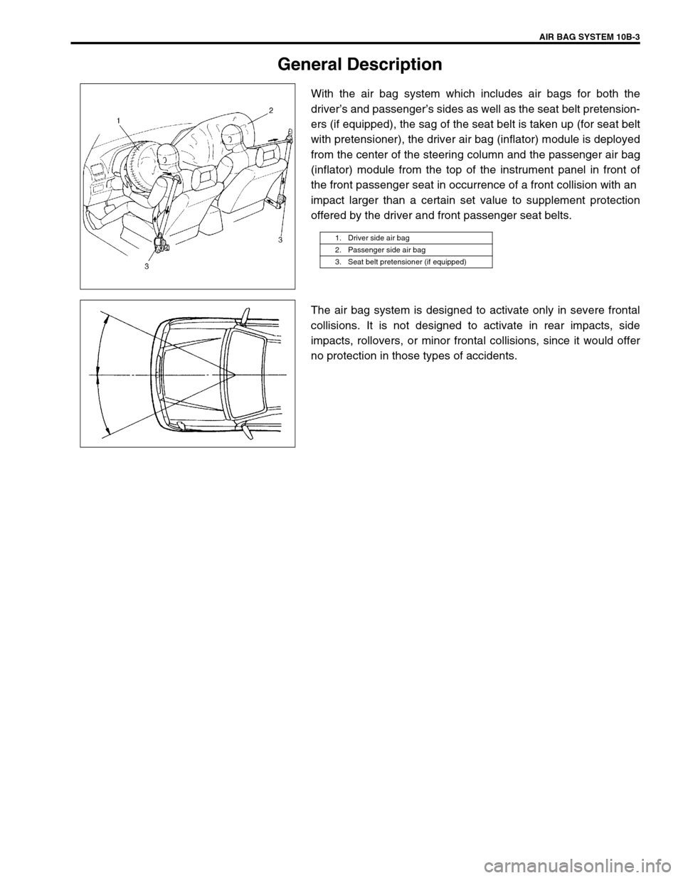
With the air bag system which includes air bags for both the
driver’s and passenger’s sides as well as the seat belt pretension-
ers (if equipped), the sag of the seat belt is taken up (for seat belt
with pretensioner), the driver air bag (inflator) module is deployed
from the center of the steering column and the passenger air bag
(inflator) module from the top of the instrument panel in front of
the front passenger seat in occurrence of a front collision with an
impact larger than a certain set value to supplement protection
offered by the driver and front passenger seat belts.
The air bag system is designed to activate only in severe frontal
collisions. It is not designed to activate in rear impacts, side
impacts, rollovers, or minor frontal collisions, since it would offer
no protection in those types of accidents.
1. Driver side air bag
2. Passenger side air bag
3. Seat belt pretensioner (if equipped)
Page 625 of 656

10B-48 AIR BAG SYSTEM
TABLE TEST DESCRIPTION
STEP 1 : This test rechecks “AIR BAG” warning lamp operation.
STEP 2 : This test rechecks whether an abnormality is in SDM.
DTC B1061 :
DTC B1071 – Internal SDM Fault
DTC WILL SET WHEN
An internal SDM fault is detected by SDM.
DTC B1013 – System Specifications Different from SDM Specifications
DTC WILL SET WHEN
Specifications of the air bag system differ from those of SDM.Step Action Yes No
1 1) This DTC is set when there is a trouble in
“AIR BAG” warning lamp circuit. Failure to
properly perform AIR BAG DIAGNOSTIC
SYSTEM CHECK may also result in mis-
diagnosis. Therefore, check “AIR BAG”
warning lamp circuit again according to
AIR BAG DIAGNOSTIC SYSTEM
CHECK.
Is “AIR BAG” warning lamp circuit in good
condition?Go to step 2. Repair “AIR BAG” warning
lamp circuit.
2 1) Clear DTC (Refer to DTC CLEARANCE).
2) Check DTC (Refer to DTC CHECK).
Is DTC B1061 set?Substitute a known-
good SDM and recheck.Recheck air bag system.
Refer to AIR BAG DIAG-
NOSTIC SYSTEM CHECK.
NOTE:
Upon completion of inspection and repair work, perform following items.
Reconnect all air bag system components, ensure all components are properly mounted.
Repeat AIR BAG DIAGNOSTIC SYSTEM CHECK to confirm that the trouble has been corrected.
NOTE:
DTC B1071 can never be cleared once it has been set.
1) Ignition switch OFF.
2) Replace SDM.
3) Repeat AIR BAG DIAGNOSTIC SYSTEM CHECK.
NOTE:
Before executing items below, be sure to perform AIR BAG DIAGNOSTIC SYSTEM CHECK.
1) Ignition switch OFF.
2) Replace SDM.
3) Repeat AIR BAG DIAGNOSTIC SYSTEM CHECK.
Page 633 of 656

10B-56 AIR BAG SYSTEM
Repairs and Inspections Required after an Accident
Accident with deployment/activation - component replacement
Certain air bag system components must be replaced. Those components are:
•Driver and passenger air bag (inflator) modules
–Replace with new one.
•Driver and Passenger seat belt pretensioners
–Replace with new one.
•SDM after detecting such collision as to meet deployment conditions
–Replace with new one.
•Forward sensors
–Replace with new one. CAUTION:
All air bag system components, including the electrical harness (component mounting points),
must be inspected after an accident. If any components are damaged or bent, they must be replaced
even if air bag system activation did not occur.
Never use air bag system parts from another vehicle.
Do not attempt to service the parts below. Service of these parts is by replacement only.
–Driver/Passenger air bag (inflator) modules, Driver/Passenger seat belt pretensioners
–Forward sensors
–SDM
–Contact coil and combination switch assembly
–Air bag wire harness
Proper operation of the sensors and air bag system requires that any repairs to the vehicle struc-
ture return it to its original production configuration.
CAUTION:
After detecting one time of such collision as to meet deployment conditions, the SDM must not be
used.
Refer to “AIR BAG DIAGNOSTIC SYSTEM CHECK” when checking the SDM.
Page 634 of 656

AIR BAG SYSTEM 10B-57
Accident with or without deployment/activation - component inspections
Certain air bag and restraint system components must be inspected after any crash, whether the air bag system
activated or not.
Those components are:
•Steering column and shaft joints
–Check for length, damage and bend according to “CHECK-
ING STEERING COLUMN FOR ACCIDENT DAMAGE” in
Section 3C1.
•Steering column bracket and capsules
–Check for damage and bent.
•If any faulty condition is found in above checks, replace faulty
part.
•Steering wheel and driver air bag (inflator) module
–Check for damage or air bag (inflator) module fitness.
–Check trim cover (pad surface) for cracks.
–Check wire harness and connector for damage or tightness.
•If any faulty condition is found in above checks, replace faulty
part.
•Contact coil and combination switch assembly
–Check wire harness and connectors for damage or tight-
ness.
–Check contact coil case for damage.
•If any faulty condition is found in above checks, replace.
Page 642 of 656

AIR BAG SYSTEM 10B-65
Air Bag (Inflator) Module and Seat Belt Pretensioner Disposal
Do not dispose of the live (undeployed) air bag (inflator) modules and seat belt pretensioners.
The method employed depends upon the final disposition of the particular vehicle, as noted in “DEPLOYMENT/
ACTIVATION OUTSIDE VEHICLE” and “DEPLOYMENT/ACTIVATION INSIDE VEHICLE”.
Deployment/Activation Outside Vehicle :
Follow this procedure when disposing of the air bag (inflator) module(s) and seat belt pretensioner(s) only (i.e.,
the vehicle itself will be used again).
Deployment/Activation Inside Vehicle :
Follow this procedure when scrapping the entire vehicle including the air bag (inflator) modules and seat belt
pretensioners.WARNING:
Failure to follow proper air bag (inflator) module and seat belt pretensioner disposal procedures can
result in air bag deployment and pretensioner activation which may cause personal injury.
Undeployed air bag (inflator) module/inactivated seat belt pretensioner must not be disposed of
through normal refuse channels.
The undeployed air bag (inflator) module and inactivated seat belt pretensioner contain substances
that can cause severe illness or personal injury if the sealed container is damaged during disposal.
WARNING:
Following precautions must be observed for this work. Failure to observe any of them may result in
personal injury.
The procedure should be followed strictly as described here.
Be sure to read “SERVICE PRECAUTIONS” beforehand.
To avoid an accidental deployment, this work should be performed by no more than one person.
Since the smoke is produced when air bag is deployed and pretensioner is activated, select a well-
ventilated area.
The air bag (inflator) module and seat belt pretensioner will immediately deploy/activate when a
power source is connected to it. Wear safety glasses throughout this entire deployment/activation
and disposal procedure.
Wear suitable ear protection when deploying air bag/activating pretensioner. Also, advise those
who are in the area close to deployment/activation site to wear suitable ear protection.
Do not deploy/activate two or more air bag system components (air bag (inflator) modules and seat
belt pretensioners) at the same time.
Never connect deployment harness to any power source before connecting deployment harness to
the air bag (inflator) module and seat belt pretensioner. Deployment harness shall remain shorted
and not be connected to a power source until the air bag is to be deployed and the pretensioner is
to be activated.