Page 1054 of 1306

neck to prevent the radiator filler neck from deforming.
+If any abnormalities are found, repair or replace the malfunc-
tioning parts.
Water Pump
REMOVAL AND INSTALLATION
CAUTION:
+When removing water pump assembly, be careful not to
get coolant on drive belt.
+Water pump cannot be disassembled and should be
replaced as a unit.
+After installing water pump, connect hose and clamp
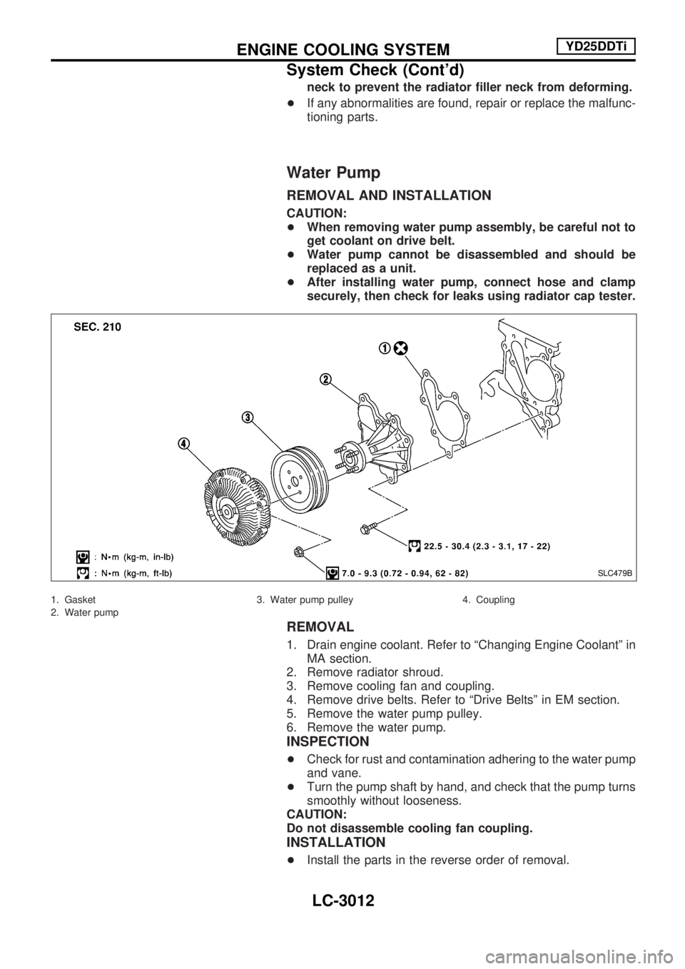
securely, then check for leaks using radiator cap tester.
1. Gasket
2. Water pump3. Water pump pulley 4. Coupling
REMOVAL
1. Drain engine coolant. Refer to ªChanging Engine Coolantº in
MA section.
2. Remove radiator shroud.
3. Remove cooling fan and coupling.
4. Remove drive belts. Refer to ªDrive Beltsº in EM section.
5. Remove the water pump pulley.
6. Remove the water pump.
INSPECTION
+Check for rust and contamination adhering to the water pump
and vane.
+Turn the pump shaft by hand, and check that the pump turns
smoothly without looseness.
CAUTION:
Do not disassemble cooling fan coupling.
INSTALLATION
+Install the parts in the reverse order of removal.
SLC479B
ENGINE COOLING SYSTEMYD25DDTi
System Check (Cont'd)
LC-3012
Page 1060 of 1306

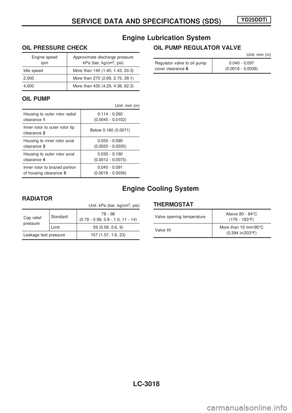
Engine Lubrication System
OIL PRESSURE CHECK
Engine speed
rpmApproximate discharge pressure
kPa (bar, kg/cm2, psi)
Idle speed More than 140 (1.40, 1.43, 20.3)
2,000 More than 270 (2.69, 2.75, 39.1)
4,000 More than 430 (4.29, 4.38, 62.3)
OIL PUMP
Unit: mm (in)
Housing to outer rotor radial
clearance10.114 - 0.260
(0.0045 - 0.0102)
Inner rotor to outer rotor tip
clearance2Below 0.180 (0.0071)
Housing to inner rotor axial
clearance30.050 - 0.090
(0.0020 - 0.0035)
Housing to outer rotor axial
clearance40.030 - 0.190
(0.0012 - 0.0075)
Inner rotor to brazed portion
of housing clearance50.045 - 0.091
(0.0018 - 0.0036)
OIL PUMP REGULATOR VALVE
Unit: mm (in)
Regulator valve to oil pump
cover clearance60.040 - 0.097
(0.0016 - 0.0038)
Engine Cooling System
RADIATOR
Unit: kPa (bar, kg/cm2, psi)
Cap relief
pressureStandard78-98
(0.78 - 0.98, 0.8 - 1.0, 11 - 14)
Limit 59 (0.59, 0.6, 9)
Leakage test pressure 157 (1.57, 1.6, 23)
THERMOSTAT
Valve opening temperatureAbove 80 - 84ÉC
(176 - 183ÉF)
Valve liftMore than 10 mm/95ÉC
(0.394 in/203ÉF)
SERVICE DATA AND SPECIFICATIONS (SDS)YD25DDTi
LC-3018
Page 1064 of 1306

Injection nozzle ........................... EC-3415, 3416
Injector removal and installation ........... EC-3034
Intake air temperature
sensor ................. EC-3160, 3193, 3503, 3504
Intake manifold ..................................... EM-3008
Interior lamp ........................................... EL-3054
K
KS - Wiring diagram ............................. EC-3261
Keyless entry system - See Multi-re-
mote control system .......................... EL-3136
Knock sensor (KS) ...................... EC-3260, 3261
L
License lampEL148Parking lamp .......... EL-3039
Liquid gasket application ...................... EM-3003
Location of electrical units ..................... EL-3163
Lubricants ............................................. MA-3008
Lubrication circuit (engine) .................... LC-3003
M
M/T removal and installation ................ MT-3002
MAFS - Wiring diagram .............. EC-3146, 3154
MAIN - Wiring diagram ..... EC-3124, 3470, 3471
METER - Wiring diagram ...................... EL-3062
MIL & Data link connectors circuit ........ EC-3396
MIL/DL - Wiring diagram .. EC-3396, 3646, 3647
MIRROR - Wiring diagram .................... EL-3116
MULTI - Wiring diagram ........................ EL-3137
Main gear (Transfer) .............................. TF-3004
Mainshaft (Transfer) .............................. TF-3004
Maintenance (engine) ................. MA-3010, 3011
Malfunction indicator lamp
(MIL) ........................................ EC-3429, 3430
Manifold tightening torque (intake &
exhaust) ............................................ MA-3011
Mass air flow sensor
(MAFS) .................... DT-3143, EC-3143, 3151
Meter ...................................................... EL-3056
Misfire .................................................... EC-3251
Model variation ....................................... GI-3004
Mud guard - See Exterior ...................... BT-3006
Multi-remote control system .................. EL-3136
Multiport fuel injection (MFI) system ..... EC-3024
N
NATS (Nissan Anti-theft System) .......... EL-3143
NATS - Wiring diagram ......................... EL-3146
Neutral position switch .......................... EC-3355
O
Oil change (capacity) ............................ MA-3008
Oil cooler (engine) ................................. LC-3006
Oil pan (engine) .................................... EM-3015
Oil pressure (engine) ............................. LC-3004
Oil pump (engine) .................................. LC-3004
Oil pump regulator valve (engine) ......... LC-3005
On board diagnostic
system ........................... EC-3049, 3428, 3429
P
P/ANT - Wiring diagram ........................ EL-3115
PCV (positive crankcase
ventilation) ..................... EC-3032, 3414, 3415
PCV filter replacement ......................... MA-3010
PGC/V - Wiring diagram ....................... EC-3286
PNP/SW - Wiring diagram .................... EC-3358
POWER - Wiring diagram ..................... EL-3006
PST/SW - Wiring diagram .................... EC-3386
Park/Neutral position
switch ............................ EC-3355, 3633, 3634
Parking lamp .......................................... EL-3039
Piston assembly ................................... EM-3081
Piston pin inspection ............................ EM-3071
Piston ring inspection ........................... EM-3071
Piston to bore clearance ...................... EM-3073
Power door mirror .................................. EL-3116
Power steering oil pressure switch ....... EC-3385
Power supply routing ............................. EL-3005
Power transistor & ignition coil ............. EC-3361
Power window ....................................... EL-3120
Priming pump .............................. EC-3444, 3445
Q
Quick-glow system ...................... EC-3621, 3622
R
R/FOG - Wiring diagram ....................... EL-3045
ROOM/L - Wiring diagram ..................... EL-3054
Radiator fan - See Cooling fan ............. LC-3016
Radiator ................................................. LC-3015
Rear case (Transfer) ............................. TF-3003
Rear fog lamp ........................................ EL-3045
Rear window defogger .......................... EL-3112
Refrigerant connection precaution ........ HA-3002
Refrigerant lines .................................... HA-3030
Road wheel size ..................................... GI-3007
Room lamp ............................................ EL-3054
ALPHABETICAL INDEX
IDX-3004
Page:
< prev 1-8 9-16 17-24