2001 NISSAN PATHFINDER fuse
[x] Cancel search: fusePage 55 of 289

Driver's supplemental air bag (P.1-10)Cruise control
switch (P.5-17)
Outside mirror remote control
(P.3-15) Headlight/dimmer/turn signal switch (P.2-19)
Front fog light switch (P.2-23)
Steering switch for audio control
(P.4-25)Meters/gauges (P.2-3)Windshield
and rear
window wiper/
washer
switch
(P.2-18)
Hazard warning
flasher switch
(P.2-23)Center ventilator (P.4-2)
Heater/air conditioner control (P.4-2)Compass/outside air temperature display (P.2-6)
Passenger supplemental air bag (P.1-10)
Side ventilator (P.4-2)
Glove box (P.2-29)
Power outlet (P.2-25) or Cigarette lighter (P.2-26)
Radio (P.4-11)/CD player (P.4-13) or Navigation system* Glass hatch/
outside mirror
defogger switch
(P.2-19) Ignition switch/steering
lock (P.5-6)
Heated seat switch (P.2-24)
or 4WD shift switch (P.5-24) Tilting steering wheel
adjust lever (P.3-14) Fuse box cover (P.8-25)/
Tray (P.2-27)Clock (P.2-25)
Instrument brightness control
(P.2-21)
SIC1438
See the page indicated in parentheses for operating details.
*: Refer to the separate Navigation System Owner's Manual.
Security indicator
light (P.2-15)
Hood release handle (P.3-9)Heated seat switch (P.2-24) (4WD shift switch equipped models)
INSTRUMENT PANEL2-2
Instruments and controls
Z
00.1.10/R50-D/V5
X
Page 79 of 289

The power outlet is for powering electrical
accessories such as cellular telephones.
CAUTION
IUse caution as the outlet and plug
may be hot during or immediately
after use.
IThis power outlet is not designed for
use with a cigarette lighter unit.
IDo not use with accessories that ex-
ceed a 12 volt, 120W (10A) power
draw. Do not use double adapters or
more than one electrical accessory.
IUse only one power outlet at a time.
IUse this power outlet with the engine
running. (If the engine is stopped,
this could result in a discharged bat-
tery.)
IAvoid using when the air conditioner,
headlights or rear window defogger
is on.
IBefore inserting or disconnecting a
plug, be sure to turn off the powerswitch of electrical accessory being
used or the ACC power of the vehicle.
IPush the plug in as far as it will go. If
good contact is not made, the plug
may overheat or the internal tempera-
ture fuse may blow.
IWhen not in use, be sure to close the
cap. Do not allow water to contact the
socket.
SIC0685B
CIGARETTE LIGHTER AND
ASHTRAY (if so equipped)
2-26
Instruments and controls
Z
00.1.10/R50-D/V5
X
Page 116 of 289

any positions other than ON.
4. Push the SET switch and, within 5 seconds,
push the memory switch 1 or 2 fully for at
least 1 second.
The indicator light for the pushed memory
switch will come on and stay on for approxi-
mately 5 seconds after pushing the switch.
After the indicator light goes off, the se-
lected positions are stored in the selected
memory (1 or 2).
If memory is stored in the same memory
switch, the previous memory will be de-
leted.
Confirming memory storageITurn the ignition ON and push the SET
switch. If the main memory has not been
stored, the indicator light will come on for
approximately 0.5 seconds. When the
memory has stored the position, the indica-
tor light will stay on for approximately 5
seconds.
IIf the battery cable is disconnected, or if the
fuse blows, the memory will be canceled. In
such a case, reset the desired positions
using the following procedures.
1. Open and close the driver's door more thantwo times with the ignition key in the LOCK
position.
2. Reset the desired position using the previ-
ous procedure.
Selecting the memorized position1. Set the automatic transmission selector le-
ver to the P (Park) position.
2. Turn the ignition ON.
3. Push the memory switch 1 or 2 fully for at
least 1 second.
The driver's seat will move to the memo-
rized position with the indicator light flash-
ing, and then the light will stay on for
approximately 5 seconds.
When the memory switch 1 or 2 is pushed with
the driver's door open and then the key in-
serted into the ignition switch within approxi-
mately 1 minute, the driver's seat will move to
the memorized position.System operationThe automatic drive positioner system will not
work or will stop operating under the following
conditions:
Iwhen the vehicle speed is above 4 MPH (7
km/h).Iwhen any two or more of the memory
switches are simultaneously pressed while
the automatic drive positioner is operating.
Iwhen the adjusting switch for the driver's
seat is turned on while the automatic drive
positioner is operating.
Iwhen the cancel switch located on the
instrument panel is pushed to cancel.
Iwhen the memory switch 1 or 2 is not
pushed for at least 1 second.
Iwhen the seat has been already moved to
the memorized position.
Iwhen no seat position is stored in the
memory switch.
Pre-driving checks and adjustments
3-17
Z
00.1.10/R50-D/V5
X
Page 133 of 289

cies and stops at the next broadcasting sta-
tion.
Push the SEEK/SCAN tuning button
or
for more than 1.5 seconds. SCAN tuning
begins from high to low or low to high frequen-
cies and stops at each broadcasting station for
10 seconds. Pushing the button again during
this 10 seconds period will stop SCAN tuning
and the radio will remain tuned to that station.
If the SEEK/SCAN tuning button is not pushed
within 10 seconds, SCAN tuning moves to the
next station.Station memory operations:
Twelve stations can be set for the FM band
(six for FM1, six for FM2).
Six stations can be set for the AM band.
1. Tune to the desired station using the
SEEK/SCAN or TUNE button.
2. Select the desired station and keep pushing
any of the desired station memory buttons
(1 to 6) until a beep sound is heard. (For
example, in the diagram ch2 is to be memo-
rized. The radio mutes when the select
button is pushed.)
3. The indicator ch2 will then come on and the
sound will resume. Memorizing is now com-
plete.
4. Other buttons can be set in the same
manner.
If the battery cable is disconnected, or if the
fuse blows, the radio memory will be can-
celled. In that case, reset the desired stations.
Cassette tape player operationTurn the ignition key to ACC or ON, and then
lightly insert the cassette tape into the tape
door. The cassette tape will be automatically
pulled into the player.
The radio or CD will turn off (if it is on) and the
SAA0475
4-16
Heater, air conditioner and audio systems
Z
00.1.10/R50-D/V5
X
Page 139 of 289

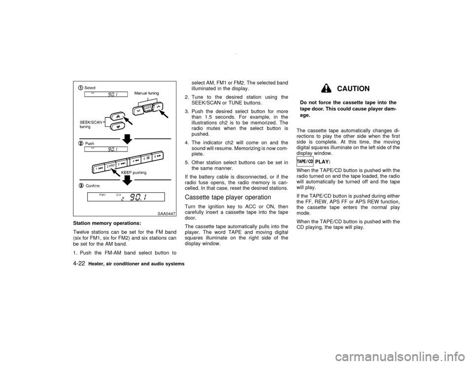
Station memory operations:
Twelve stations can be set for the FM band
(six for FM1, six for FM2) and six stations can
be set for the AM band.
1. Push the FM-AM band select button toselect AM, FM1 or FM2. The selected band
illuminated in the display.
2. Tune to the desired station using the
SEEK/SCAN or TUNE buttons.
3. Push the desired select button for more
than 1.5 seconds. For example, in the
illustrations ch2 is to be memorized. The
radio mutes when the select button is
pushed.
4. The indicator ch2 will come on and the
sound will resume. Memorizing is now com-
plete.
5. Other station select buttons can be set in
the same manner.
If the battery cable is disconnected, or if the
radio fuse opens, the radio memory is can-
celled. In that case, reset the desired stations.
Cassette tape player operationTurn the ignition key to ACC or ON, then
carefully insert a cassette tape into the tape
door.
The cassette tape automatically pulls into the
player. The word TAPE and moving digital
squares illuminate on the right side of the
display window.
CAUTION
Do not force the cassette tape into the
tape door. This could cause player dam-
age.
The cassette tape automatically changes di-
rections to play the other side when the first
side is complete. At this time, the moving
digital squares illuminate on the left side of the
display window.
PLAY:
When the TAPE/CD button is pushed with the
radio turned on and the tape loaded, the radio
will automatically be turned off and the tape
will play.
If the TAPE/CD button is pushed during either
the FF, REW, APS FF or APS REW function,
the cassette tape enters the normal play
mode.
When the TAPE/CD button is pushed with the
CD playing, the tape will play.
SAA0447
4-22
Heater, air conditioner and audio systems
Z
00.1.10/R50-D/V5
X
Page 206 of 289

8 Do-it-yourselfMaintenance precautions .......................................... 8-2
Engine compartment check locations ....................... 8-4
Engine cooling system .............................................. 8-6
Checking engine coolant level ............................. 8-6
Changing engine coolant ..................................... 8-7
Engine oil ................................................................ 8-10
Checking engine oil level ................................... 8-10
Changing engine oil ........................................... 8-11
Changing engine oil filter ................................... 8-12
Automatic transmission fluid ................................... 8-13
Temperature conditions for checking ................. 8-14
Power steering fluid ................................................ 8-15
Brake and clutch fluid ............................................. 8-15
Brake fluid .......................................................... 8-15
Clutch fluid.......................................................... 8-16
Window washer fluid ............................................... 8-17
Window washer fluid reservoir ........................... 8-17
Battery ..................................................................... 8-18
Jump starting ...................................................... 8-18
Drive belts ............................................................... 8-19
Spark plugs ............................................................. 8-19
Replacing spark plugs ........................................ 8-19Air cleaner ............................................................... 8-20
Windshield wiper blades ......................................... 8-21
Cleaning ............................................................. 8-21
Replacing............................................................ 8-21
Parking brake and brake pedal ............................... 8-22
Checking parking brake ..................................... 8-22
Checking brake pedal ........................................ 8-22
Brake booster ..................................................... 8-23
Clutch pedal ............................................................ 8-24
Checking clutch pedal ........................................ 8-24
Fuses....................................................................... 8-24
Engine compartment .......................................... 8-24
Passenger compartment .................................... 8-25
Multi-remote controller battery replacement....... 8-25
Lights ....................................................................... 8-27
Headlights........................................................... 8-28
Wheels and tires ..................................................... 8-31
Tire pressure ...................................................... 8-31
Types of tires...................................................... 8-32
Tire chains .......................................................... 8-33
Changing wheels and tires ................................. 8-33
Clutch housing drain............................... 8-37Z
00.1.10/R50-D/V5
X
Page 229 of 289

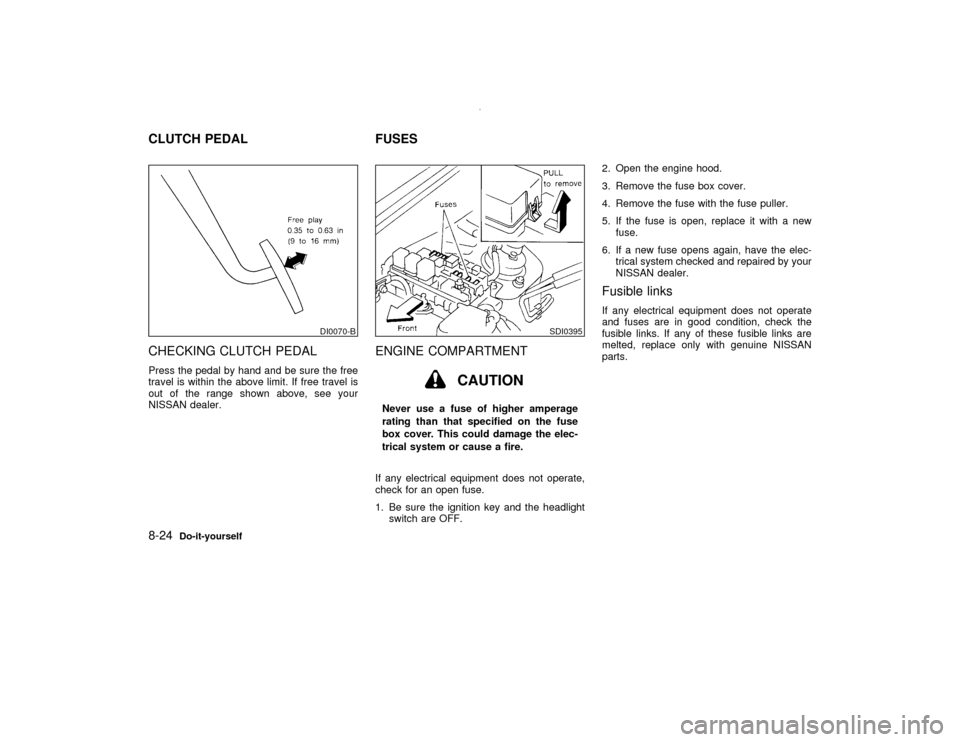
CHECKING CLUTCH PEDALPress the pedal by hand and be sure the free
travel is within the above limit. If free travel is
out of the range shown above, see your
NISSAN dealer.
ENGINE COMPARTMENT
CAUTION
Never use a fuse of higher amperage
rating than that specified on the fuse
box cover. This could damage the elec-
trical system or cause a fire.
If any electrical equipment does not operate,
check for an open fuse.
1. Be sure the ignition key and the headlight
switch are OFF.2. Open the engine hood.
3. Remove the fuse box cover.
4. Remove the fuse with the fuse puller.
5. If the fuse is open, replace it with a new
fuse.
6. If a new fuse opens again, have the elec-
trical system checked and repaired by your
NISSAN dealer.
Fusible linksIf any electrical equipment does not operate
and fuses are in good condition, check the
fusible links. If any of these fusible links are
melted, replace only with genuine NISSAN
parts.
DI0070-B
SDI0395
CLUTCH PEDAL FUSES8-24
Do-it-yourself
Z
00.1.10/R50-D/V5
X
Page 230 of 289

PASSENGER COMPARTMENTIf any electrical equipment does not operate,
check for an open fuse.
1. Be sure the ignition key and the headlight
switch are OFF.
2. Pull to open the fuse box cover/coin tray.
3. Pull down the fuse box cover/coin tray to
remove it.
4. Remove the fuse with the fuse puller.
5. If the fuse is open, replace it with a new
fuse.6. If a new fuse opens again, have the elec-
trical system checked and repaired by your
NISSAN dealer.
MULTI-REMOTE CONTROLLER
BATTERY REPLACEMENTReplace the battery as follows:
1. Open the lid using a suitable tool.
SDI1169
SPA1046
Do-it-yourself
8-25
Z
00.1.10/R50-D/V5
X