2001 NISSAN ALMERA TINO fuel pump
[x] Cancel search: fuel pumpPage 1489 of 3051
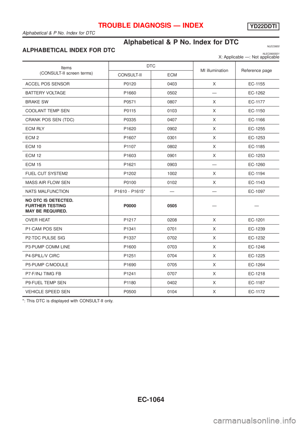
Alphabetical & P No. Index for DTCNLEC0600ALPHABETICAL INDEX FOR DTCNLEC0600S01X: Applicable Ð: Not applicable
Items
(CONSULT-II screen terms)DTC
MI illumination Reference page
CONSULT-II ECM
ACCEL POS SENSOR P0120 0403 X EC-1155
BATTERY VOLTAGE P1660 0502 Ð EC-1262
BRAKE SW P0571 0807 X EC-1177
COOLANT TEMP SEN P0115 0103 X EC-1150
CRANK POS SEN (TDC) P0335 0407 X EC-1166
ECM RLY P1620 0902 X EC-1255
ECM 2 P1607 0301 X EC-1253
ECM 10 P1107 0802 X EC-1185
ECM 12 P1603 0901 X EC-1253
ECM 15 P1621 0903 Ð EC-1260
FUEL CUT SYSTEM2 P1202 1002 X EC-1194
MASS AIR FLOW SEN P0100 0102 X EC-1143
NATS MALFUNCTION P1610 - P1615* Ð Ð EC-1097
NO DTC IS DETECTED.
FURTHER TESTING
MAY BE REQUIRED.P0000 0505ÐÐ
OVER HEAT P1217 0208 X EC-1201
P1´CAM POS SEN P1341 0701 X EC-1239
P2´TDC PULSE SIG P1337 0702 X EC-1232
P3´PUMP COMM LINE P1600 0703 X EC-1246
P4´SPILL/V CIRC P1251 0704 X EC-1225
P5´PUMP C/MODULE P1690 0705 X EC-1264
P7´F/INJ TIMG FB P1241 0707 X EC-1218
P9´FUEL TEMP SEN P1180 0402 X EC-1187
VEHICLE SPEED SEN P0500 0104 X EC-1172
*: This DTC is displayed with CONSULT-II only.
TROUBLE DIAGNOSIS Ð INDEXYD22DDTI
Alphabetical & P No. Index for DTC
EC-1064
Page 1490 of 3051
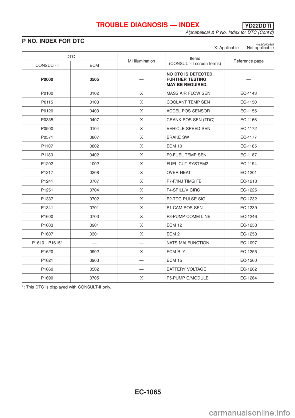
P NO. INDEX FOR DTC=NLEC0600S02X: Applicable Ð: Not applicable
DTC
MI illuminationItems
(CONSULT-II screen terms)Reference page
CONSULT-II ECM
P0000 0505ÐNO DTC IS DETECTED.
FURTHER TESTING
MAY BE REQUIRED.Ð
P0100 0102 X MASS AIR FLOW SEN EC-1143
P0115 0103 X COOLANT TEMP SEN EC-1150
P0120 0403 X ACCEL POS SENSOR EC-1155
P0335 0407 X CRANK POS SEN (TDC) EC-1166
P0500 0104 X VEHICLE SPEED SEN EC-1172
P0571 0807 X BRAKE SW EC-1177
P1107 0802 X ECM 10 EC-1185
P1180 0402 X P9´FUEL TEMP SEN EC-1187
P1202 1002 X FUEL CUT SYSTEM2 EC-1194
P1217 0208 X OVER HEAT EC-1201
P1241 0707 X P7´F/INJ TIMG FB EC-1218
P1251 0704 X P4´SPILL/V CIRC EC-1225
P1337 0702 X P2´TDC PULSE SIG EC-1232
P1341 0701 X P1´CAM POS SEN EC-1239
P1600 0703 X P3´PUMP COMM LINE EC-1246
P1603 0901 X ECM 12 EC-1253
P1607 0301 X ECM 2 EC-1253
P1610 - P1615* Ð Ð NATS MALFUNCTION EC-1097
P1620 0902 X ECM RLY EC-1255
P1621 0903 Ð ECM 15 EC-1260
P1660 0502 Ð BATTERY VOLTAGE EC-1262
P1690 0705 X P5´PUMP C/MODULE EC-1264
*: This DTC is displayed with CONSULT-II only.
TROUBLE DIAGNOSIS Ð INDEXYD22DDTI
Alphabetical & P No. Index for DTC (Cont'd)
EC-1065
Page 1493 of 3051
SAT652J
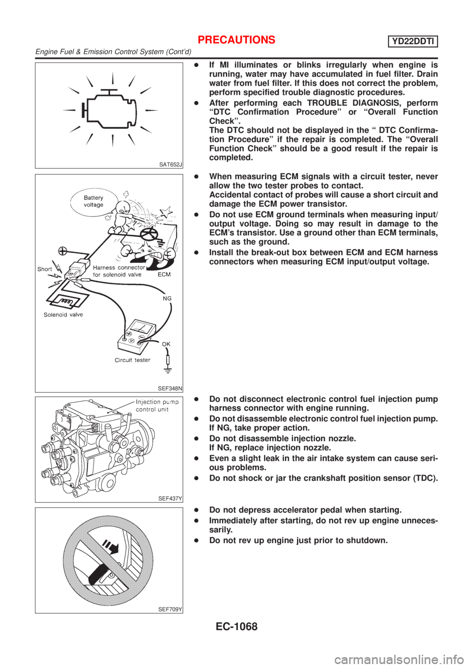
+If MI illuminates or blinks irregularly when engine is
running, water may have accumulated in fuel filter. Drain
water from fuel filter. If this does not correct the problem,
perform specified trouble diagnostic procedures.
+After performing each TROUBLE DIAGNOSIS, perform
ªDTC Confirmation Procedureº or ªOverall Function
Checkº.
The DTC should not be displayed in the ª DTC Confirma-
tion Procedureº if the repair is completed. The ªOverall
Function Checkº should be a good result if the repair is
completed.
SEF348N
+When measuring ECM signals with a circuit tester, never
allow the two tester probes to contact.
Accidental contact of probes will cause a short circuit and
damage the ECM power transistor.
+Do not use ECM ground terminals when measuring input/
output voltage. Doing so may result in damage to the
ECM's transistor. Use a ground other than ECM terminals,
such as the ground.
+Install the break-out box between ECM and ECM harness
connectors when measuring ECM input/output voltage.
SEF437Y
+Do not disconnect electronic control fuel injection pump
harness connector with engine running.
+Do not disassemble electronic control fuel injection pump.
If NG, take proper action.
+Do not disassemble injection nozzle.
If NG, replace injection nozzle.
+Even a slight leak in the air intake system can cause seri-
ous problems.
+Do not shock or jar the crankshaft position sensor (TDC).
SEF709Y
+Do not depress accelerator pedal when starting.
+Immediately after starting, do not rev up engine unneces-
sarily.
+Do not rev up engine just prior to shutdown.
PRECAUTIONSYD22DDTI
Engine Fuel & Emission Control System (Cont'd)
EC-1068
Page 1495 of 3051
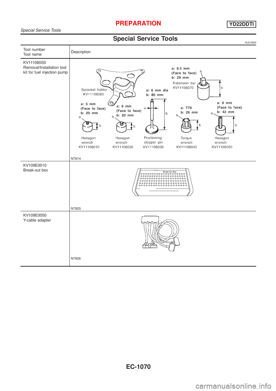
Special Service ToolsNLEC0605
Tool number
Tool nameDescription
KV111060S0
Removal/Installation tool
kit for fuel injection pump
NT814
KV109E0010
Break-out box
NT825
KV109E0050
Y-cable adapter
NT826
PREPARATIONYD22DDTI
Special Service Tools
EC-1070
Page 1503 of 3051
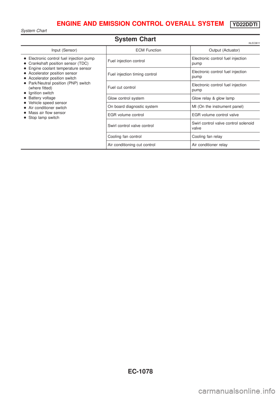
System ChartNLEC0611
Input (Sensor) ECM Function Output (Actuator)
+Electronic control fuel injection pump
+Crankshaft position sensor (TDC)
+Engine coolant temperature sensor
+Accelerator position sensor
+Accelerator position switch
+Park/Neutral position (PNP) switch
(where fitted)
+Ignition switch
+Battery voltage
+Vehicle speed sensor
+Air conditioner switch
+Mass air flow sensor
+Stop lamp switchFuel injection controlElectronic control fuel injection
pump
Fuel injection timing controlElectronic control fuel injection
pump
Fuel cut controlElectronic control fuel injection
pump
Glow control system Glow relay & glow lamp
On board diagnostic system MI (On the instrument panel)
EGR volume control EGR volume control valve
Swirl control valve controlSwirl control valve control solenoid
valve
Cooling fan control Cooling fan relay
Air conditioning cut control Air conditioner relay
ENGINE AND EMISSION CONTROL OVERALL SYSTEMYD22DDTI
System Chart
EC-1078
Page 1504 of 3051
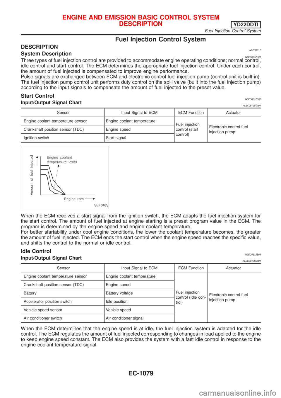
Fuel Injection Control System
DESCRIPTIONNLEC0612System DescriptionNLEC0612S01Three types of fuel injection control are provided to accommodate engine operating conditions; normal control,
idle control and start control. The ECM determines the appropriate fuel injection control. Under each control,
the amount of fuel injected is compensated to improve engine performance.
Pulse signals are exchanged between ECM and electronic control fuel injection pump (control unit is built-in).
The fuel injection pump control unit performs duty control on the spill valve (built into the fuel injection pump)
according to the input signals to compensate the amount of fuel injected to the preset value.
Start ControlNLEC0612S02Input/Output Signal ChartNLEC0612S0201
Sensor Input Signal to ECM ECM Function Actuator
Engine coolant temperature sensor Engine coolant temperature
Fuel injection
control (start
control)Electronic control fuel
injection pump Crankshaft position sensor (TDC) Engine speed
Ignition switch Start signal
SEF648S
When the ECM receives a start signal from the ignition switch, the ECM adapts the fuel injection system for
the start control. The amount of fuel injected at engine starting is a preset program value in the ECM. The
program is determined by the engine speed and engine coolant temperature.
For better startability under cool engine conditions, the lower the coolant temperature becomes, the greater
the amount of fuel injected. The ECM ends the start control when the engine speed reaches the specific value,
and shifts the control to the normal or idle control.
Idle ControlNLEC0612S03Input/Output Signal ChartNLEC0612S0301
Sensor Input Signal to ECM ECM Function Actuator
Engine coolant temperature sensor Engine coolant temperature
Fuel injection
control (Idle con-
trol)Electronic control fuel
injection pump Crankshaft position sensor (TDC) Engine speed
Battery Battery voltage
Accelerator position switch Idle position
Vehicle speed sensor Vehicle speed
Air conditioner switch Air conditioner signal
When the ECM determines that the engine speed is at idle, the fuel injection system is adapted for the idle
control. The ECM regulates the amount of fuel injected corresponding to changes in load applied to the engine
to keep engine speed constant. The ECM also provides the system with a fast idle control in response to the
engine coolant temperature signal.
ENGINE AND EMISSION BASIC CONTROL SYSTEM
DESCRIPTION
YD22DDTI
Fuel Injection Control System
EC-1079
Page 1505 of 3051
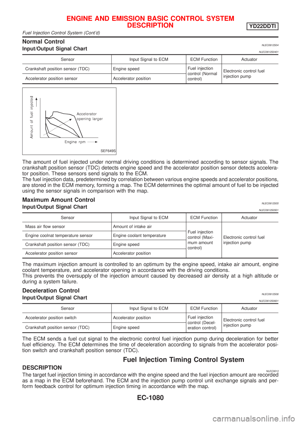
Normal ControlNLEC0612S04Input/Output Signal ChartNLEC0612S0401
Sensor Input Signal to ECM ECM Function Actuator
Crankshaft position sensor (TDC) Engine speedFuel injection
control (Normal
control)Electronic control fuel
injection pump
Accelerator position sensor Accelerator position
SEF649S
The amount of fuel injected under normal driving conditions is determined according to sensor signals. The
crankshaft position sensor (TDC) detects engine speed and the accelerator position sensor detects accelera-
tor position. These sensors send signals to the ECM.
The fuel injection data, predetermined by correlation between various engine speeds and accelerator positions,
are stored in the ECM memory, forming a map. The ECM determines the optimal amount of fuel to be injected
using the sensor signals in comparison with the map.
Maximum Amount ControlNLEC0612S05Input/Output Signal ChartNLEC0612S0501
Sensor Input Signal to ECM ECM Function Actuator
Mass air flow sensor Amount of intake air
Fuel injection
control (Maxi-
mum amount
control)Electronic control fuel
injection pump Engine coolnat temperature sensor Engine coolant temperature
Crankshaft position sensor (TDC) Engine speed
Accelerator position sensor Accelerator position
The maximum injection amount is controlled to an optimum by the engine speed, intake air amount, engine
coolant temperature, and accelerator opening in accordance with the driving conditions.
This prevents the oversupply of the injection amount caused by decreased air density at a high altitude or
during a system failure.
Deceleration ControlNLEC0612S06Input/Output Signal ChartNLEC0612S0601
Sensor Input Signal to ECM ECM Function Actuator
Accelerator position switch Accelerator positionFuel injection
control (Decel-
eration control)Electronic control fuel
injection pump
Crankshaft position sensor (TDC) Engine speed
The ECM sends a fuel cut signal to the electronic control fuel injection pump during deceleration for better
fuel efficiency. The ECM determines the time of deceleration according to signals from the accelerator posi-
tion switch and crankshaft position sensor (TDC).
Fuel Injection Timing Control System
DESCRIPTIONNLEC0613The target fuel injection timing in accordance with the engine speed and the fuel injection amount are recorded
as a map in the ECM beforehand. The ECM and the injection pump control unit exchange signals and per-
form feedback control for optimum injection timing in accordance with the map.
ENGINE AND EMISSION BASIC CONTROL SYSTEM
DESCRIPTION
YD22DDTI
Fuel Injection Control System (Cont'd)
EC-1080
Page 1506 of 3051
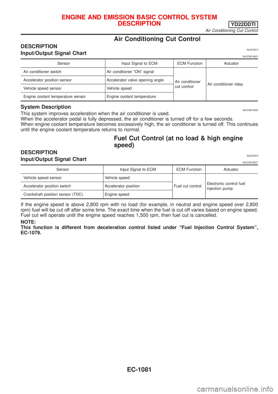
Air Conditioning Cut Control
DESCRIPTIONNLEC0614Input/Output Signal ChartNLEC0614S01
Sensor Input Signal to ECM ECM Function Actuator
Air conditioner switch Air conditioner ªONº signal
Air conditioner
cut controlAir conditioner relay Accelerator position sensor Accelerator valve opening angle
Vehicle speed sensor Vehicle speed
Engine coolant temperature sensor Engine coolant temperature
System DescriptionNLEC0614S02This system improves acceleration when the air conditioner is used.
When the accelerator pedal is fully depressed, the air conditioner is turned off for a few seconds.
When engine coolant temperature becomes excessively high, the air conditioner is turned off. This continues
until the engine coolant temperature returns to normal.
Fuel Cut Control (at no load & high engine
speed)
DESCRIPTIONNLEC0615Input/Output Signal ChartNLEC0615S01
Sensor Input Signal to ECM ECM Function Actuator
Vehicle speed sensor Vehicle speed
Fuel cut controlElectronic control fuel
injection pump Accelerator position switch Accelerator position
Crankshaft position sensor (TDC) Engine speed
If the engine speed is above 2,800 rpm with no load (for example, in neutral and engine speed over 2,800
rpm) fuel will be cut off after some time. The exact time when the fuel is cut off varies based on engine speed.
Fuel cut will operate until the engine speed reaches 1,500 rpm, then fuel cut is cancelled.
NOTE:
This function is different from deceleration control listed under ªFuel Injection Control Systemº,
EC-1079.
ENGINE AND EMISSION BASIC CONTROL SYSTEM
DESCRIPTION
YD22DDTI
Air Conditioning Cut Control
EC-1081