Page 2366 of 3051
RemovalNLEM01311. Release fuel pressure.
Refer to EC-578, ªFuel Pressure Releaseº.
2. Remove engine under covers.
3. Remove front RH wheel and engine side cover.
4. Drain coolant by removing cylinder block drain plug and radia-
tor drain cock. Refer to LC-38, ªChanging Engine Coolantº.
5. Remove radiator.
6. Remove air duct to intake manifold.
7. Disconnect the following parts:
+Vacuum hoses
+Fuel hoses
+Wires
+Harness
+Connectors
+Front exhaust tube
8. Remove all spark plugs.
SEM029G
9. Remove rocker cover bolts in numerical order.
10. Remove rocker cover.
SEM030G
11. Remove intake manifold supports.
SEM065G
12. Remove water pipe assembly.
CYLINDER HEADSR
Removal
EM-109
Page 2368 of 3051
SEM035G
17. Remove camshaft brackets and camshafts.
+Mark these parts' original positions for reassembly.
SEM036G
18. Remove starter motor.
19. Remove the following water hoses:
+Water hose for cylinder block.
+Water hoses for heater.
SEM037G
20. Remove cylinder head outside bolts.
SEM978C
21. Remove cylinder head bolts in numerical order.
+Removing bolts in incorrect order could result in a warped
or cracked cylinder head.
+Loosen cylinder head bolts in two or three steps.
22. Remove cylinder head completely with intake and exhaust
manifolds.
DisassemblyNLEM0132CAUTION:
+When installing rocker arms, camshaft and oil seal, lubri-
cate contacting surfaces with new engine oil.
+When tightening cylinder head bolts, camshaft sprocket
bolts and camshaft bracket bolts, lubricate bolt threads
and seat surfaces with new engine oil.
CYLINDER HEADSR
Removal (Cont'd)
EM-111
Page 2369 of 3051
AEM116
+If a hydraulic lash adjuster is kept on its side, there is a
risk of air entering it. When hydraulic lash adjusters are
removed, stand them straight up or soak them in new
engine oil.
+Do not disassemble hydraulic lash adjusters.
+Attach tags to lash adjusters so as not to mix them up.
SEM057G
1. Remove rocker arms, shims, rocker arm guides and hydraulic
lash adjusters from cylinder head.
CAUTION:
Keep parts in order so they can be installed in their original
positions during assembly.
SEM058G
2. Remove exhaust manifold cover.
3. Remove EGR tube. (where fitted)
SEM059G
4. Remove exhaust manifold as shown.
SEM060G
5. Remove EGR volume control valve assembly. (where fitted)
CYLINDER HEADSR
Disassembly (Cont'd)
EM-112
Page 2380 of 3051
SEM059GA
6. Install exhaust manifold.
+Tighten exhaust manifold bolts in numerical order.
Exhaust manifold:
: 49 - 63 N´m (5.0 - 6.5 kg-m, 37 - 47 ft-lb)
SEM060G
7. Install EGR volume control valve assembly.
SEM058G
8. Install EGR tube.
9. Install exhaust manifold cover.
BEM005
10. Install water outlet.
a. Remove old liquid gasket from mating surface of water outlet.
+Also remove old liquid gasket from mating surface of cyl-
inder head.
b. Apply a continuous bead of liquid gasket to mating surface of
water outlet.
+Use Genuine RTV silicone sealant part No. 999MP-A7007
or equivalent.
AEM250
InstallationNLEM01361. Before installing cylinder head gasket, apply liquid gasket as
shown in the illustration.
CYLINDER HEADSR
Assembly (Cont'd)
EM-123
Page 2386 of 3051
SEM052G
17. Install rocker cover and oil separator.
+Be sure to install washers between bolts and rocker cover.
+Tightening procedure
STEP 1: Tighten bolts1-10-11-13-8inthat order.
STEP 2: Tighten bolts1-13inthat order.
:8-10N´m(0.8 - 1.0 kg-m, 69 - 87 in-lb)
18. Install the following parts:
+Spark plugs and leads
+Radiator
Refit hoses and refill with coolant.
Refer to LC-38, ªChanging Engine Coolantº.
+Front RH wheel
+Engine under covers
19. Connect the following:
+Vacuum hoses
+Fuel hoses
+Wire harnesses and connectors
+Air duct to intake manifold
+Front exhaust tube
CYLINDER HEADSR
Installation (Cont'd)
EM-129
Page 2388 of 3051

crankshaft position sensor (OBD) from the assembly.
+Always be extra careful not to damage edge of crankshaft
position sensor (OBD) or ring gear teeth.
SEM174D
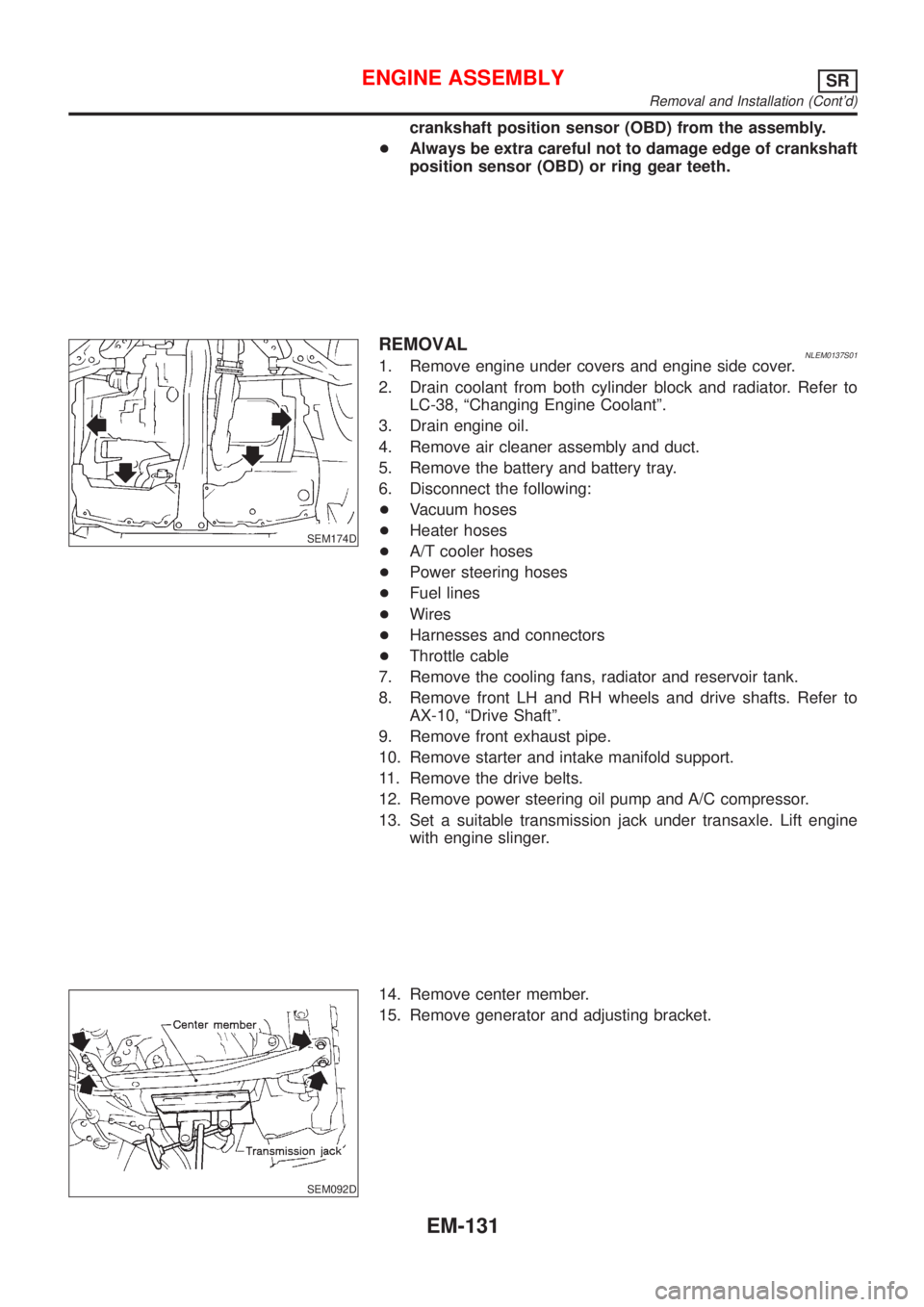
REMOVALNLEM0137S011. Remove engine under covers and engine side cover.
2. Drain coolant from both cylinder block and radiator. Refer to
LC-38, ªChanging Engine Coolantº.
3. Drain engine oil.
4. Remove air cleaner assembly and duct.
5. Remove the battery and battery tray.
6. Disconnect the following:
+Vacuum hoses
+Heater hoses
+A/T cooler hoses
+Power steering hoses
+Fuel lines
+Wires
+Harnesses and connectors
+Throttle cable
7. Remove the cooling fans, radiator and reservoir tank.
8. Remove front LH and RH wheels and drive shafts. Refer to
AX-10, ªDrive Shaftº.
9. Remove front exhaust pipe.
10. Remove starter and intake manifold support.
11. Remove the drive belts.
12. Remove power steering oil pump and A/C compressor.
13. Set a suitable transmission jack under transaxle. Lift engine
with engine slinger.
SEM092D
14. Remove center member.
15. Remove generator and adjusting bracket.
ENGINE ASSEMBLYSR
Removal and Installation (Cont'd)
EM-131
Page 2450 of 3051
Removal and InstallationNLEM0102
JEM265G
PREPARATIVE WORKNLEM0102S01Remove the following parts.
+Engine coolant (drain)
Refer to LC-59, ªChanging Engine Coolantº.
+Air duct, air inlet pipe
+Water inlet pipe
+Catalytic converter
+Exhaust manifold cover
+Insulator
+Each wiring and piping (disconnect/move)
JEM266G
EXHAUST MANIFOLD AND TURBOCHARGERNLEM0102S02RemovalNLEM0102S0201+Loosen exhaust manifold mounting nuts in the reverse order
specified in the figure.
+Rotate the exhaust manifold and turbocharger assembly so
that the rear side (EGR tube mounting side) faces upward. And
then pull out the assembly from between the engine and the
air conditioning piping.
CAUTION:
Be careful not to deform each turbocharger piping when pull-
ing out the assembly.
EXHAUST MANIFOLD, TURBOCHARGERYD
Removal and Installation
EM-193
Page 2451 of 3051
InstallationNLEM0102S0202+When a stud bolt is pulled out, tighten it to the following torque:
: 18 - 21 N´m (1.8 - 2.2 kg-m, 13 - 15 ft-lb)
+Tighten the exhaust manifold mounting nuts in the following
procedure:
a) Tighten the nuts in the order specified in the figure.
b) Re-tighten the nuts 1 to 4.
EXHAUST MANIFOLD GASKETNLEM0102S03InstallationNLEM0102S0301Install the gasket so that the alignment protrusion faces the No. 4
port.
Disassembly and AssemblyNLEM0103
SEM268G
TURBOCHARGERNLEM0103S01DisassemblyNLEM0103S0101After applying penetration lubricant (Lucen, etc.) to the mounting
nuts, check for the penetration of the lubricant, and then loosen the
nuts to remove.
EXHAUST MANIFOLD, TURBOCHARGERYD
Removal and Installation (Cont'd)
EM-194