2001 NISSAN ALMERA TINO fuel pump
[x] Cancel search: fuel pumpPage 1073 of 3051
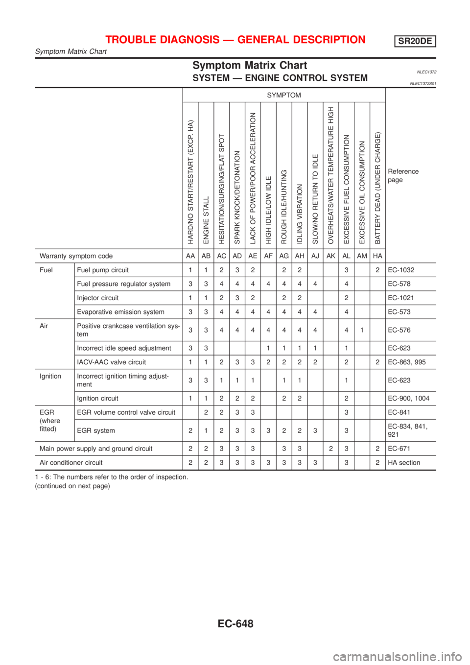
Symptom Matrix ChartNLEC1372SYSTEM Ð ENGINE CONTROL SYSTEMNLEC1372S01
SYMPTOM
Reference
page
HARD/NO START/RESTART (EXCP. HA)
ENGINE STALL
HESITATION/SURGING/FLAT SPOT
SPARK KNOCK/DETONATION
LACK OF POWER/POOR ACCELERATION
HIGH IDLE/LOW IDLE
ROUGH IDLE/HUNTING
IDLING VIBRATION
SLOW/NO RETURN TO IDLE
OVERHEATS/WATER TEMPERATURE HIGH
EXCESSIVE FUEL CONSUMPTION
EXCESSIVE OIL CONSUMPTION
BATTERY DEAD (UNDER CHARGE)
Warranty symptom code AA AB AC AD AE AF AG AH AJ AK AL AM HA
Fuel Fuel pump circuit11232 22 3 2EC-1032
Fuel pressure regulator system334444444 4EC-578
Injector circuit11232 22 2EC-1021
Evaporative emission system334444444 4EC-573
Air Positive crankcase ventilation sys-
tem334444444 41EC-576
Incorrect idle speed adjustment 3 31111 1EC-623
IACV-AAC valve circuit112332222 2 2EC-863, 995
Ignition Incorrect ignition timing adjust-
ment33111 11 1EC-623
Ignition circuit11222 22 2EC-900, 1004
EGR
(where
fitted)EGR volume control valve circuit2233 3EC-841
EGR system212333223 3EC-834, 841,
921
Main power supply and ground circuit22333 33 23 2EC-671
Air conditioner circuit223333333 3 2HAsection
1 - 6: The numbers refer to the order of inspection.
(continued on next page)
TROUBLE DIAGNOSIS Ð GENERAL DESCRIPTIONSR20DE
Symptom Matrix Chart
EC-648
Page 1076 of 3051
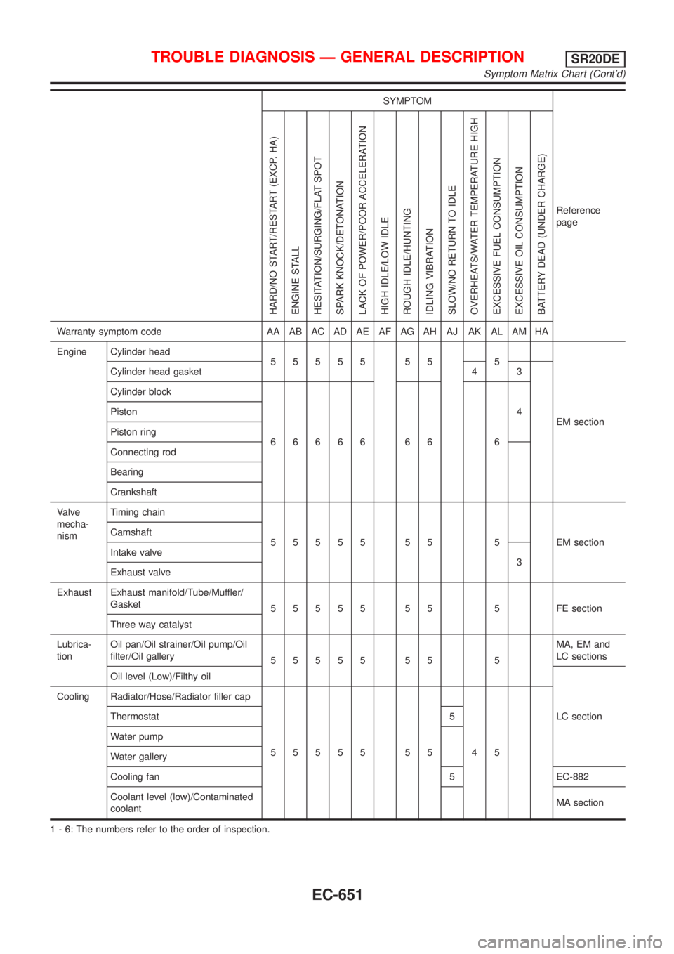
SYMPTOM
Reference
page
HARD/NO START/RESTART (EXCP. HA)
ENGINE STALL
HESITATION/SURGING/FLAT SPOT
SPARK KNOCK/DETONATION
LACK OF POWER/POOR ACCELERATION
HIGH IDLE/LOW IDLE
ROUGH IDLE/HUNTING
IDLING VIBRATION
SLOW/NO RETURN TO IDLE
OVERHEATS/WATER TEMPERATURE HIGH
EXCESSIVE FUEL CONSUMPTION
EXCESSIVE OIL CONSUMPTION
BATTERY DEAD (UNDER CHARGE)
Warranty symptom code AA AB AC AD AE AF AG AH AJ AK AL AM HA
Engine Cylinder head
55555 55 5
EM section Cylinder head gasket 4 3
Cylinder block
66666 66 64 Piston
Piston ring
Connecting rod
Bearing
Crankshaft
Valve
mecha-
nismTiming chain
55555 55 5 EMsection Camshaft
Intake valve
3
Exhaust valve
Exhaust Exhaust manifold/Tube/Muffler/
Gasket
55555 55 5 FEsection
Three way catalyst
Lubrica-
tionOil pan/Oil strainer/Oil pump/Oil
filter/Oil gallery
55555 55 5MA, EM and
LC sections
Oil level (Low)/Filthy oil
LC section Cooling Radiator/Hose/Radiator filler cap
55555 55 45 Thermostat 5
Water pump
Water gallery
Cooling fan 5 EC-882
Coolant level (low)/Contaminated
coolantMA section
1 - 6: The numbers refer to the order of inspection.
TROUBLE DIAGNOSIS Ð GENERAL DESCRIPTIONSR20DE
Symptom Matrix Chart (Cont'd)
EC-651
Page 1077 of 3051
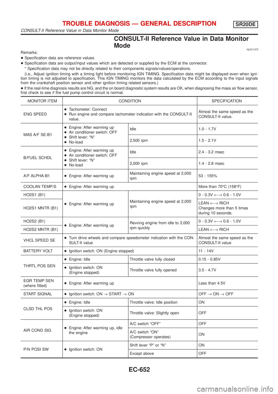
CONSULT-II Reference Value in Data Monitor
Mode
NLEC1373Remarks:
+Specification data are reference values.
+Specification data are output/input values which are detected or supplied by the ECM at the connector.
* Specification data may not be directly related to their components signals/values/operations.
(i.e., Adjust ignition timing with a timing light before monitoring IGN TIMING. Specification data might be displayed even when igni-
tion timing is not adjusted to specification. This IGN TIMING monitors the data calculated by the ECM according to the input signals
from the crankshaft position sensor and other ignition timing related sensors.)
+If the real-time diagnosis results are NG, and the on board diagnostic system results are OK, when diagnosing the mass air flow sensor,
first check to see if the fuel pump control circuit is normal.
MONITOR ITEM CONDITION SPECIFICATION
ENG SPEED+Tachometer: Connect
+Run engine and compare tachometer indication with the CONSULT-II
value.Almost the same speed as the
CONSULT-II value.
MAS A/F SE-B1+Engine: After warming up
+Air conditioner switch: OFF
+Shift lever: ªNº
+No-loadIdle 1.0 - 1.7V
2,500 rpm 1.5 - 2.1V
B/FUEL SCHDL+Engine: After warming up
+Air conditioner switch: OFF
+Shift lever: ªNº
+No-loadIdle 2.4 - 3.2 msec
2,000 rpm 1.4 - 2.8 msec
A/F ALPHA-B1+Engine: After warming upMaintaining engine speed at 2,000
rpm53 - 155%
COOLAN TEMP/S+Engine: After warming up More than 70ÉC (158ÉF)
HO2S1 (B1)
+Engine: After warming upMaintaining engine speed at 2,000
rpm0 - 0.3V¨0.6 - 1.0V
HO2S1 MNTR (B1)LEAN¨RICH
Changes more than 5 times
during 10 seconds.
HO2S2 (B1)
+Engine: After warming upRevving engine from idle to 3,000
rpm quickly0 - 0.3V¨0.6 - 1.0V
HO2S2 MNTR (B1)LEAN¨RICH
VHCL SPEED SE+Turn drive wheels and compare speedometer indication with the CON-
SULT-II valueAlmost the same speed as the
CONSULT-II value
BATTERY VOLT+Ignition switch: ON (Engine stopped) 11 - 14V
THRTL POS SEN+Engine: Idle Throttle valve fully closed 0.15 - 0.85V
+Ignition switch: ON
(Engine stopped)Throttle valve fully opened 3.5 - 4.7V
EGR TEMP SEN
(where fitted)+Engine: After warming up Less than 4.5V
START SIGNAL+Ignition switch: ON®START®ON OFF®ON®OFF
CLSD THL POS+Engine: Idle Throttle valve: Idle position ON
+Ignition switch: ON
(Engine stopped)Throttle valve: Slightly open OFF
AIR COND SIG+Engine: After warming up, idle
the engineA/C switch ªOFFº OFF
A/C switch ªONº
(Compressor operates)ON
P/N POSI SW+Ignition switch: ONShift lever ªPº or ªNº ON
Except above OFF
TROUBLE DIAGNOSIS Ð GENERAL DESCRIPTIONSR20DE
CONSULT-II Reference Value in Data Monitor Mode
EC-652
Page 1078 of 3051
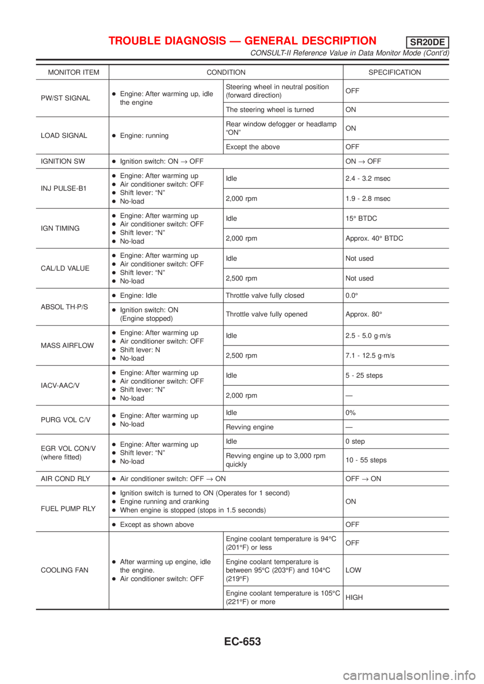
MONITOR ITEM CONDITION SPECIFICATION
PW/ST SIGNAL+Engine: After warming up, idle
the engineSteering wheel in neutral position
(forward direction)OFF
The steering wheel is turned ON
LOAD SIGNAL+Engine: runningRear window defogger or headlamp
ªONºON
Except the above OFF
IGNITION SW+Ignition switch: ON®OFF ON®OFF
INJ PULSE-B1+Engine: After warming up
+Air conditioner switch: OFF
+Shift lever: ªNº
+No-loadIdle 2.4 - 3.2 msec
2,000 rpm 1.9 - 2.8 msec
IGN TIMING+Engine: After warming up
+Air conditioner switch: OFF
+Shift lever: ªNº
+No-loadIdle 15É BTDC
2,000 rpm Approx. 40É BTDC
CAL/LD VALUE+Engine: After warming up
+Air conditioner switch: OFF
+Shift lever: ªNº
+No-loadIdle Not used
2,500 rpm Not used
ABSOL TH´P/S+Engine: Idle Throttle valve fully closed 0.0É
+Ignition switch: ON
(Engine stopped)Throttle valve fully opened Approx. 80É
MASS AIRFLOW+Engine: After warming up
+Air conditioner switch: OFF
+Shift lever: N
+No-loadIdle 2.5 - 5.0 g´m/s
2,500 rpm 7.1 - 12.5 g´m/s
IACV-AAC/V+Engine: After warming up
+Air conditioner switch: OFF
+Shift lever: ªNº
+No-loadIdle 5 - 25 steps
2,000 rpm Ð
PURG VOL C/V+Engine: After warming up
+No-loadIdle 0%
Revving engine Ð
EGR VOL CON/V
(where fitted)+Engine: After warming up
+Shift lever: ªNº
+No-loadIdle 0 step
Revving engine up to 3,000 rpm
quickly10 - 55 steps
AIR COND RLY+Air conditioner switch: OFF®ON OFF®ON
FUEL PUMP RLY+Ignition switch is turned to ON (Operates for 1 second)
+Engine running and cranking
+When engine is stopped (stops in 1.5 seconds)ON
+Except as shown above OFF
COOLING FAN+After warming up engine, idle
the engine.
+Air conditioner switch: OFFEngine coolant temperature is 94ÉC
(201ÉF) or lessOFF
Engine coolant temperature is
between 95ÉC (203ÉF) and 104ÉC
(219ÉF)LOW
Engine coolant temperature is 105ÉC
(221ÉF) or moreHIGH
TROUBLE DIAGNOSIS Ð GENERAL DESCRIPTIONSR20DE
CONSULT-II Reference Value in Data Monitor Mode (Cont'd)
EC-653
Page 1085 of 3051
![NISSAN ALMERA TINO 2001 Service Repair Manual TERMI-
NAL
NO.WIRE
COLORITEM CONDITION DATA (DC Voltage)
14 PEVAP canister purge
volume control valve
(ON/OFF duty)[Engine is running]
+Warm-up condition
+Idle speedBATTERY VOLTAGE
(11 - 14V)
[Engine NISSAN ALMERA TINO 2001 Service Repair Manual TERMI-
NAL
NO.WIRE
COLORITEM CONDITION DATA (DC Voltage)
14 PEVAP canister purge
volume control valve
(ON/OFF duty)[Engine is running]
+Warm-up condition
+Idle speedBATTERY VOLTAGE
(11 - 14V)
[Engine](/manual-img/5/57352/w960_57352-1084.png)
TERMI-
NAL
NO.WIRE
COLORITEM CONDITION DATA (DC Voltage)
14 PEVAP canister purge
volume control valve
(ON/OFF duty)[Engine is running]
+Warm-up condition
+Idle speedBATTERY VOLTAGE
(11 - 14V)
[Engine is running]
+Warm-up condition
+Engine speed is about 2,000 rpm5 - 12V
SEF975W
19 BR/W CVT signal No. 5[Engine is running]
+Idle speedApproximately 7.5V
21 B/P Fuel pump relay[Ignition switch ªONº]
+For 1 second after turning ignition switch ªONº
[Engine is running]0-1V
[Ignition switch ªONº]
+More than 1 second after turning ignition
switch ªONºBATTERY VOLTAGE
(11 - 14V)
22 OR/L Malfunction indicator[Ignition switch ªONº]0-1V
[Engine is running]
+Idle speedBATTERY VOLTAGE
(11 - 14V)
23 L Air conditioner relay[Engine is running]
+Both A/C switch and blower switch are ªONºApproximately 0V
[Engine is running]
+A/C switch is ªOFFºBATTERY VOLTAGE
(11 - 14V)
31 W/GECM relay (Self shut-
off)[Ignition switch ªOFFº]
+For a few seconds after turning ignition switch
ªOFFº0-1V
[Ignition switch ªOFFº]
+A few seconds passed after turning ignition
switch ªOFFºBATTERY VOLTAGE
(11 - 14V)
32 L/OR Tachometer[Engine is running]
+Warm-up condition
+Idle speedApproximately 10.5V
SEF973W
[Engine is running]
+Engine speed is 2,000 rpmApproximately 10.5V
SEF974W
TROUBLE DIAGNOSIS Ð GENERAL DESCRIPTIONSR20DE
ECM Terminals and Reference Value (Cont'd)
EC-660
Page 1222 of 3051
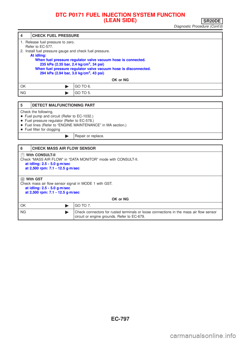
4 CHECK FUEL PRESSURE
1. Release fuel pressure to zero.
Refer to EC-577.
2. Install fuel pressure gauge and check fuel pressure.
At idling:
When fuel pressure regulator valve vacuum hose is connected.
235 kPa (2.35 bar, 2.4 kg/cm
2, 34 psi)
When fuel pressure regulator valve vacuum hose is disconnected.
294 kPa (2.94 bar, 3.0 kg/cm
2, 43 psi)
OK or NG
OK©GO TO 6.
NG©GO TO 5.
5 DETECT MALFUNCTIONING PART
Check the following.
+Fuel pump and circuit (Refer to EC-1032.)
+Fuel pressure regulator (Refer to EC-578.)
+Fuel lines (Refer to ªENGINE MAINTENANCEº in MA section.)
+Fuel filter for clogging
©Repair or replace.
6 CHECK MASS AIR FLOW SENSOR
With CONSULT-II
Check ªMASS AIR FLOWº in ªDATA MONITORº mode with CONSULT-II.
at idling: 2.5 - 5.0 g´m/sec
at 2,500 rpm: 7.1 - 12.5 g´m/sec
With GST
Check mass air flow sensor signal in MODE 1 with GST.
at idling: 2.5 - 5.0 g´m/sec
at 2,500 rpm: 7.1 - 12.5 g´m/sec
OK or NG
OK©GO TO 7.
NG©Check connectors for rusted terminals or loose connections in the mass air flow sensor
circuit or engine grounds. Refer to EC-679.
DTC P0171 FUEL INJECTION SYSTEM FUNCTION
(LEAN SIDE)
SR20DE
Diagnostic Procedure (Cont'd)
EC-797
Page 1230 of 3051
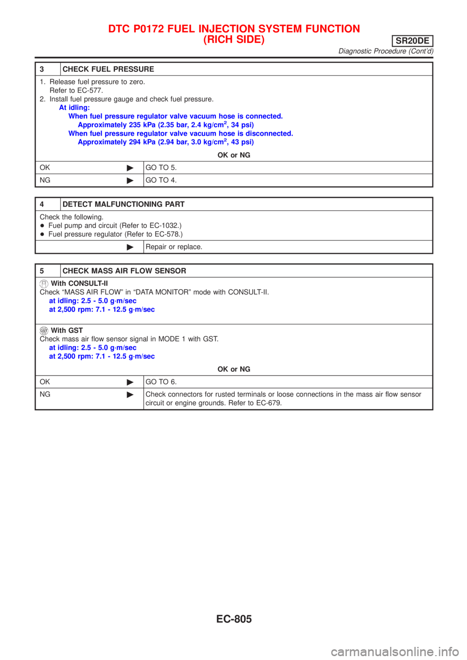
3 CHECK FUEL PRESSURE
1. Release fuel pressure to zero.
Refer to EC-577.
2. Install fuel pressure gauge and check fuel pressure.
At idling:
When fuel pressure regulator valve vacuum hose is connected.
Approximately 235 kPa (2.35 bar, 2.4 kg/cm
2, 34 psi)
When fuel pressure regulator valve vacuum hose is disconnected.
Approximately 294 kPa (2.94 bar, 3.0 kg/cm
2, 43 psi)
OK or NG
OK©GO TO 5.
NG©GO TO 4.
4 DETECT MALFUNCTIONING PART
Check the following.
+Fuel pump and circuit (Refer to EC-1032.)
+Fuel pressure regulator (Refer to EC-578.)
©Repair or replace.
5 CHECK MASS AIR FLOW SENSOR
With CONSULT-II
Check ªMASS AIR FLOWº in ªDATA MONITORº mode with CONSULT-II.
at idling: 2.5 - 5.0 g´m/sec
at 2,500 rpm: 7.1 - 12.5 g´m/sec
With GST
Check mass air flow sensor signal in MODE 1 with GST.
at idling: 2.5 - 5.0 g´m/sec
at 2,500 rpm: 7.1 - 12.5 g´m/sec
OK or NG
OK©GO TO 6.
NG©Check connectors for rusted terminals or loose connections in the mass air flow sensor
circuit or engine grounds. Refer to EC-679.
DTC P0172 FUEL INJECTION SYSTEM FUNCTION
(RICH SIDE)
SR20DE
Diagnostic Procedure (Cont'd)
EC-805
Page 1238 of 3051
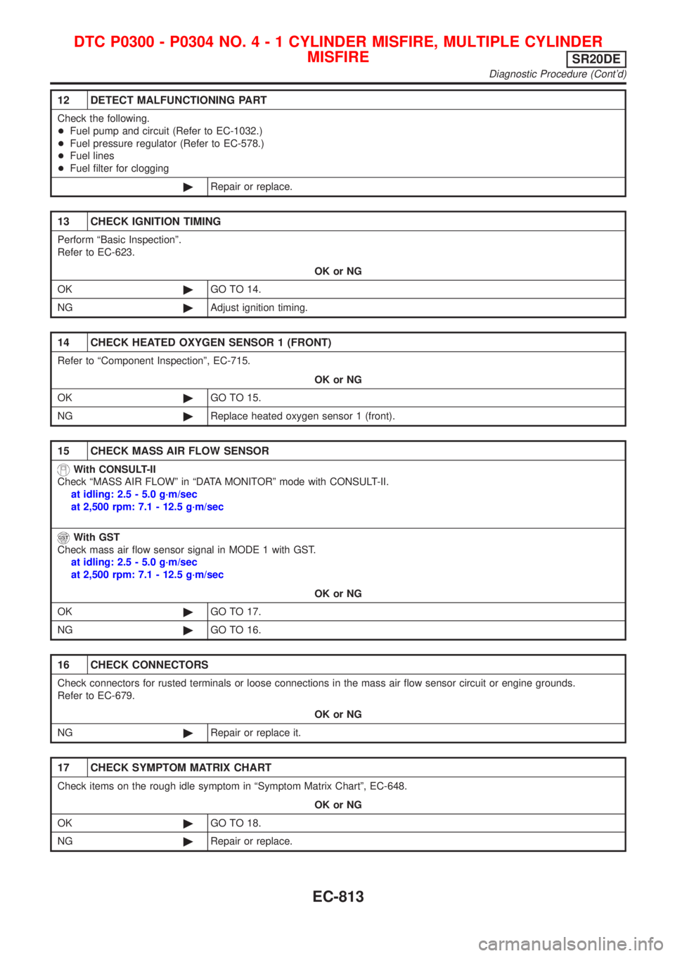
12 DETECT MALFUNCTIONING PART
Check the following.
+Fuel pump and circuit (Refer to EC-1032.)
+Fuel pressure regulator (Refer to EC-578.)
+Fuel lines
+Fuel filter for clogging
©Repair or replace.
13 CHECK IGNITION TIMING
Perform ªBasic Inspectionº.
Refer to EC-623.
OK or NG
OK©GO TO 14.
NG©Adjust ignition timing.
14 CHECK HEATED OXYGEN SENSOR 1 (FRONT)
Refer to ªComponent Inspectionº, EC-715.
OK or NG
OK©GO TO 15.
NG©Replace heated oxygen sensor 1 (front).
15 CHECK MASS AIR FLOW SENSOR
With CONSULT-II
Check ªMASS AIR FLOWº in ªDATA MONITORº mode with CONSULT-II.
at idling: 2.5 - 5.0 g´m/sec
at 2,500 rpm: 7.1 - 12.5 g´m/sec
With GST
Check mass air flow sensor signal in MODE 1 with GST.
at idling: 2.5 - 5.0 g´m/sec
at 2,500 rpm: 7.1 - 12.5 g´m/sec
OK or NG
OK©GO TO 17.
NG©GO TO 16.
16 CHECK CONNECTORS
Check connectors for rusted terminals or loose connections in the mass air flow sensor circuit or engine grounds.
Refer to EC-679.
OK or NG
NG©Repair or replace it.
17 CHECK SYMPTOM MATRIX CHART
Check items on the rough idle symptom in ªSymptom Matrix Chartº, EC-648.
OK or NG
OK©GO TO 18.
NG©Repair or replace.
DTC P0300 - P0304 NO.4-1CYLINDER MISFIRE, MULTIPLE CYLINDER
MISFIRE
SR20DE
Diagnostic Procedure (Cont'd)
EC-813