Page 271 of 3051
SBR892
6. Install cup in the specified direction.
SBR755E
7. Install adjuster, bearing, washers and snap ring A with a suit-
able tool.
SBR646
8. Insert piston seal into groove on cylinder body.
9. With piston boot fitted to piston, insert piston boot into groove
on cylinder body and fit piston by turning it clockwise with long
nose pliers, or suitable tool.
SBR767E
10. Fit toggle lever, return spring and cable guide.
NBR374
11. Adjust the piston to the right angle as shown in the figure.
REAR DISC BRAKE (CAM & STRUT TYPE)
Assembly (Cont’d)
BR-34
Page 273 of 3051

ComponentNLBR0150
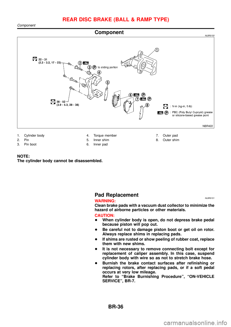
NBR422
1. Cylinder body
2. Pin
3. Pin boot4. Torque member
5. Inner shim
6. Inner pad7. Outer pad
8. Outer shim
NOTE:
The cylinder body cannot be disassembled.
Pad ReplacementNLBR0151WARNING:
Clean brake pads with a vacuum dust collector to minimize the
hazard of airborne particles or other materials.
CAUTION:
+When cylinder body is open, do not depress brake pedal
because piston will pop out.
+Be careful not to damage piston boot or get oil on rotor.
Always replace shims in replacing pads.
+If shims are rusted or show peeling of rubber coat, replace
them with new shims.
+It is not necessary to remove connecting bolt except for
replacement of caliper assembly. In this case, suspend
cylinder body with wire so as not to stretch brake hose.
+Burnish the brake contact surfaces after refinishing or
replacing rotors, after replacing pads, or if a soft pedal
occurs at very low mileage.
Refer to“Brake Burnishing Procedure”,“ON-VEHICLE
SERVICE”, BR-7.
REAR DISC BRAKE (BALL & RAMP TYPE)
Component
BR-36
Page 275 of 3051

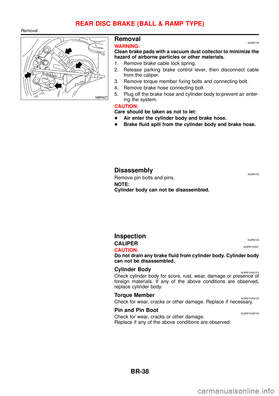
NBR427
RemovalNLBR0152WARNING:
Clean brake pads with a vacuum dust collector to minimize the
hazard of airborne particles or other materials.
1. Remove brake cable lock spring.
2. Release parking brake control lever, then disconnect cable
from the caliper.
3. Remove torque member fixing bolts and connecting bolt.
4. Remove brake hose connecting bolt.
5. Plug off the brake hose and cylinder body to prevent air enter-
ing the system.
CAUTION:
Care should be taken as not to let:
+Air enter the cylinder body and brake hose.
+Brake fluid spill from the cylinder body and brake hose.
DisassemblyNLBR0153Remove pin bolts and pins.
NOTE:
Cylinder body can not be disassembled.
InspectionNLBR0154CALIPERNLBR0154S01CAUTION:
Do not drain any brake fluid from cylinder body. Cylinder body
can not be disassembled.
Cylinder BodyNLBR0154S0101Check cylinder body for score, rust, wear, damage or presence of
foreign materials. If any of the above conditions are observed,
replace cylinder body.
Torque MemberNLBR0154S0102Check for wear, cracks or other damage. Replace if necessary.
Pin and Pin BootNLBR0154S0104Check for wear, cracks or other damage.
Replace if any of the above conditions are observed.
REAR DISC BRAKE (BALL & RAMP TYPE)
Removal
BR-38
Page 1914 of 3051
RemovalNLEL0060S02011. Remove wiper arms and cowl top cover.
2. Remove wiper motor connector.
3. Remove 5 screws and 3 nuts.
4. Remove wiper linkage.
Be careful not to break ball joint rubber boot.
InstallationNLEL0060S0202+Grease ball joint portion before installation.
1. Installation is the reverse order of removal.
GEL013-A
Washer Nozzle AdjustmentNLEL0061+Adjust washer nozzle with suitable tool as shown in the figure
at left.
Adjustable range:±10É (In any direction)
NEL720
Unit: mm (in)
*1 646.9 (25.47) *5 230.1 (9.06)
*2 470.2 (18.51) *6 16.8 (0.66)
*3 332.9 (13.11) *7 356.5 (14.04)
*4 550.9 (21.69) *8 394.8 (15.54)
*: The diameters of these circles are less than 80 mm (3.15 in).
Washer Tube LayoutNLEL0062
NEL725
FRONT WIPER AND WASHER
Removal and Installation (Cont'd)
EL-183
Page 2346 of 3051

SMA273C
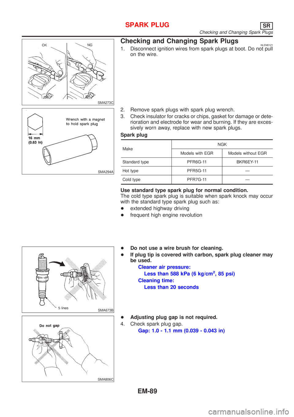
Checking and Changing Spark PlugsNLEM01211. Disconnect ignition wires from spark plugs at boot. Do not pull
on the wire.
SMA294A
2. Remove spark plugs with spark plug wrench.
3. Check insulator for cracks or chips, gasket for damage or dete-
rioration and electrode for wear and burning. If they are exces-
sively worn away, replace with new spark plugs.
Spark plug
MakeNGK
Models with EGR Models without EGR
Standard type PFR6G-11 BKR6EY-11
Hot type PFR5G-11 Ð
Cold type PFR7G-11 Ð
Use standard type spark plug for normal condition.
The cold type spark plug is suitable when spark knock may occur
with the standard type spark plug such as:
+extended highway driving
+frequent high engine revolution
SMA673B
+Do not use a wire brush for cleaning.
+If plug tip is covered with carbon, spark plug cleaner may
be used.
Cleaner air pressure:
Less than 588 kPa (6 kg/cm
2, 85 psi)
Cleaning time:
Less than 20 seconds
SMA806C
+Adjusting plug gap is not required.
4. Check spark plug gap.
Gap: 1.0 - 1.1 mm (0.039 - 0.043 in)
SPARK PLUGSR
Checking and Changing Spark Plugs
EM-89
Page 2804 of 3051
SMT563AA
Replacing Oil SealNLMT0035DIFFERENTIAL OIL SEALNLMT0035S011. Drain gear oil from transaxle.
2. Remove drive shafts. Refer to AX-11, “Removal”.
3. Remove differential oil seal.
SMT564AB
4. Install differential oil seal.
+Apply multi-purpose grease to seal lip of oil seal before
installing.
5. Install drive shafts. Refer to AX-11, “Installation”.
SMT926DA
SMT927D
+Install differential oil seal so that dimension“A”and“B”
are within specifications.
Unit: mm (in)
Item Model A B
DimensionRS5F70A
�0.5 (�0.020) to 0.5 (0.020)
RS5F50A
SMT143DC
STRIKING ROD OIL SEALNLMT0035S021. Remove transaxle control rod from yoke.
2. Remove retaining pin of yoke.
+Be careful not to damage boot.
ON-VEHICLE SERVICE
Replacing Oil Seal
MT-15
Page 2812 of 3051
NLMT0038
ComponentsNLMT0038S01
NMT133
1. Control lever knob
2. Boot
3. Control lever socket
4. Control lever
5. Bearing seat spring
6. Seat
7. Bush
8. O-ring9. Hand lever socket
10. Plate bolt
11. Transaxle hole cover
12. Mass damper
13. Holder bracket
14. Return spring rubber
15. Return spring
16. Control rod17. Bush
18. Collar
19. Bush
20. Collar
21. Support rod
22. Plate
23. Support rod bracket
TRANSAXLE GEAR CONTROL
Components
MT-23
Page 2813 of 3051
NLMT0054
Case ComponentsNLMT0054S02
SMT942D
1. Clutch housing
2. Dust seal
3. Oil pocket
4. Check plug
5. Input shaft oil seal
6. Oil channel
7. Mainshaft front bearing
8. Bearing retainer
9. Bush
10. Reverse idler gear front thrust
washer
11. Reverse idler gear
12. Reverse idler gear bearing
13. Reverse idler gear rear thrust
washer14. O-ring
15. Reverse idler gear shaft
16. Snap ring
17. Reverse switch
18. Filler plug
19. Side cover gasket
20. Side cover
21. Welch plug
22. Mainshaft bearing snap ring
23. Mainshaft rear bearing adjusting
shim
24. O-ring
25. Rear cover26. Differential oil seal
27. Drain plug
28. PNP switch
29. Transmission case
30. Oil gutter
31. Welch plug
32. Magnet
33. Boot
34. Striking rod oil seal
35. Welch plug
36. Differential oil seal
37. O-ring
38. Speedometer pinion
OVERHAULRS5F70A
Case Components
MT-24