2001 NISSAN ALMERA TINO air condition
[x] Cancel search: air conditionPage 1353 of 3051
System DescriptionNLEC1641The malfunction information related to CVT is transferred through the line (circuit) from TCM (Transmission
Control Module) to ECM. Therefore, be sure to erase the malfunction information such as DTC not only in TCM
(Transmission Control Module) but also ECM after the CVT related repair.
ECM Terminals and Reference ValueNLEC1642Specification data are reference values and are measured between each terminal and ground.
CAUTION:
Do not use ECM ground terminals when measuring input/output voltage. Doing so may result in dam-
age to the ECM's transistor. Use a ground other than ECM terminals, such as the ground.
TERMI-
NAL
NO.WIRE
COLORITEM CONDITION DATA (DC Voltage)
91 PU CVT check signal[Ignition switch ªONº]0 - Approximately 5V
On Board Diagnosis LogicNLEC1643
DTC No. Malfunction is detected when ... Check Items (Possible Cause)
P1605+An incorrect signal from TCM (Transmission Control
Module) is sent to ECM.+Harness or connectors
[The communication line circuit between ECM
and TCM (Transmission Control Module) is open
or shorted.]
+Dead (Weak) battery
+TCM (Transmission Control Module)
SEF058Y
DTC Confirmation ProcedureNLEC1644NOTE:
If ªDTC CONFIRMATION PROCEDUREº has been previously
conducted, always turn ignition switch ªOFFº and wait at least 10
seconds before conducting the next test.
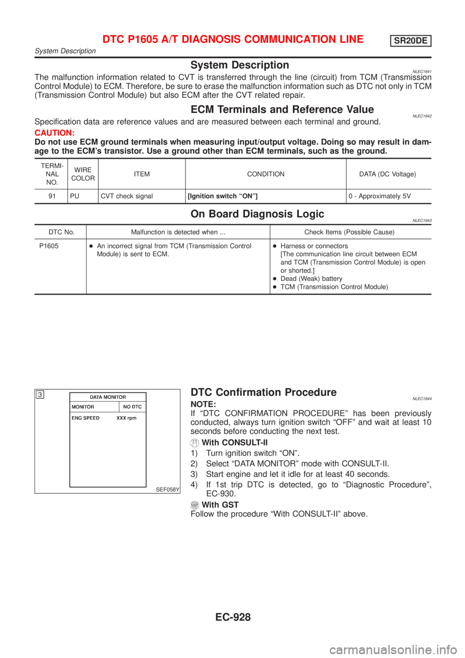
With CONSULT-II
1) Turn ignition switch ªONº.
2) Select ªDATA MONITORº mode with CONSULT-II.
3) Start engine and let it idle for at least 40 seconds.
4) If 1st trip DTC is detected, go to ªDiagnostic Procedureº,
EC-930.
With GST
Follow the procedure ªWith CONSULT-IIº above.
DTC P1605 A/T DIAGNOSIS COMMUNICATION LINESR20DE
System Description
EC-928
Page 1369 of 3051
SEF463R
SEF288D
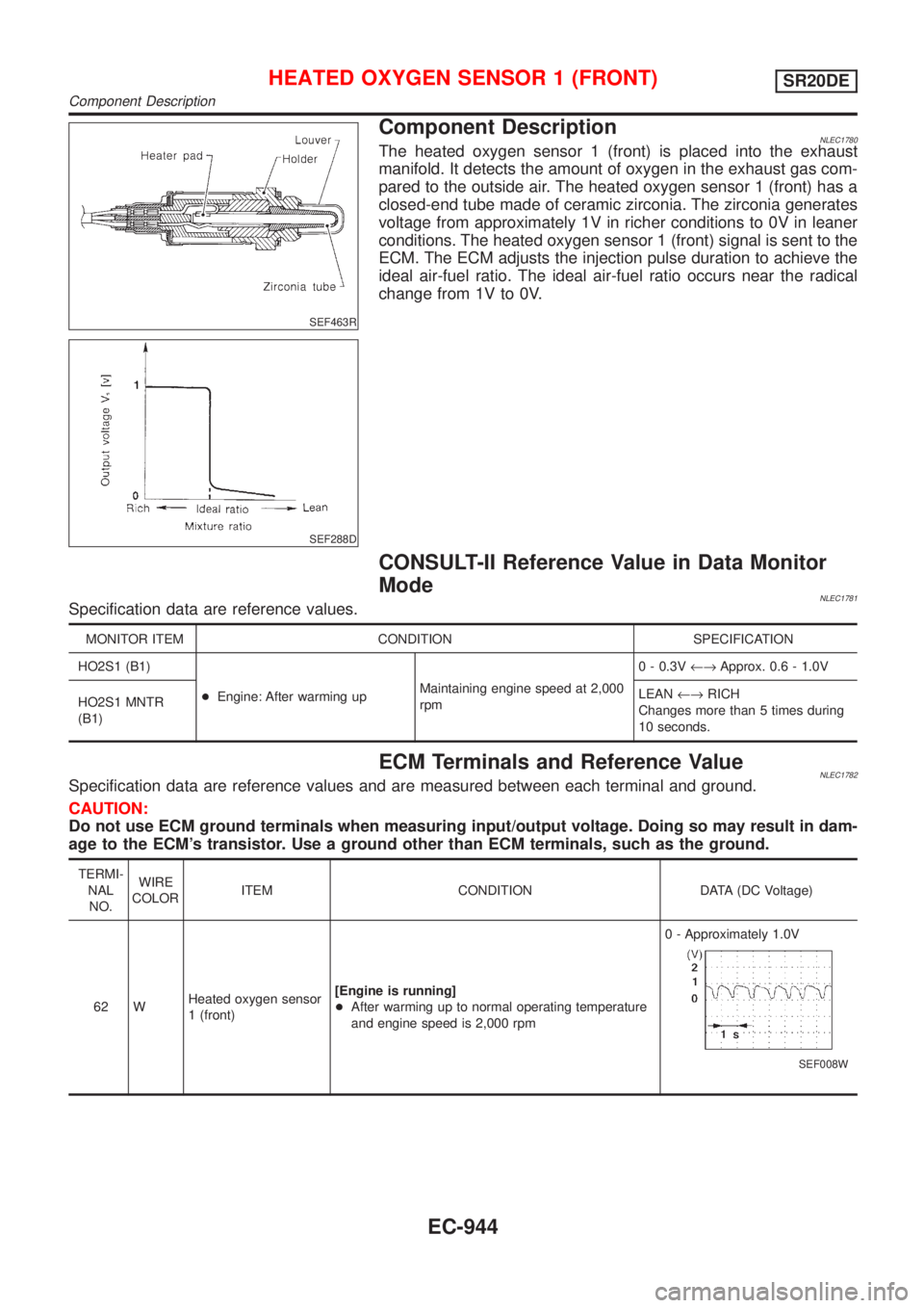
Component DescriptionNLEC1780The heated oxygen sensor 1 (front) is placed into the exhaust
manifold. It detects the amount of oxygen in the exhaust gas com-
pared to the outside air. The heated oxygen sensor 1 (front) has a
closed-end tube made of ceramic zirconia. The zirconia generates
voltage from approximately 1V in richer conditions to 0V in leaner
conditions. The heated oxygen sensor 1 (front) signal is sent to the
ECM. The ECM adjusts the injection pulse duration to achieve the
ideal air-fuel ratio. The ideal air-fuel ratio occurs near the radical
change from 1V to 0V.
CONSULT-II Reference Value in Data Monitor
Mode
NLEC1781Specification data are reference values.
MONITOR ITEM CONDITION SPECIFICATION
HO2S1 (B1)
+Engine: After warming upMaintaining engine speed at 2,000
rpm0 - 0.3V¨Approx. 0.6 - 1.0V
HO2S1 MNTR
(B1)LEAN¨RICH
Changes more than 5 times during
10 seconds.
ECM Terminals and Reference ValueNLEC1782Specification data are reference values and are measured between each terminal and ground.
CAUTION:
Do not use ECM ground terminals when measuring input/output voltage. Doing so may result in dam-
age to the ECM's transistor. Use a ground other than ECM terminals, such as the ground.
TERMI-
NAL
NO.WIRE
COLORITEM CONDITION DATA (DC Voltage)
62 WHeated oxygen sensor
1 (front)[Engine is running]
+After warming up to normal operating temperature
and engine speed is 2,000 rpm0 - Approximately 1.0V
SEF008W
HEATED OXYGEN SENSOR 1 (FRONT)SR20DE
Component Description
EC-944
Page 1381 of 3051
SEF327R
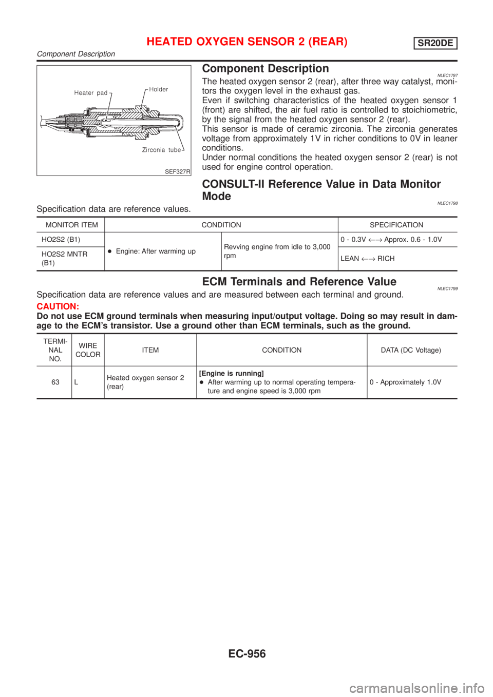
Component DescriptionNLEC1797The heated oxygen sensor 2 (rear), after three way catalyst, moni-
tors the oxygen level in the exhaust gas.
Even if switching characteristics of the heated oxygen sensor 1
(front) are shifted, the air fuel ratio is controlled to stoichiometric,
by the signal from the heated oxygen sensor 2 (rear).
This sensor is made of ceramic zirconia. The zirconia generates
voltage from approximately 1V in richer conditions to 0V in leaner
conditions.
Under normal conditions the heated oxygen sensor 2 (rear) is not
used for engine control operation.
CONSULT-II Reference Value in Data Monitor
Mode
NLEC1798Specification data are reference values.
MONITOR ITEM CONDITION SPECIFICATION
HO2S2 (B1)
+Engine: After warming upRevving engine from idle to 3,000
rpm0 - 0.3V¨Approx. 0.6 - 1.0V
HO2S2 MNTR
(B1)LEAN¨RICH
ECM Terminals and Reference ValueNLEC1799Specification data are reference values and are measured between each terminal and ground.
CAUTION:
Do not use ECM ground terminals when measuring input/output voltage. Doing so may result in dam-
age to the ECM's transistor. Use a ground other than ECM terminals, such as the ground.
TERMI-
NAL
NO.WIRE
COLORITEM CONDITION DATA (DC Voltage)
63 LHeated oxygen sensor 2
(rear)[Engine is running]
+After warming up to normal operating tempera-
ture and engine speed is 3,000 rpm0 - Approximately 1.0V
HEATED OXYGEN SENSOR 2 (REAR)SR20DE
Component Description
EC-956
Page 1400 of 3051
DescriptionNLEC1818SYSTEM DESCRIPTIONNLEC1818S01
Sensor Input Signal to ECMECM func-
tionActuator
Camshaft position sensor Engine speed
EGR vol-
ume controlEGR volume control valve Mass air flow sensor Amount of intake air
Engine coolant temperature sensor Engine coolant temperature
Ignition switch Start signal
Throttle position sensor Throttle position
Vehicle speed sensor Vehicle speed
Battery Battery voltage
Air conditioner switch Air conditioner operation
Power steering oil pressure switch Power steering load signal
Electrical load Electrical load signal
PNP switch Park/Neutral position signal
TCM (Transmission Control Module) Gear position, shifting signal
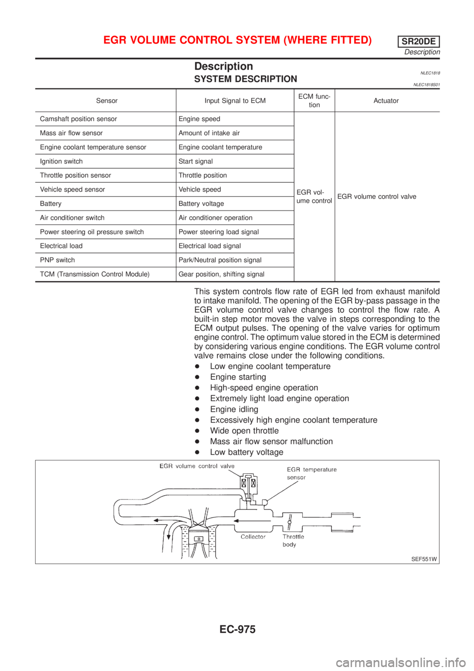
This system controls flow rate of EGR led from exhaust manifold
to intake manifold. The opening of the EGR by-pass passage in the
EGR volume control valve changes to control the flow rate. A
built-in step motor moves the valve in steps corresponding to the
ECM output pulses. The opening of the valve varies for optimum
engine control. The optimum value stored in the ECM is determined
by considering various engine conditions. The EGR volume control
valve remains close under the following conditions.
+Low engine coolant temperature
+Engine starting
+High-speed engine operation
+Extremely light load engine operation
+Engine idling
+Excessively high engine coolant temperature
+Wide open throttle
+Mass air flow sensor malfunction
+Low battery voltage
SEF551W
EGR VOLUME CONTROL SYSTEM (WHERE FITTED)SR20DE
Description
EC-975
Page 1401 of 3051
SEF552W
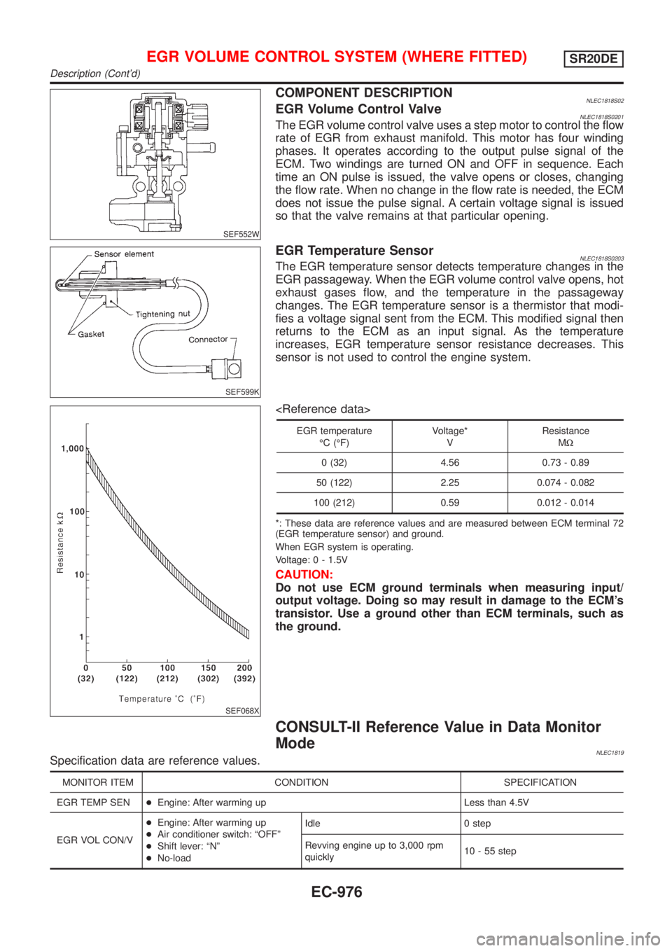
COMPONENT DESCRIPTIONNLEC1818S02EGR Volume Control ValveNLEC1818S0201The EGR volume control valve uses a step motor to control the flow
rate of EGR from exhaust manifold. This motor has four winding
phases. It operates according to the output pulse signal of the
ECM. Two windings are turned ON and OFF in sequence. Each
time an ON pulse is issued, the valve opens or closes, changing
the flow rate. When no change in the flow rate is needed, the ECM
does not issue the pulse signal. A certain voltage signal is issued
so that the valve remains at that particular opening.
SEF599K
EGR Temperature SensorNLEC1818S0203The EGR temperature sensor detects temperature changes in the
EGR passageway. When the EGR volume control valve opens, hot
exhaust gases flow, and the temperature in the passageway
changes. The EGR temperature sensor is a thermistor that modi-
fies a voltage signal sent from the ECM. This modified signal then
returns to the ECM as an input signal. As the temperature
increases, EGR temperature sensor resistance decreases. This
sensor is not used to control the engine system.
SEF068X
EGR temperature
ÉC (ÉF)Voltage*
VResistance
MW
0 (32) 4.56 0.73 - 0.89
50 (122) 2.25 0.074 - 0.082
100 (212) 0.59 0.012 - 0.014
*: These data are reference values and are measured between ECM terminal 72
(EGR temperature sensor) and ground.
When EGR system is operating.
Voltage: 0 - 1.5V
CAUTION:
Do not use ECM ground terminals when measuring input/
output voltage. Doing so may result in damage to the ECM's
transistor. Use a ground other than ECM terminals, such as
the ground.
CONSULT-II Reference Value in Data Monitor
Mode
NLEC1819Specification data are reference values.
MONITOR ITEM CONDITION SPECIFICATION
EGR TEMP SEN+Engine: After warming up Less than 4.5V
EGR VOL CON/V+Engine: After warming up
+Air conditioner switch: ªOFFº
+Shift lever: ªNº
+No-loadIdle 0 step
Revving engine up to 3,000 rpm
quickly10 - 55 step
EGR VOLUME CONTROL SYSTEM (WHERE FITTED)SR20DE
Description (Cont'd)
EC-976
Page 1411 of 3051
DescriptionNLEC1827SYSTEM DESCRIPTIONNLEC1827S01
Sensor Input Signal to ECMECM func-
tionActuator
Camshaft position sensor Engine speed
EVAP can-
ister purge
controlEVAP canister purge volume
control solenoid valve Mass air flow sensor Amount of intake air
Engine coolant temperature sensor Engine coolant temperature
Battery Battery voltage
Ignition switch Start signal
Closed throttle position switch Closed throttle position
Throttle position sensor Throttle position
Heated oxygen sensor 1 (front)Density of oxygen in exhaust gas
(Mixture ratio feedback signal)
Fuel tank temperature sensor Fuel temperature in fuel tank
Vehicle speed sensor Vehicle speed
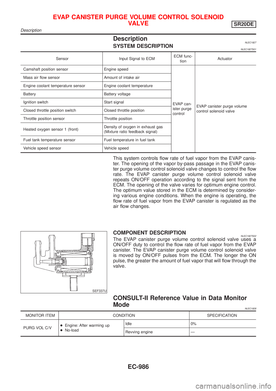
This system controls flow rate of fuel vapor from the EVAP canis-
ter. The opening of the vapor by-pass passage in the EVAP canis-
ter purge volume control solenoid valve changes to control the flow
rate. The EVAP canister purge volume control solenoid valve
repeats ON/OFF operation according to the signal sent from the
ECM. The opening of the valve varies for optimum engine control.
The optimum value stored in the ECM is determined by consider-
ing various engine conditions. When the engine is operating, the
flow rate of fuel vapor from the EVAP canister is regulated as the
air flow changes.
SEF337U
COMPONENT DESCRIPTIONNLEC1827S02The EVAP canister purge volume control solenoid valve uses a
ON/OFF duty to control the flow rate of fuel vapor from the EVAP
canister. The EVAP canister purge volume control solenoid valve
is moved by ON/OFF pulses from the ECM. The longer the ON
pulse, the greater the amount of fuel vapor that will flow through the
valve.
CONSULT-II Reference Value in Data Monitor
Mode
NLEC1828
MONITOR ITEM CONDITION SPECIFICATION
PURG VOL C/V+Engine: After warming up
+No-loadIdle 0%
Revving engine Ð
EVAP CANISTER PURGE VOLUME CONTROL SOLENOID
VALVE
SR20DE
Description
EC-986
Page 1416 of 3051
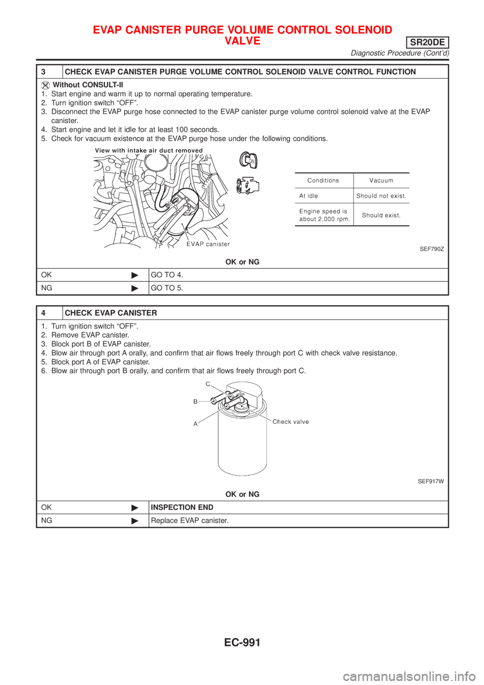
3 CHECK EVAP CANISTER PURGE VOLUME CONTROL SOLENOID VALVE CONTROL FUNCTION
Without CONSULT-II
1. Start engine and warm it up to normal operating temperature.
2. Turn ignition switch ªOFFº.
3. Disconnect the EVAP purge hose connected to the EVAP canister purge volume control solenoid valve at the EVAP
canister.
4. Start engine and let it idle for at least 100 seconds.
5. Check for vacuum existence at the EVAP purge hose under the following conditions.
SEF790Z
OK or NG
OK©GO TO 4.
NG©GO TO 5.
4 CHECK EVAP CANISTER
1. Turn ignition switch ªOFFº.
2. Remove EVAP canister.
3. Block port B of EVAP canister.
4. Blow air through port A orally, and confirm that air flows freely through port C with check valve resistance.
5. Block port A of EVAP canister.
6. Blow air through port B orally, and confirm that air flows freely through port C.
SEF917W
OK or NG
OK©INSPECTION END
NG©Replace EVAP canister.
EVAP CANISTER PURGE VOLUME CONTROL SOLENOID
VALVE
SR20DE
Diagnostic Procedure (Cont'd)
EC-991
Page 1419 of 3051
10 DETECT MALFUNCTIONING PART
Check the following.
+Harness connectors F60, F13
+Harness for open or short between EVAP canister purge volume control solenoid valve and ECM.
©Repair copen circuit or short to ground or short to power in harness or connectors.
11 CHECK EVAP CANISTER PURGE VOLUME CONTROL SOLENOID VALVE
Refer to ªComponent Inspectionº EC-994.
OK or NG
OK©GO TO 12.
NG©Replace EVAP canister purge volume control solenoid valve.
12 CHECK INTERMITTENT INCIDENT
Perform ªTROUBLE DIAGNOSIS FOR INTERMITTENT INCIDENTº, EC-670.
©INSPECTION END
SEF801Y
SEF661U
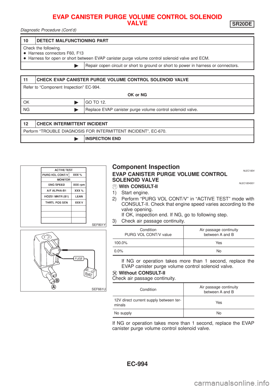
Component InspectionNLEC1834EVAP CANISTER PURGE VOLUME CONTROL
SOLENOID VALVE
NLEC1834S01With CONSULT-II
1) Start engine.
2) Perform ªPURG VOL CONT/Vº in ªACTIVE TESTº mode with
CONSULT-II. Check that engine speed varies according to the
valve opening.
If OK, inspection end. If NG, go to following step.
3) Check air passage continuity.
Condition
PURG VOL CONT/V valueAir passage continuity
between A and B
100.0% Yes
0.0% No
If NG or operation takes more than 1 second, replace the
EVAP canister purge volume control solenoid valve.
Without CONSULT-II
Check air passage continuity.
ConditionAir passage continuity
between A and B
12V direct current supply between ter-
minalsYe s
No supply No
If NG or operation takes more than 1 second, replace the EVAP
canister purge volume control solenoid valve.
EVAP CANISTER PURGE VOLUME CONTROL SOLENOID
VALVE
SR20DE
Diagnostic Procedure (Cont'd)
EC-994