2001 NISSAN ALMERA TINO fuel pump
[x] Cancel search: fuel pumpPage 2519 of 3051

SFE376A
7. Remove lock ring using a lock ring socket (SST).
SFE648A
8. Pull out the fuel level sensor unit and fuel pump.
+Do not damage the arm of the fuel level sensor unit and
fuel tank temperature sensor.
INSTALLATIONNLFE0007S02Installation is in reverse order of removal.
FUEL SYSTEMQG/SR
Fuel Pump, Fuel Level Sensor Unit and Fuel Filter (Cont’d)
FE-10
Page 2525 of 3051

JFE624A
INSTALLATIONNLFE0021S02+Install in the reverse order of removal.
+Replace the O-ring of the fuel level warning sensor with a new
one.
+Tighten the fuel filter so that the sealing face contacts the
packing, then retighten it manually by approximately 2/3 turn.
+After installation, operate the priming pump vertically to per-
form air bleeding.
Refer to FE-16,“Bleeding Fuel Filter”.
Bleeding Fuel FilterNLFE00231. After the repair, bleed air from the piping by pumping the prim-
ing pump up and down until it becomes heavy.
2. To start the engine, rotate the starter for a maximum of 30
seconds.
To start the engine more quickly, crank the engine while pump-
ing the priming pump (requires two workers).
3. If the engine does not start after rotating the starter for a maxi-
mum of 30 seconds, stop it once, and pump the priming pump
again until it becomes heavy.
4. Rotate the starter again until the engine starts running.
5. After the engine starts, let it idle for at least 1 minute to stabi-
lize the behavior.
+When air is bled completely, the pumping of the priming
pump suddenly becomes heavy. Stop the operation at that
time.
+If it is difficult to bleed air by the pumping of the priming
pump (the pumping of the priming pump does not become
heavy), disconnect the fuel supply hose between the fuel
filter and the injection pump. Then, perform the operation
described above, and make sure that fuel comes out. (Use
a pan, etc. so as not to spill fuel. Do not let fuel get on
engine and other parts.) After that, connect the hose, then
bleed air again.
+Start engine and let it idle for at least one minute after
performing air bleeding.
DEF017
Checking Priming PumpNLFE0024Before checking priming pump, make sure that fuel filter is
filled with fuel.
1. Disconnect fuel return hose.
Place a suitable container beneath hose end.
2. Pump priming pump and check that the fuel overflows from the
hose end. If not, replace priming pump.
FUEL SYSTEMYD
Changing Fuel Filter (Cont’d)
FE-16
Page 2531 of 3051

SFE376A
7. Remove lock ring using a lock ring socket (SST).
SFE648AA
8. Pull out the fuel level sensor unit and fuel pump.
+Do not damage the arm of the fuel level sensor unit.
INSTALLATIONNLFE0032S02Installation is in reverse order of removal.
FUEL SYSTEMYD
Fuel Level Sensor Unit (Cont’d)
FE-22
Page 2545 of 3051

Do not attempt to top up the fuel tank after the fuel pump nozzle
shuts off automatically. Continued refueling may cause fuel
overflow, resulting in fuel spray and possibly a fire.
WARNING:
To prevent ECM from storing the diagnostic trouble codes, do
not carelessly disconnect the harness connectors which are
related to the engine control system and TCM (Transmission
Control Module) system. The connectors should be discon-
nected only when working according to the WORK FLOW of
TROUBLE DIAGNOSES in EC and AT sections.
SGI787
PRECAUTIONS FOR MULTIPORT FUEL INJECTION
SYSTEM OR ENGINE CONTROL SYSTEM
NLGI0001S04+Before connecting or disconnecting any harness connector for
the multiport fuel injection system or ECM:
Turn ignition switch to“OFF”position.
Disconnect negative battery terminal.
Otherwise, there may be damage to ECM.
+Before disconnecting pressurized fuel line from fuel pump to
injectors, be sure to release fuel pressure.
+Be careful not to jar components such as ECM and mass air
flow sensor.
PRECAUTIONS FOR THREE WAY CATALYSTNLGI0001S05If a large amount of unburned fuel flows into the catalyst, the cata-
lyst temperature will be excessively high. To prevent this, follow the
instructions below:
+Use unleaded gasoline only. Leaded gasoline will seriously
damage the three way catalyst.
+When checking for ignition spark or measuring engine
compression, make tests quickly and only when necessary.
+Do not run engine when the fuel tank level is low, otherwise the
engine may misfire, causing damage to the catalyst.
Do not place the vehicle on flammable material. Keep flammable
material off the exhaust pipe and the three way catalyst.
SMA019D
PRECAUTIONS FOR HOSESNLGI0001S06Hose Removal and InstallationNLGI0001S0601+To prevent damage to rubber hose, do not pry off rubber hose
with tapered tool or screwdriver.
PRECAUTIONS
Precautions (Cont’d)
GI-6
Page 2589 of 3051

NEW TERMNEW ACRONYM /
ABBREVIATIONOLD TERM
Manifold absolute pressure MAP ***
Manifold absolute pressure/Barometric
pressure switch solenoid valveMAP/BARO switch solenoid valve ***
Manifold absolute pressure sensor MAPS ***
Manifold differential pressure MDP ***
Manifold differential pressure sensor MDPS ***
Manifold surface temperature MST ***
Manifold surface temperature sensor MSTS ***
Manifold vacuum zone MVZ ***
Manifold vacuum zone sensor MVZS ***
Mass air flow sensor MAFS Air flow meter
Mixture control solenoid valve MC solenoid valve Air-fuel ratio control solenoid valve
Multiport fuel injection system MFI system Fuel injection control
Neutral position switch *** Neutral switch
Nonvolatile random access memory NVRAM ***
On board diagnostic system OBD system Self-diagnoses
Open loop OL Open loop
Oxidation catalyst OC Catalyst
Oxidation catalytic converter system OC system ***
Oxygen sensor O2S Exhaust gas sensor
Park position switch *** Park switch
Park/neutral position switch PNP switch Park/neutral switch
Periodic trap oxidizer system PTOX system ***
Powertrain control module PCM ***
Programmable read only memory PROM ***
Pulsed secondary air injection control
solenoid valvePAIRC solenoid valve AIV control solenoid valve
Pulsed secondary air injection system PAIR system Air induction valve (AIV) control
Pulsed secondary air injection valve PAIR valve Air induction valve
Random access memory RAM ***
Read only memory ROM ***
Scan tool ST ***
Secondary air injection pump AIR pump ***
Secondary air injection system AIR system ***
Sequential multiport fuel injection system SFI system Sequential fuel injection
Service reminder indicator SRI ***
Simultaneous multiport fuel injection sys-
tem*** Simultaneous fuel injection
ISO 15031–2 TERMINOLOGY LIST
ISO 15031–2 Terminology List (Cont’d)
GI-50
Page 2698 of 3051

Canister - See EVAP canister .......... EC-39, 573
Charging system ....................................... SC-24
Cigarette lighter ....................................... EL-195
Circuit breaker ........................................... EL-32
Closed throttle position switch ....... EC-352, 872
Clutch cover .............................................. CL-22
Clutch disc ................................................. CL-22
Clutch master cylinder ............................... CL-11
Clutch operating cylinder ........................... CL-14
Clutch pedal .............................................. CL-10
Clutch release bearing ........................ CL-17, 20
Clutch release mechanism .................. CL-17, 20
Clutch withdrawal lever ....................... CL-17, 20
Coil spring (front) ...................................... SU-10
Coil spring (rear) ....................................... SU-23
Collision diagnosis .................................... RS-66
Combination lamp, rear, removal and
installation .............................................. BT-38
Combination meter removal and instal-
lation - See Instrument panel ................ BT-22
Combination meter .................................. EL-130
Combination switch ................................... EL-64
Compression pressure ........................... EM-164
Compressor clutch removal and
installation .............................................. HA-90
Compressor precaution ............................... HA-5
Compressor special service tool ................. HA-9
Connecting rod bearing clearance .. EM-58, 140,
232
Connecting rod bushing clearance .. EM-59, 141,
234
Connecting rod ......................... EM-55, 136, 227
Console box - See Instrument panel ......... BT-22
Control lever (M/T) .................................... MT-23
Converter housing installation ................. AT-207
Coolant mixture ratio ................................ MA-22
Cooling circuit (engine) ................. LC-12, 32, 53
Cooling fan control system ........................ LC-59
Cooling fan control ............... EC-373, 882, 1201
Cooling fan motor ........................... EC-385, 899
Cooling fan relay ............................. EC-384, 898
Coupling sleeve (M/T) ........................ MT-25, 63
Crank angle sensor built into distribu-
tor - See Camshaft position
sensor .................................................. EC-825
Crankcase emission control system -
See Positive crankcase ventilation ...... EC-42,
576, 1082
Crankcase ventilation system - See
Positive crankcase ventilation ...... EC-42, 576,
1082
Crankshaft position sensor (OBD) . EC-295, 439,
819, 969
Crankshaft position sensor (POS) .. EC-295, 439
Crankshaft position sensor (TDC) ......... EC-1166
Crankshaft ................................ EM-57, 138, 229
Cylinder block ........................... EM-52, 133, 221
Cylinder head ........................... EM-33, 108, 200D
DEF - Wiring diagram .............................. EL-199
DTC work support ............................. EC-91, 615
Data link connector for Consult ....... EC-43, 577,
1102
Daytime light system ................................. EL-73
Detonation sensor - See Knock
sensor .......................................... EC-291, 815
Diagnosis sensor unit ............................... RS-21
Diagnostic trouble code (DTC) for
OBD system ................... EC-16, 70, 550, 595,
1064, 1096
Diagnostic trouble code (DTC) inspec-
tion priority chart ......................... EC-122, 646
Differential gear (FF M/T) ............. MT-25, 63, 77
Dimensions ................................................. GI-41
Dome light - See Interior lamp ................ EL-116
Door glass ................................................. BT-14
Door lock ................................................... BT-18
Door mirror ................................................ BT-63
Door trim .................................................... BT-32
Door, front .................................................. BT-13
Door, rear ................................................... BT-13
Drive plate runout ..................... EM-60, 142, 235
Drive shaft (front) ...................................... AX-10
Dropping resistor (A/T) .................... AT-103, 163
Dual pressure switch ................................ HA-12
E
ECCS-D control module ... EC-1129, 1177, 1185,
1253, 1255, 1260, 1262
ECM input/output signal ........ EC-133, 657, 1129
ECTS - Wiring diagram ......... EC-171, 696, 1150
EGR control valve ................................... EC-400
EGR temperature sensor ................ EC-386, 915
EGR volume control valve ............ EC-319, 1277
EGR/TS - Wiring diagram ............... EC-389, 918
EGRC/V - Wiring diagram ....................... EC-322
EGRC1 - Wiring diagram ....... EC-314, 397, 449,
838, 925, 978, 1279
EVAP canister purge volume control
solenoid valve ............................... EC-40, 574
EVAP canister purge volume control
valve ............................ EC-332, 458, 852, 986
EVAP canister ................................... EC-40, 574
Electric sunroof ........................................ EL-238
Electrical diagnoses ................................... GI-21
Electrical ignition system .................. EC-37, 571
Electrical load signal circuit .......... EC-535, 1050
Electrical unit ........................................... EL-530
Electrical units location ............................ EL-442
Electronic fuel injection pump .... EC-1087, 1187,
1194, 1218, 1225, 1232, 1239, 1246, 1264
Engine compartment ................................. BT-66
Engine control circuit diagram ......... EC-30, 564,
1074
ALPHABETICAL INDEX
IDX-3
Page 2699 of 3051

Engine control component parts
location ................................ EC-26, 560, 1071
Engine control module (ECM) ........ EC-358, 880
Engine control system diagram and
chart .................................... EC-32, 566, 1076
Engine coolant temperature sensor
(ECTS) .............................. EC-169, 694, 1150
Engine fail-safe system .................. EC-123, 647
Engine oil precautions .................................. GI-7
Engine outer component parts ........... EM-12, 82
Engine removal ........................ EM-49, 130, 218
Engine room - See Engine
compartment .......................................... BT-66
Engine serial number ................................. GI-39
Evaporative emission (EVAP)
system ........................................... EC-39, 573
Exhaust gas recirculation (EGR)
valve ........... EC-310, 393, 446, 834, 921, 975
Exhaust system ................................... FE-11, 23
Exterior ...................................................... BT-38
F
F/PUMP - Wiring diagram ............. EC-518, 1034
FR02 - Wiring diagram .. EC-187, 207, 216, 415,
712, 732, 741, 945
FR02/H - Wiring diagram ............... EC-223, 422,
748, 952
FUEL - Wiring diagram ... EC-271, 279, 794, 802
Fan switch ................................................. HA-61
Final drive (FF M/T) ...................... MT-47, 63, 77
Finisher, interior - See Trim ....................... BT-28
Finisher, trunk lid ....................................... BT-31
Floor trim ................................................... BT-28
Fluids ........................................................ MA-20
Flywheel (clutch) ....................................... CL-22
Flywheel runout ........................ EM-60, 142, 235
Fog lamp, front, removal and
installation ................................................ BT-7
Fog lamp, front .......................................... EL-95
Fork rod (M/T) ..................................... MT-26, 64
Freeze frame data .............. EC-61, 71, 585, 596
Front axle .................................................... AX-2
Front bumper ............................................... BT-7
Front combination lamp removal and
installation ................................................ BT-7
Front disc brake ........................................ BR-24
Front door .................................................. BT-13
Front fog lamp removal and
installation ................................................ BT-7
Front fog lamp ........................................... EL-95
Front heated oxygen sensor (HO2S)
heater .......................... EC-221, 421, 746, 951
Front heated oxygen sensor (HO2S) ..... EC-184,
192, 198, 204, 214, 414, 709,
717, 723, 729, 739, 944Front seat belt ............................................. RS-5
Front seat .................................................. BT-46
Front suspension ........................................ SU-2
Front washer ............................................ EL-176
Front wiper ............................................... EL-176
Fuel cut control (at no load & high
engine speed) ..................... EC-39, 573, 1081
Fuel gauge ............................................... EL-130
Fuel injection system ............. EC-269, 277, 792,
800, 1079
Fuel injector .................................. EC-494, 1021
Fuel precautions ........................................... GI-8
Fuel pressure check ......................... EC-43, 577
Fuel pressure regulator .................... EC-44, 578
Fuel pressure release ....................... EC-43, 577
Fuel pump relay ............................ EC-516, 1032
Fuel pump ..................................... EC-516, 1032
Fuel system ........................................... FE-5, 15
Fuel tank vacuum relief valve ........... EC-40, 574
Fuse block ............................................... EL-527
Fuse ........................................................... EL-32
Fusible link ................................................. EL-32G
GLOW - Wiring diagram ....................... EC-1267
Garage jack and safety stand .................... GI-43
Gauges .................................................... EL-130
Gear components (M/T) ..................... MT-25, 63
Generator - See Alternator ....................... SC-28
Generic scan tool (GST) ................... EC-93, 617
Glass .......................................................... BT-14
Glow plug .............................................. EC-1267
Glow relay ............................................. EC-1267
Grease ...................................................... MA-20
Ground distribution .............................. EL-33, 48
H
H/LAMP - Wiring diagram .......................... EL-69
HEATER - Wiring diagram ........................ HA-23
HFC134a (R134a) system
precaution ................................................ HA-2
HFC134a (R134a) system service
procedure .............................................. HA-85
HFC134a (R134a) system service
tools ....................................................... HA-10
HFC134a system service equipment
precaution ................................................ HA-6
HORN - Wiring diagram .......................... EL-193
HSEAT - Wiring diagram ......................... EL-234
Harness connector ...................................... EL-5
Harness layout ......................................... EL-452
Hazard warning lamp .............................. EL-101
Headlamp removal and installation ............. BT-7
Headlamp washer .................................... EL-190
ALPHABETICAL INDEX
IDX-4
Page 2809 of 3051

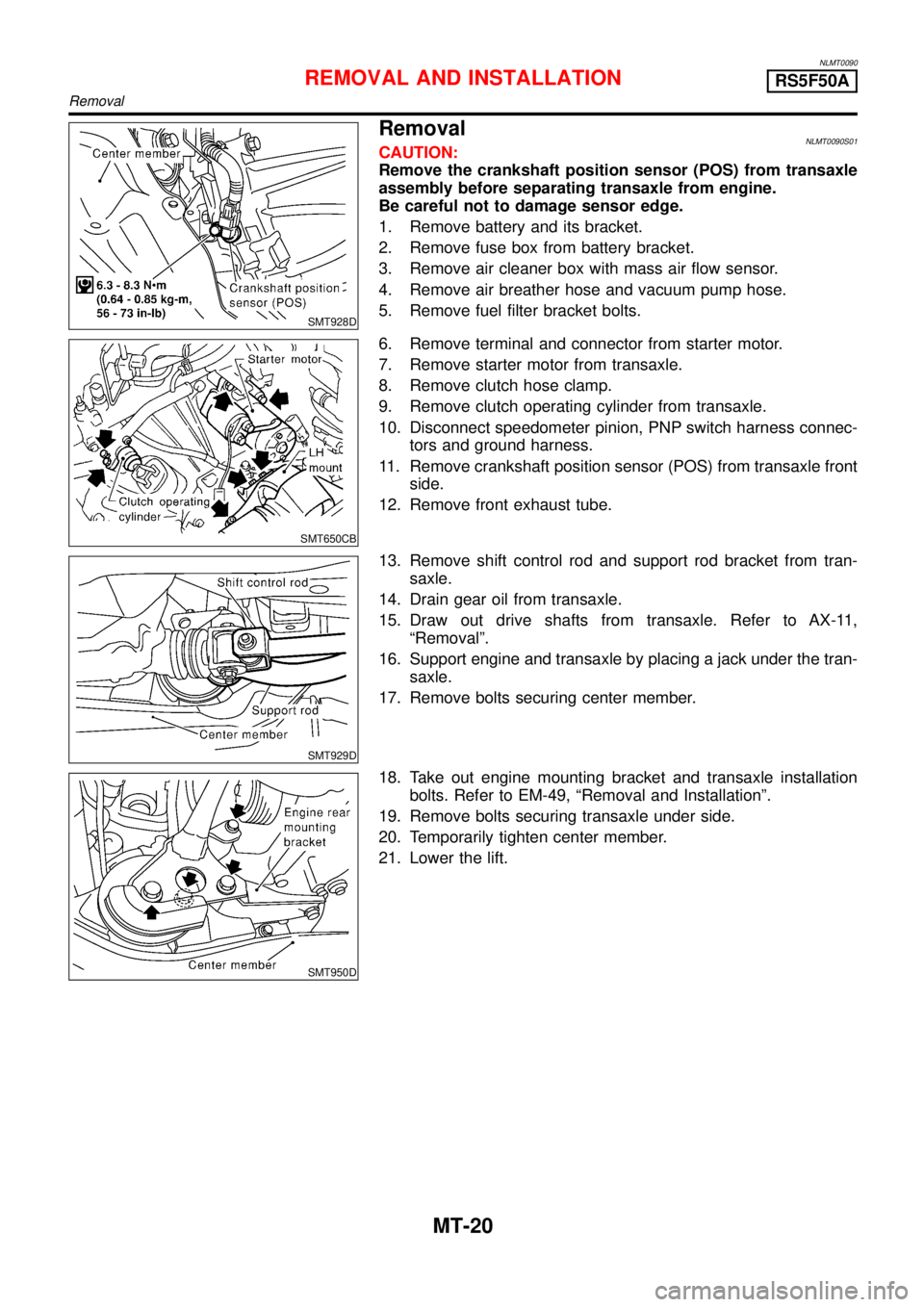
NLMT0090
SMT928D
RemovalNLMT0090S01CAUTION:
Remove the crankshaft position sensor (POS) from transaxle
assembly before separating transaxle from engine.
Be careful not to damage sensor edge.
1. Remove battery and its bracket.
2. Remove fuse box from battery bracket.
3. Remove air cleaner box with mass air flow sensor.
4. Remove air breather hose and vacuum pump hose.
5. Remove fuel filter bracket bolts.
SMT650CB
6. Remove terminal and connector from starter motor.
7. Remove starter motor from transaxle.
8. Remove clutch hose clamp.
9. Remove clutch operating cylinder from transaxle.
10. Disconnect speedometer pinion, PNP switch harness connec-
tors and ground harness.
11. Remove crankshaft position sensor (POS) from transaxle front
side.
12. Remove front exhaust tube.
SMT929D
13. Remove shift control rod and support rod bracket from tran-
saxle.
14. Drain gear oil from transaxle.
15. Draw out drive shafts from transaxle. Refer to AX-11,
“Removal”.
16. Support engine and transaxle by placing a jack under the tran-
saxle.
17. Remove bolts securing center member.
SMT950D
18. Take out engine mounting bracket and transaxle installation
bolts. Refer to EM-49,“Removal and Installation”.
19. Remove bolts securing transaxle under side.
20. Temporarily tighten center member.
21. Lower the lift.
REMOVAL AND INSTALLATIONRS5F50A
Removal
MT-20