2001 NISSAN ALMERA TINO battery
[x] Cancel search: batteryPage 1076 of 3051

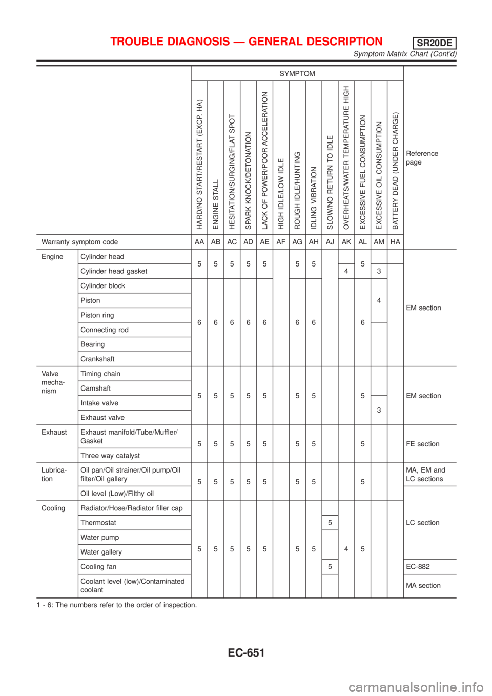
SYMPTOM
Reference
page
HARD/NO START/RESTART (EXCP. HA)
ENGINE STALL
HESITATION/SURGING/FLAT SPOT
SPARK KNOCK/DETONATION
LACK OF POWER/POOR ACCELERATION
HIGH IDLE/LOW IDLE
ROUGH IDLE/HUNTING
IDLING VIBRATION
SLOW/NO RETURN TO IDLE
OVERHEATS/WATER TEMPERATURE HIGH
EXCESSIVE FUEL CONSUMPTION
EXCESSIVE OIL CONSUMPTION
BATTERY DEAD (UNDER CHARGE)
Warranty symptom code AA AB AC AD AE AF AG AH AJ AK AL AM HA
Engine Cylinder head
55555 55 5
EM section Cylinder head gasket 4 3
Cylinder block
66666 66 64 Piston
Piston ring
Connecting rod
Bearing
Crankshaft
Valve
mecha-
nismTiming chain
55555 55 5 EMsection Camshaft
Intake valve
3
Exhaust valve
Exhaust Exhaust manifold/Tube/Muffler/
Gasket
55555 55 5 FEsection
Three way catalyst
Lubrica-
tionOil pan/Oil strainer/Oil pump/Oil
filter/Oil gallery
55555 55 5MA, EM and
LC sections
Oil level (Low)/Filthy oil
LC section Cooling Radiator/Hose/Radiator filler cap
55555 55 45 Thermostat 5
Water pump
Water gallery
Cooling fan 5 EC-882
Coolant level (low)/Contaminated
coolantMA section
1 - 6: The numbers refer to the order of inspection.
TROUBLE DIAGNOSIS Ð GENERAL DESCRIPTIONSR20DE
Symptom Matrix Chart (Cont'd)
EC-651
Page 1077 of 3051

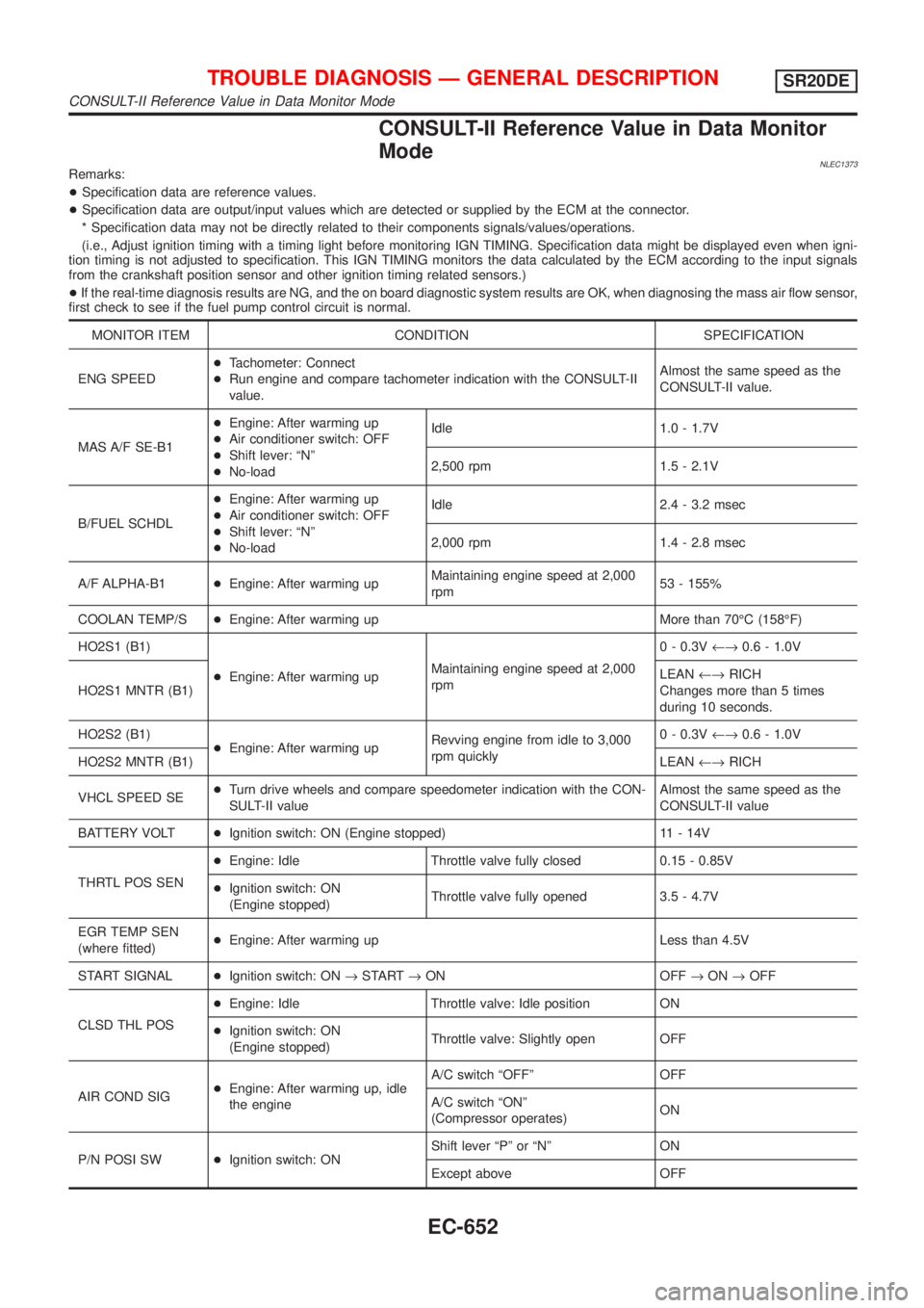
CONSULT-II Reference Value in Data Monitor
Mode
NLEC1373Remarks:
+Specification data are reference values.
+Specification data are output/input values which are detected or supplied by the ECM at the connector.
* Specification data may not be directly related to their components signals/values/operations.
(i.e., Adjust ignition timing with a timing light before monitoring IGN TIMING. Specification data might be displayed even when igni-
tion timing is not adjusted to specification. This IGN TIMING monitors the data calculated by the ECM according to the input signals
from the crankshaft position sensor and other ignition timing related sensors.)
+If the real-time diagnosis results are NG, and the on board diagnostic system results are OK, when diagnosing the mass air flow sensor,
first check to see if the fuel pump control circuit is normal.
MONITOR ITEM CONDITION SPECIFICATION
ENG SPEED+Tachometer: Connect
+Run engine and compare tachometer indication with the CONSULT-II
value.Almost the same speed as the
CONSULT-II value.
MAS A/F SE-B1+Engine: After warming up
+Air conditioner switch: OFF
+Shift lever: ªNº
+No-loadIdle 1.0 - 1.7V
2,500 rpm 1.5 - 2.1V
B/FUEL SCHDL+Engine: After warming up
+Air conditioner switch: OFF
+Shift lever: ªNº
+No-loadIdle 2.4 - 3.2 msec
2,000 rpm 1.4 - 2.8 msec
A/F ALPHA-B1+Engine: After warming upMaintaining engine speed at 2,000
rpm53 - 155%
COOLAN TEMP/S+Engine: After warming up More than 70ÉC (158ÉF)
HO2S1 (B1)
+Engine: After warming upMaintaining engine speed at 2,000
rpm0 - 0.3V¨0.6 - 1.0V
HO2S1 MNTR (B1)LEAN¨RICH
Changes more than 5 times
during 10 seconds.
HO2S2 (B1)
+Engine: After warming upRevving engine from idle to 3,000
rpm quickly0 - 0.3V¨0.6 - 1.0V
HO2S2 MNTR (B1)LEAN¨RICH
VHCL SPEED SE+Turn drive wheels and compare speedometer indication with the CON-
SULT-II valueAlmost the same speed as the
CONSULT-II value
BATTERY VOLT+Ignition switch: ON (Engine stopped) 11 - 14V
THRTL POS SEN+Engine: Idle Throttle valve fully closed 0.15 - 0.85V
+Ignition switch: ON
(Engine stopped)Throttle valve fully opened 3.5 - 4.7V
EGR TEMP SEN
(where fitted)+Engine: After warming up Less than 4.5V
START SIGNAL+Ignition switch: ON®START®ON OFF®ON®OFF
CLSD THL POS+Engine: Idle Throttle valve: Idle position ON
+Ignition switch: ON
(Engine stopped)Throttle valve: Slightly open OFF
AIR COND SIG+Engine: After warming up, idle
the engineA/C switch ªOFFº OFF
A/C switch ªONº
(Compressor operates)ON
P/N POSI SW+Ignition switch: ONShift lever ªPº or ªNº ON
Except above OFF
TROUBLE DIAGNOSIS Ð GENERAL DESCRIPTIONSR20DE
CONSULT-II Reference Value in Data Monitor Mode
EC-652
Page 1084 of 3051

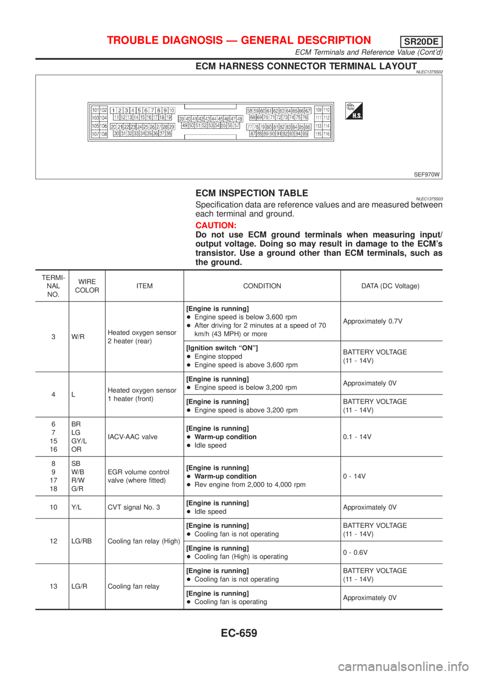
ECM HARNESS CONNECTOR TERMINAL LAYOUTNLEC1375S02
SEF970W
ECM INSPECTION TABLENLEC1375S03Specification data are reference values and are measured between
each terminal and ground.
CAUTION:
Do not use ECM ground terminals when measuring input/
output voltage. Doing so may result in damage to the ECM's
transistor. Use a ground other than ECM terminals, such as
the ground.
TERMI-
NAL
NO.WIRE
COLORITEM CONDITION DATA (DC Voltage)
3 W/RHeated oxygen sensor
2 heater (rear)[Engine is running]
+Engine speed is below 3,600 rpm
+After driving for 2 minutes at a speed of 70
km/h (43 MPH) or moreApproximately 0.7V
[Ignition switch ªONº]
+Engine stopped
+Engine speed is above 3,600 rpmBATTERY VOLTAGE
(11 - 14V)
4LHeated oxygen sensor
1 heater (front)[Engine is running]
+Engine speed is below 3,200 rpmApproximately 0V
[Engine is running]
+Engine speed is above 3,200 rpmBATTERY VOLTAGE
(11 - 14V)
6
7
15
16BR
LG
GY/L
ORIACV-AAC valve[Engine is running]
+Warm-up condition
+Idle speed0.1 - 14V
8
9
17
18SB
W/B
R/W
G/REGR volume control
valve (where fitted)[Engine is running]
+Warm-up condition
+Rev engine from 2,000 to 4,000 rpm0 - 14V
10 Y/L CVT signal No. 3[Engine is running]
+Idle speedApproximately 0V
12 LG/RB Cooling fan relay (High)[Engine is running]
+Cooling fan is not operatingBATTERY VOLTAGE
(11 - 14V)
[Engine is running]
+Cooling fan (High) is operating0 - 0.6V
13 LG/R Cooling fan relay[Engine is running]
+Cooling fan is not operatingBATTERY VOLTAGE
(11 - 14V)
[Engine is running]
+Cooling fan is operatingApproximately 0V
TROUBLE DIAGNOSIS Ð GENERAL DESCRIPTIONSR20DE
ECM Terminals and Reference Value (Cont'd)
EC-659
Page 1085 of 3051
![NISSAN ALMERA TINO 2001 Service Repair Manual TERMI-
NAL
NO.WIRE
COLORITEM CONDITION DATA (DC Voltage)
14 PEVAP canister purge
volume control valve
(ON/OFF duty)[Engine is running]
+Warm-up condition
+Idle speedBATTERY VOLTAGE
(11 - 14V)
[Engine NISSAN ALMERA TINO 2001 Service Repair Manual TERMI-
NAL
NO.WIRE
COLORITEM CONDITION DATA (DC Voltage)
14 PEVAP canister purge
volume control valve
(ON/OFF duty)[Engine is running]
+Warm-up condition
+Idle speedBATTERY VOLTAGE
(11 - 14V)
[Engine](/manual-img/5/57352/w960_57352-1084.png)
TERMI-
NAL
NO.WIRE
COLORITEM CONDITION DATA (DC Voltage)
14 PEVAP canister purge
volume control valve
(ON/OFF duty)[Engine is running]
+Warm-up condition
+Idle speedBATTERY VOLTAGE
(11 - 14V)
[Engine is running]
+Warm-up condition
+Engine speed is about 2,000 rpm5 - 12V
SEF975W
19 BR/W CVT signal No. 5[Engine is running]
+Idle speedApproximately 7.5V
21 B/P Fuel pump relay[Ignition switch ªONº]
+For 1 second after turning ignition switch ªONº
[Engine is running]0-1V
[Ignition switch ªONº]
+More than 1 second after turning ignition
switch ªONºBATTERY VOLTAGE
(11 - 14V)
22 OR/L Malfunction indicator[Ignition switch ªONº]0-1V
[Engine is running]
+Idle speedBATTERY VOLTAGE
(11 - 14V)
23 L Air conditioner relay[Engine is running]
+Both A/C switch and blower switch are ªONºApproximately 0V
[Engine is running]
+A/C switch is ªOFFºBATTERY VOLTAGE
(11 - 14V)
31 W/GECM relay (Self shut-
off)[Ignition switch ªOFFº]
+For a few seconds after turning ignition switch
ªOFFº0-1V
[Ignition switch ªOFFº]
+A few seconds passed after turning ignition
switch ªOFFºBATTERY VOLTAGE
(11 - 14V)
32 L/OR Tachometer[Engine is running]
+Warm-up condition
+Idle speedApproximately 10.5V
SEF973W
[Engine is running]
+Engine speed is 2,000 rpmApproximately 10.5V
SEF974W
TROUBLE DIAGNOSIS Ð GENERAL DESCRIPTIONSR20DE
ECM Terminals and Reference Value (Cont'd)
EC-660
Page 1086 of 3051
![NISSAN ALMERA TINO 2001 Service Repair Manual TERMI-
NAL
NO.WIRE
COLORITEM CONDITION DATA (DC Voltage)
35 W/B Ignition signal[Engine is running]
+Warm-up condition
+Idle speedApproximately 0.3V
SEF996V
[Engine is running]
+Engine speed is 2,000 r NISSAN ALMERA TINO 2001 Service Repair Manual TERMI-
NAL
NO.WIRE
COLORITEM CONDITION DATA (DC Voltage)
35 W/B Ignition signal[Engine is running]
+Warm-up condition
+Idle speedApproximately 0.3V
SEF996V
[Engine is running]
+Engine speed is 2,000 r](/manual-img/5/57352/w960_57352-1085.png)
TERMI-
NAL
NO.WIRE
COLORITEM CONDITION DATA (DC Voltage)
35 W/B Ignition signal[Engine is running]
+Warm-up condition
+Idle speedApproximately 0.3V
SEF996V
[Engine is running]
+Engine speed is 2,000 rpmApproximately 0.5V
SEF997V
36 G Ignition check[Engine is running]
+Warm-up condition
+Idle speedApproximately 13VSEF998V
[Engine is running]
+Engine speed is 2,000 rpmApproximately 13V
SEF999V
40 Y/PUThrottle position switch
(Closed position)[Engine is running]
+Accelerator pedal releasedBATTERY VOLTAGE
(11 - 14V)
[Ignition switch ªONº]
+Accelerator pedal depressedApproximately 0V
41 B/Y Start signal[Ignition switch ªONº]Approximately 0V
[Ignition switch ªSTARTº]9 - 12V
42 G/OR PNP switch[Ignition switch ªONº]
+Gear position is ªPº or ªNºApproximately 0V
[Ignition switch ªONº]
+Except the above gear positionBATTERY VOLTAGE
(11 - 14V)
43 B/R Ignition switch[Ignition switch ªOFFº]0V
[Ignition switch ªONº]BATTERY VOLTAGE
(11 - 14V)
TROUBLE DIAGNOSIS Ð GENERAL DESCRIPTIONSR20DE
ECM Terminals and Reference Value (Cont'd)
EC-661
Page 1087 of 3051
![NISSAN ALMERA TINO 2001 Service Repair Manual TERMI-
NAL
NO.WIRE
COLORITEM CONDITION DATA (DC Voltage)
44 L/R Air conditioner switch[Engine is running]
+Both air conditioner switch and blower switch
are ªONº (Compressor operates)Approximately 0 NISSAN ALMERA TINO 2001 Service Repair Manual TERMI-
NAL
NO.WIRE
COLORITEM CONDITION DATA (DC Voltage)
44 L/R Air conditioner switch[Engine is running]
+Both air conditioner switch and blower switch
are ªONº (Compressor operates)Approximately 0](/manual-img/5/57352/w960_57352-1086.png)
TERMI-
NAL
NO.WIRE
COLORITEM CONDITION DATA (DC Voltage)
44 L/R Air conditioner switch[Engine is running]
+Both air conditioner switch and blower switch
are ªONº (Compressor operates)Approximately 0V
[Engine is running]
+Air conditioner switch is ªOFFºApproximately 5V
46 PU/WPower steering oil pres-
sure switch[Engine is running]
+Steering wheel is fully turnedApproximately 0V
[Engine is running]
+Steering wheel is not turnedApproximately 5V
48 B ECM ground[Engine is running]
+Idle speedEngine ground
50 L/BElectrical load signal
(Headlamp and
Rear defogger)[Engine is running]
+Headlamp switch or rear defogger switch is
ªONºBATTERY VOLTAGE
(11 - 14V)
[Engine is running]
+Headlamp switch and rear defogger switch are
ªOFFºApproximately 0V
51 LG/B Blower fan SW[Ignition switch ªONº]
+Blower fan switch is ªONºApproximately 0V
[Ignition switch ªONº]
+Blower fan switch is ªOFFºApproximately 5V
54 Y/R CVT signal No. 1[Engine is running]
+Idle speedApproximately 0 - 3.5V
55 Y/G CVT signal No. 2[Engine is running]
+Idle speedApproximately 0 - 3.5V
56 G/Y CVT signal No. 4[Engine is running]
+Idle speed
+ªRº positionApproximately 0 - 3.5V
57 B ECM ground[Engine is running]
+Idle speedEngine ground
58 B Sensors' ground[Engine is running]
+Warm-up condition
+Idle speedApproximately 0V
61 G Mass air flow sensor[Engine is running]
+Warm-up condition
+Idle speed1.3 - 1.7V
[Engine is running]
+Warm-up condition
+Engine speed is 2,500 rpm1.8 - 2.4V
62 WHeated oxygen sensor
1 (front)[Engine is running]
+Warm-up condition
+Engine speed is 2,000 rpm0 - Approximately 1.0V
SEF008W
TROUBLE DIAGNOSIS Ð GENERAL DESCRIPTIONSR20DE
ECM Terminals and Reference Value (Cont'd)
EC-662
Page 1088 of 3051
![NISSAN ALMERA TINO 2001 Service Repair Manual TERMI-
NAL
NO.WIRE
COLORITEM CONDITION DATA (DC Voltage)
63 LHeated oxygen sensor
2 (rear)[Engine is running]
+After warming up to normal operating tempera-
ture and engine speed is 3,000 rpm0 - Appro NISSAN ALMERA TINO 2001 Service Repair Manual TERMI-
NAL
NO.WIRE
COLORITEM CONDITION DATA (DC Voltage)
63 LHeated oxygen sensor
2 (rear)[Engine is running]
+After warming up to normal operating tempera-
ture and engine speed is 3,000 rpm0 - Appro](/manual-img/5/57352/w960_57352-1087.png)
TERMI-
NAL
NO.WIRE
COLORITEM CONDITION DATA (DC Voltage)
63 LHeated oxygen sensor
2 (rear)[Engine is running]
+After warming up to normal operating tempera-
ture and engine speed is 3,000 rpm0 - Approximately 1.0V
64 W/RIntake air temperature
sensor[Engine is running]Approximately 0 - 4.8V
Output voltage varies with
intake air temperature
65 WCrankshaft position
sensor (OBD)[Engine is running]
+Warm-up condition
+Idle speedApproximately 1.3V (AC
range)
SEF814Z
[Engine is running]
+Engine speed is 2,000 rpmApproximately 2.0V (AC
range)
SEF815Z
66
75L
LCamshaft position sen-
sor (Reference signal)[Engine is running]
+Warm-up condition
+Idle speed0.1 - 0.4VSEF006W
[Engine is running]
+Engine speed is 2,000 rpm0.1 - 0.4V
SEF007W
67 W/LPower supply for ECM
(Back-up)[Ignition switch ªOFFº]BATTERY VOLTAGE
(11 - 14V)
70 BR/YEngine coolant tem-
perature sensor[Engine is running]Approximately 0 - 4.8V
Output voltage varies with
engine coolant temperature
71 GYThrottle position sensor
signal output[Engine is running]
+Warm-up condition
+Accelerator pedal fully released0.15 - 0.85V
[Ignition switch ªONº]
+Accelerator pedal fully depressed3.5 - 4.7V
TROUBLE DIAGNOSIS Ð GENERAL DESCRIPTIONSR20DE
ECM Terminals and Reference Value (Cont'd)
EC-663
Page 1090 of 3051
![NISSAN ALMERA TINO 2001 Service Repair Manual TERMI-
NAL
NO.WIRE
COLORITEM CONDITION DATA (DC Voltage)
101
103
105
107R/B
Y/B
G/B
L/BInjector No. 1
Injector No. 2
Injector No. 3
Injector No. 4[Engine is running]
+Warm-up condition
+Idle speedBATT NISSAN ALMERA TINO 2001 Service Repair Manual TERMI-
NAL
NO.WIRE
COLORITEM CONDITION DATA (DC Voltage)
101
103
105
107R/B
Y/B
G/B
L/BInjector No. 1
Injector No. 2
Injector No. 3
Injector No. 4[Engine is running]
+Warm-up condition
+Idle speedBATT](/manual-img/5/57352/w960_57352-1089.png)
TERMI-
NAL
NO.WIRE
COLORITEM CONDITION DATA (DC Voltage)
101
103
105
107R/B
Y/B
G/B
L/BInjector No. 1
Injector No. 2
Injector No. 3
Injector No. 4[Engine is running]
+Warm-up condition
+Idle speedBATTERY VOLTAGE
(11 - 14V)
SEF011W
[Engine is running]
+Warm-up condition
+Engine speed is 2,000 rpmBATTERY VOLTAGE
(11 - 14V)
SEF012W
106
108B/Y
B/YECM ground[Engine is running]
+Idle speedEngine ground
11 0
11 2W
WPower supply for ECM[Ignition switch ªONº]BATTERY VOLTAGE
(11 - 14V)
111 R Sensors' power supply[Ignition switch ªONº]Approximately 5V
114 G/W Data link connector[Engine is running]
+Idle speed (CONSULT-II or GST is discon-
nected)0V
115 LG Data link connector[Engine is running]
+Idle speed (CONSULT-II or GST is discon-
nected)0 - 10V
TROUBLE DIAGNOSIS Ð GENERAL DESCRIPTIONSR20DE
ECM Terminals and Reference Value (Cont'd)
EC-665