Page 978 of 2493

6 CHECK GLOW INDICATOR LAMP POWER SUPPLY CIRCUIT
1. Turn ignition switch ªOFFº.
2. Disconnect combination meter harness connector M32 or M152 or M171.
3. Turn ignition switch ªONº.
4. Check voltage between combination meter terminal 40 or 17 or 1 and ground with CONSULT-II or tester.
YEC060A
OK or NG
OK©GO TO 8.
NG©GO TO 7.
7 DETECT MALFUNCTIONING PART
Check the following.
1. Fuse block (J/B) connector M1
2. 10A fuse
3. Harness for open or short between combination meter and fuse
©Repair open circuit or short to ground or short to power in harness or connectors.
8 CHECK GLOW INDICATOR LAMP OUTPUT SIGNAL CIRCUIT FOR OPEN AND SHORT
1. Turn ignition switch ªOFFº.
2. Disconnect ECM harness connector.
3. Disconnect combination meter harness connector M171.
4. Check harness continuity between ECM terminal 508 and combination meter terminal 17. Refer to Wiring Diagram.
Continuity should exist.
5. Also check harness for short to ground and short to power.
OK or NG
OK©GO TO 10.
NG©GO TO 9.
9 DETECT MALFUNCTIONING PART
Check the following.
1. Harness connectors M63, F102
2. Harness for open or short between combination meter and ECM
©Repair open circuit or short to ground or short to power in harness or connectors.
10 CHECK COMBINATION METER
Check combination meter and glow indicator lamp. Refer to EL-89, ªMeter and Gaugesº.
OK or NG
OK©GO TO 18.
NG©Repair or replace combination meter or glow indicator lamp.
GLOW CONTROL SYSTEMYD
Diagnostic Procedure (Cont'd)
EC-682
Page 986 of 2493

3 CHECK EGR VOLUME CONTROL VALVE POWER SUPPLY CIRCUIT-II
1. Turn ignition switch ªOFFº.
2. Disconnect ECM relay. (For ECM relay location, refer to ªEngine Control Component Parts Locationº.)
3. Check harness continuity between ECM relay terminal 5 and EGR volume control valve terminals 2 and 5. Refer to
Wiring Diagram.
Continuity should exist.
OK or NG
OK©GO TO 4.
NG©Repair open circuit or short to ground or short to power in harness or connectors.
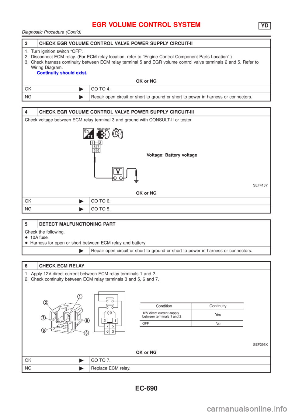
4 CHECK EGR VOLUME CONTROL VALVE POWER SUPPLY CIRCUIT-III
Check voltage between ECM relay terminal 3 and ground with CONSULT-II or tester.
SEF413Y
OK or NG
OK©GO TO 6.
NG©GO TO 5.
5 DETECT MALFUNCTIONING PART
Check the following.
+10A fuse
+Harness for open or short between ECM relay and battery
©Repair open circuit or short to ground or short to power in harness or connectors.
6 CHECK ECM RELAY
1. Apply 12V direct current between ECM relay terminals 1 and 2.
2. Check continuity between ECM relay terminals 3 and 5, 6 and 7.
SEF296X
OK or NG
OK©GO TO 7.
NG©Replace ECM relay.
EGR VOLUME CONTROL SYSTEMYD
Diagnostic Procedure (Cont'd)
EC-690
Page 990 of 2493

Diagnostic ProcedureNJEC0770
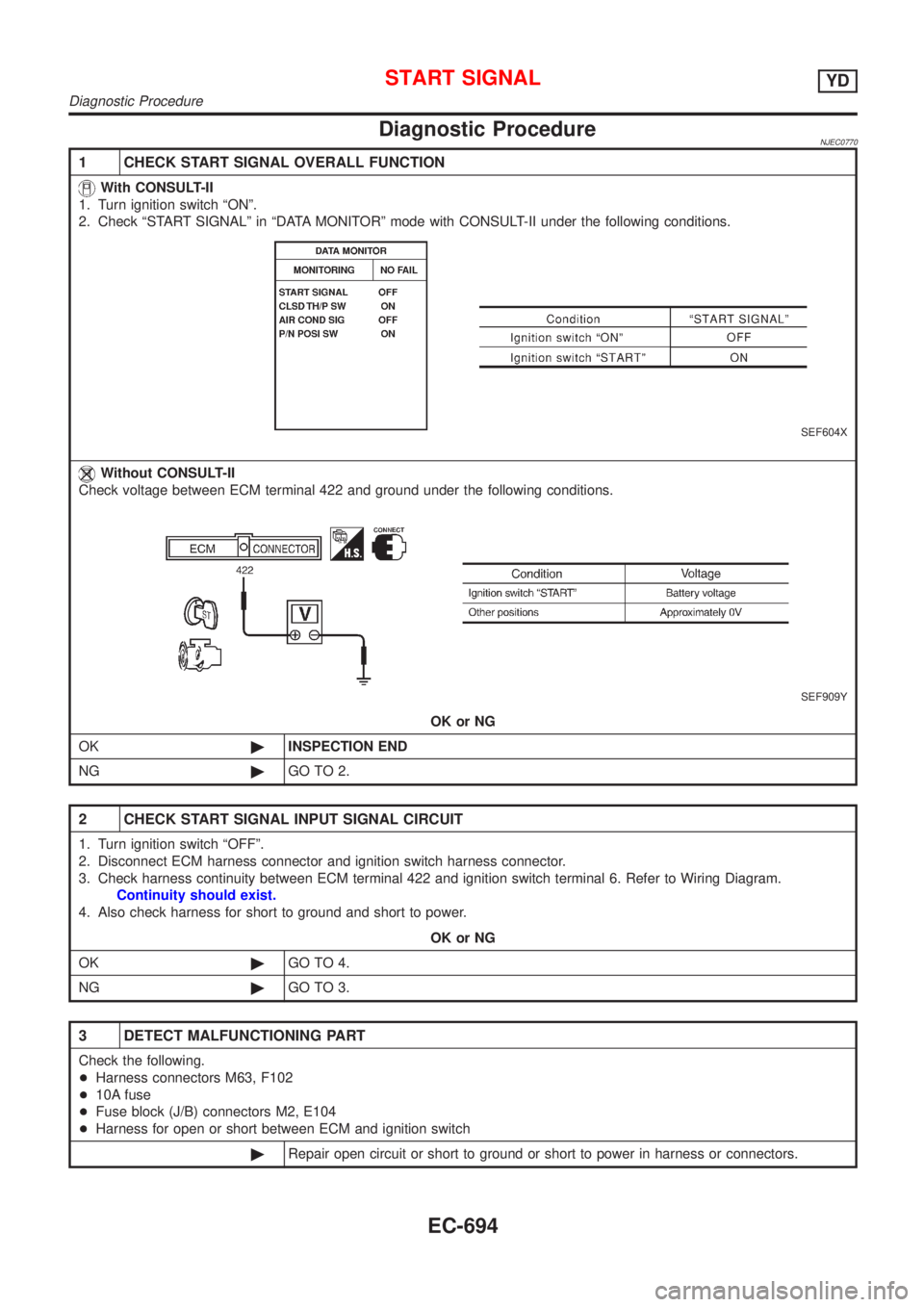
1 CHECK START SIGNAL OVERALL FUNCTION
With CONSULT-II
1. Turn ignition switch ªONº.
2. Check ªSTART SIGNALº in ªDATA MONITORº mode with CONSULT-II under the following conditions.
SEF604X
Without CONSULT-II
Check voltage between ECM terminal 422 and ground under the following conditions.
SEF909Y
OK or NG
OK©INSPECTION END
NG©GO TO 2.
2 CHECK START SIGNAL INPUT SIGNAL CIRCUIT
1. Turn ignition switch ªOFFº.
2. Disconnect ECM harness connector and ignition switch harness connector.
3. Check harness continuity between ECM terminal 422 and ignition switch terminal 6. Refer to Wiring Diagram.
Continuity should exist.
4. Also check harness for short to ground and short to power.
OK or NG
OK©GO TO 4.
NG©GO TO 3.
3 DETECT MALFUNCTIONING PART
Check the following.
+Harness connectors M63, F102
+10A fuse
+Fuse block (J/B) connectors M2, E104
+Harness for open or short between ECM and ignition switch
©Repair open circuit or short to ground or short to power in harness or connectors.
START SIGNALYD
Diagnostic Procedure
EC-694
Page 1309 of 2493
2 CHECK TCM POWER SOURCE STEP 2
1. Turn ignition switch to OFF position.
2. Check voltage between TCM terminal 28 and ground.
NAT350
OK or NG
OK©GO TO 4.
NG©GO TO 3.
3 DETECT MALFUNCTIONING ITEM
Check the following items:
+Harness for short or open between ignition switch and TCM terminals 10, 19 and 28 (Main harness)
+Fuse
+Ignition switch
Refer to EL-10, ªPOWER SUPPLY ROUTINGº.
OK or NG
OK©GO TO 4.
NG©Repair or replace damaged parts.
4 CHECK TCM GROUND CIRCUIT
1. Turn ignition switch to OFF position.
2. Disconnect TCM harness connector.
3. Check continuity between TCM terminals 25, 48 and ground. Refer to wiring diagram Ð AT Ð MAIN.
Continuity should exist.
If OK, check harness for short to ground and short to power.
OK or NG
OK©INSPECTION END
NG©Repair open circuit or short to ground or short to power in harness or connectors.
TROUBLE DIAGNOSIS FOR POWER SUPPLY
Diagnostic Procedure (Cont'd)
AT-123
Page 1474 of 2493
SAT466J
1. O/D OFF Indicator Lamp Does Not Come On=NJAT0331SYMPTOM:
O/D OFF indicator lamp does not come on for about 2 seconds
when turning ignition switch to ªONº.
1 CHECK TCM POWER SOURCE
1. Turn ignition switch to ªONº position.
(Do not start engine.)
2. Check voltage between TCM terminals 10, 19, 28 and ground.
Voltage: Battery voltage
SAT467J
3. Turn ignition switch to ªOFFº position.
4. Check voltage between TCM terminal 28 and ground.
Voltage: Battery voltage
OK or NG
OK©GO TO 2.
NG©Check the following items:
+Harness for short or open between ignition switch and TCM terminals 10, 19 and 28
(Main harness).
+Refer to ªWiring Diagram Ð AT Ð MAINº, AT-121.
+Ignition switch and fuse Refer to EL-10, ªPOWER SUPPLY ROUTINGº.
TROUBLE DIAGNOSES FOR SYMPTOMS
1. O/D OFF Indicator Lamp Does Not Come On
AT-288
Page 1475 of 2493

2 CHECK TCM GROUND CIRCUIT
1. Turn ignition switch to ªOFFº position.
2. Disconnect TCM harness connector.
3. Check continuity between TCM terminals 25, 48 and ground.
SAT468J
Continuity should exist.
If OK, check harness for short to ground and short to power.
OK or NG
OK©GO TO 3.
NG©Repair open circuit or short to ground or short to power in harness or connectors. Refer
to ªWiring Diagram Ð AT Ð MAINº, AT-121.
3 CHECK LAMP CIRCUIT
1. Turn ignition switch to ªOFFº position.
2. Check resistance between TCM terminals 13 and 10.
Resistance: 50 - 100W
SAT469JB
3. Reinstall any part removed.
OK or NG
OK©GO TO 4.
NG©Check the following items:
+O/D OFF indicator lamp.
Refer to EL-89, ªMETERS AND GAUGESº.
+Harness and fuse for short or open between ignition switch and O/D OFF indicator
lamp (Main harness)
Refer to EL-10, ªPOWER SUPPLY ROUTINGº.
+Harness for short or open between O/D OFF indicator lamp and TCM.
TROUBLE DIAGNOSES FOR SYMPTOMS
1. O/D OFF Indicator Lamp Does Not Come On (Cont'd)
AT-289
Page 2015 of 2493
RHA623H
COMPONENT DESCRIPTIONNJHA0209Intake Door MotorNJHA0209S01The intake door motor is attached to the intake unit. It rotates so
that air is drawn from inlets set by the heater control panel. Motor
rotation is conveyed to a lever which activates the intake door.
DIAGNOSTIC PROCEDURE FOR INTAKE DOOR
MOTOR CIRCUIT
NJHA0210
1 CHECK POWER SUPPLY FOR HEATER CONTROL PANEL
Do approx. 12 volts exist between heater control panel harness terminal No. 1 and body ground?
NHA495
YesorNo
Ye s©GO TO 2.
No©Check 10A (No. 15) fuse at fuse block. Refer to Sedan: EL-23 (QG), EL-0 (YD), Hatch-
back: EL-12, ªWiring Diagram Ð POWER к.
2 CHECK RECIRCULATION (REC) SWITCH
Refer to HA-45.
OK or NG
OK©GO TO 3.
NG©Replace recirculation (REC) switch.
TROUBLE DIAGNOSES
Intake Door (Cont'd)
HA-43
Page 2027 of 2493
BLOWER MOTOR CIRCUIT=NJHA0147SYMPTOM:
+Blower motor does not rotate.
Symptom
table No.INCIDENT
1 Fan fails to rotate.
2 Fan does not rotate at 1-speed.
3 Fan does not rotate at 2-speed.
4 Fan does not rotate at 3-speed.
5 Fan does not rotate at 4-speed.
1 DIAGNOSTIC PROCEDURE
Check if blower motor rotates properly at each fan speed.
Conduct checks as per symptom table at above.
1©GO TO 2.
2, 3, 4©GO TO 8.
5©GO TO 10.
2 CHECK POWER SUPPLY FOR BLOWER MOTOR
1. Disconnect blower motor harness connector.
2. Do approx. 12 volts exist between blower motor harness terminal No. 1 and body ground?
RHA343FD
YesorNo
Ye s©GO TO 3.
No©Check 15A (Nos. 14 and 16) fuses at fuse block. Refer to Sedan: EL-23 (QG), EL-0
(YD), Hatchback: EL-12, ªWiring Diagram Ð POWER к.
TROUBLE DIAGNOSES
Blower Motor (Cont'd)
HA-55