2001 NISSAN ALMERA N16 service
[x] Cancel search: servicePage 823 of 2493
SEF378Y
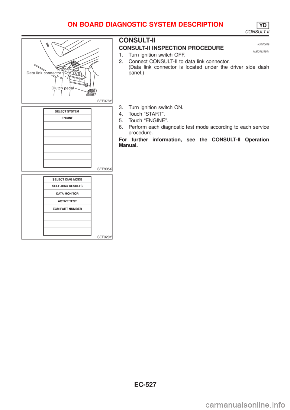
CONSULT-IINJEC0629CONSULT-II INSPECTION PROCEDURENJEC0629S011. Turn ignition switch OFF.
2. Connect CONSULT-II to data link connector.
(Data link connector is located under the driver side dash
panel.)
SEF995X
SEF320Y
3. Turn ignition switch ON.
4. Touch ªSTARTº.
5. Touch ªENGINEº.
6. Perform each diagnostic test mode according to each service
procedure.
For further information, see the CONSULT-II Operation
Manual.
ON BOARD DIAGNOSTIC SYSTEM DESCRIPTIONYD
CONSULT-II
EC-527
Page 831 of 2493
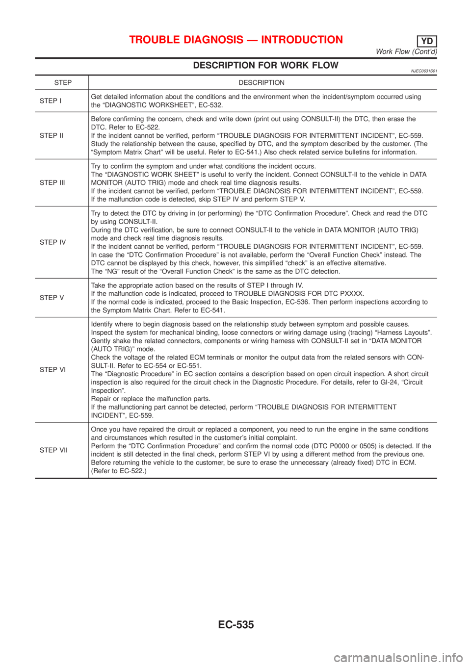
DESCRIPTION FOR WORK FLOWNJEC0631S01
STEP DESCRIPTION
STEP IGet detailed information about the conditions and the environment when the incident/symptom occurred using
the ªDIAGNOSTIC WORKSHEETº, EC-532.
STEP IIBefore confirming the concern, check and write down (print out using CONSULT-II) the DTC, then erase the
DTC. Refer to EC-522.
If the incident cannot be verified, perform ªTROUBLE DIAGNOSIS FOR INTERMITTENT INCIDENTº, EC-559.
Study the relationship between the cause, specified by DTC, and the symptom described by the customer. (The
ªSymptom Matrix Chartº will be useful. Refer to EC-541.) Also check related service bulletins for information.
STEP IIITry to confirm the symptom and under what conditions the incident occurs.
The ªDIAGNOSTIC WORK SHEETº is useful to verify the incident. Connect CONSULT-II to the vehicle in DATA
MONITOR (AUTO TRIG) mode and check real time diagnosis results.
If the incident cannot be verified, perform ªTROUBLE DIAGNOSIS FOR INTERMITTENT INCIDENTº, EC-559.
If the malfunction code is detected, skip STEP IV and perform STEP V.
STEP IVTry to detect the DTC by driving in (or performing) the ªDTC Confirmation Procedureº. Check and read the DTC
by using CONSULT-II.
During the DTC verification, be sure to connect CONSULT-II to the vehicle in DATA MONITOR (AUTO TRIG)
mode and check real time diagnosis results.
If the incident cannot be verified, perform ªTROUBLE DIAGNOSIS FOR INTERMITTENT INCIDENTº, EC-559.
In case the ªDTC Confirmation Procedureº is not available, perform the ªOverall Function Checkº instead. The
DTC cannot be displayed by this check, however, this simplified ªcheckº is an effective alternative.
The ªNGº result of the ªOverall Function Checkº is the same as the DTC detection.
STEP VTake the appropriate action based on the results of STEP I through IV.
If the malfunction code is indicated, proceed to TROUBLE DIAGNOSIS FOR DTC PXXXX.
If the normal code is indicated, proceed to the Basic Inspection, EC-536. Then perform inspections according to
the Symptom Matrix Chart. Refer to EC-541.
STEP VIIdentify where to begin diagnosis based on the relationship study between symptom and possible causes.
Inspect the system for mechanical binding, loose connectors or wiring damage using (tracing) ªHarness Layoutsº.
Gently shake the related connectors, components or wiring harness with CONSULT-II set in ªDATA MONITOR
(AUTO TRIG)º mode.
Check the voltage of the related ECM terminals or monitor the output data from the related sensors with CON-
SULT-II. Refer to EC-554 or EC-551.
The ªDiagnostic Procedureº in EC section contains a description based on open circuit inspection. A short circuit
inspection is also required for the circuit check in the Diagnostic Procedure. For details, refer to GI-24, ªCircuit
Inspectionº.
Repair or replace the malfunction parts.
If the malfunctioning part cannot be detected, perform ªTROUBLE DIAGNOSIS FOR INTERMITTENT
INCIDENTº, EC-559.
STEP VIIOnce you have repaired the circuit or replaced a component, you need to run the engine in the same conditions
and circumstances which resulted in the customer's initial complaint.
Perform the ªDTC Confirmation Procedureº and confirm the normal code (DTC P0000 or 0505) is detected. If the
incident is still detected in the final check, perform STEP VI by using a different method from the previous one.
Before returning the vehicle to the customer, be sure to erase the unnecessary (already fixed) DTC in ECM.
(Refer to EC-522.)
TROUBLE DIAGNOSIS Ð INTRODUCTIONYD
Work Flow (Cont'd)
EC-535
Page 832 of 2493
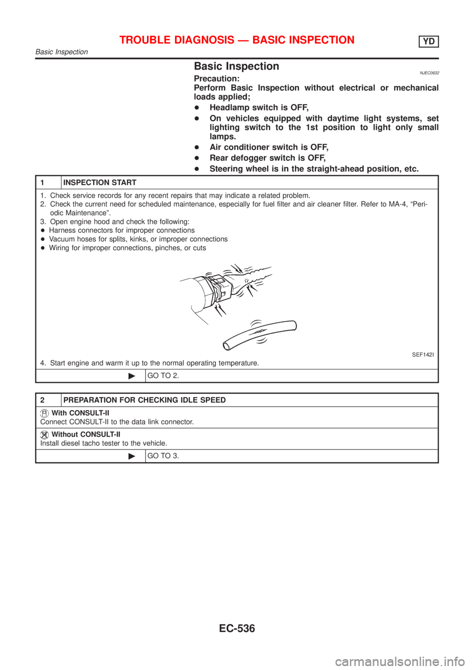
Basic InspectionNJEC0632Precaution:
Perform Basic Inspection without electrical or mechanical
loads applied;
+Headlamp switch is OFF,
+On vehicles equipped with daytime light systems, set
lighting switch to the 1st position to light only small
lamps.
+Air conditioner switch is OFF,
+Rear defogger switch is OFF,
+Steering wheel is in the straight-ahead position, etc.
1 INSPECTION START
1. Check service records for any recent repairs that may indicate a related problem.
2. Check the current need for scheduled maintenance, especially for fuel filter and air cleaner filter. Refer to MA-4, ªPeri-
odic Maintenanceº.
3. Open engine hood and check the following:
+Harness connectors for improper connections
+Vacuum hoses for splits, kinks, or improper connections
+Wiring for improper connections, pinches, or cuts
SEF142I
4. Start engine and warm it up to the normal operating temperature.
©GO TO 2.
2 PREPARATION FOR CHECKING IDLE SPEED
With CONSULT-II
Connect CONSULT-II to the data link connector.
Without CONSULT-II
Install diesel tacho tester to the vehicle.
©GO TO 3.
TROUBLE DIAGNOSIS Ð BASIC INSPECTIONYD
Basic Inspection
EC-536
Page 998 of 2493
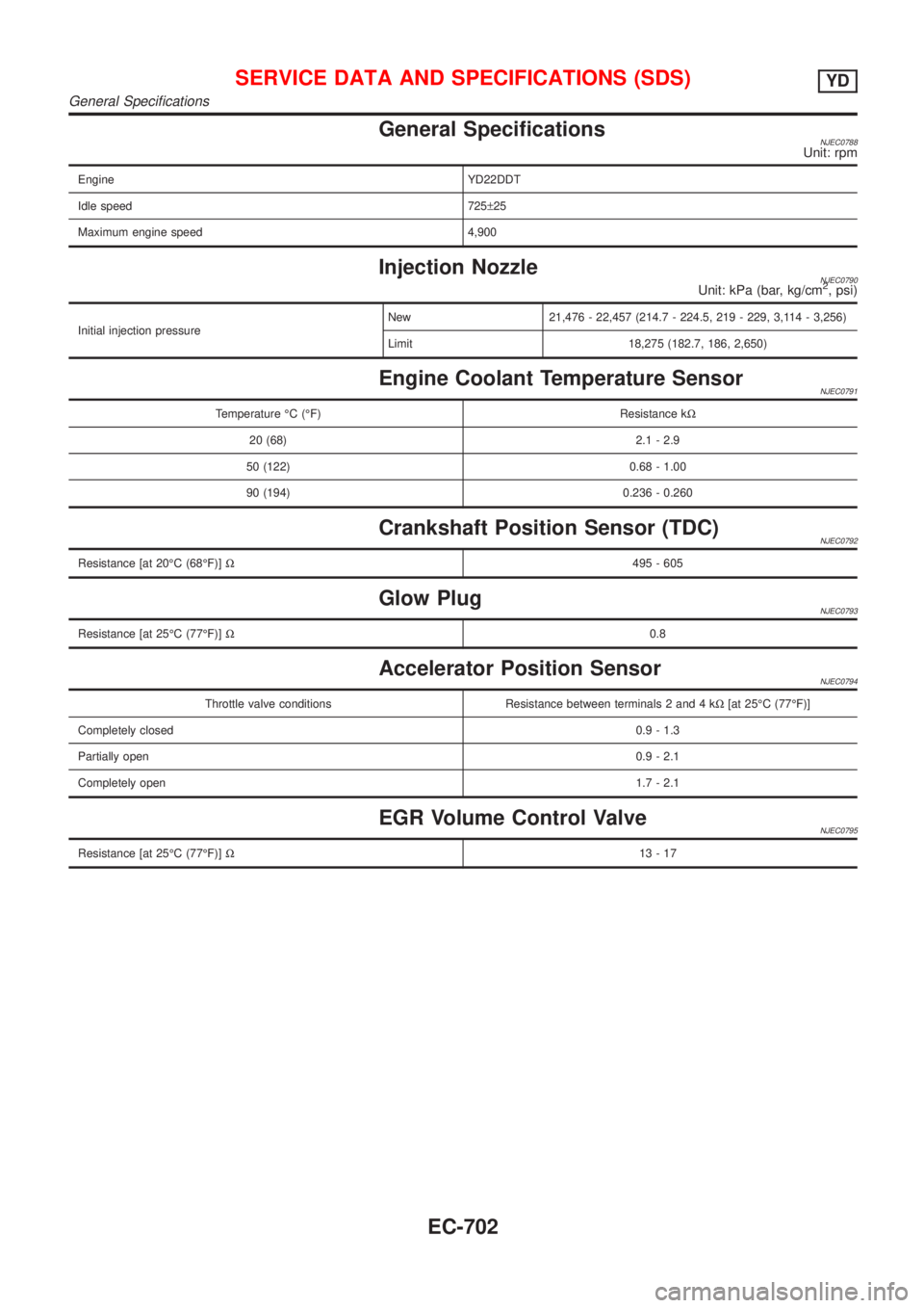
General SpecificationsNJEC0788Unit: rpm
Engine YD22DDT
Idle speed 725±25
Maximum engine speed 4,900
Injection NozzleNJEC0790Unit: kPa (bar, kg/cm2, psi)
Initial injection pressureNew 21,476 - 22,457 (214.7 - 224.5, 219 - 229, 3,114 - 3,256)
Limit 18,275 (182.7, 186, 2,650)
Engine Coolant Temperature SensorNJEC0791
Temperature ÉC (ÉF) Resistance kW
20 (68) 2.1 - 2.9
50 (122) 0.68 - 1.00
90 (194) 0.236 - 0.260
Crankshaft Position Sensor (TDC)NJEC0792
Resistance [at 20ÉC (68ÉF)]W495 - 605
Glow PlugNJEC0793
Resistance [at 25ÉC (77ÉF)]W0.8
Accelerator Position SensorNJEC0794
Throttle valve conditions Resistance between terminals 2 and 4 kW[at 25ÉC (77ÉF)]
Completely closed0.9 - 1.3
Partially open0.9 - 2.1
Completely open1.7 - 2.1
EGR Volume Control ValveNJEC0795
Resistance [at 25ÉC (77ÉF)]W13-17
SERVICE DATA AND SPECIFICATIONS (SDS)YD
General Specifications
EC-702
Page 999 of 2493
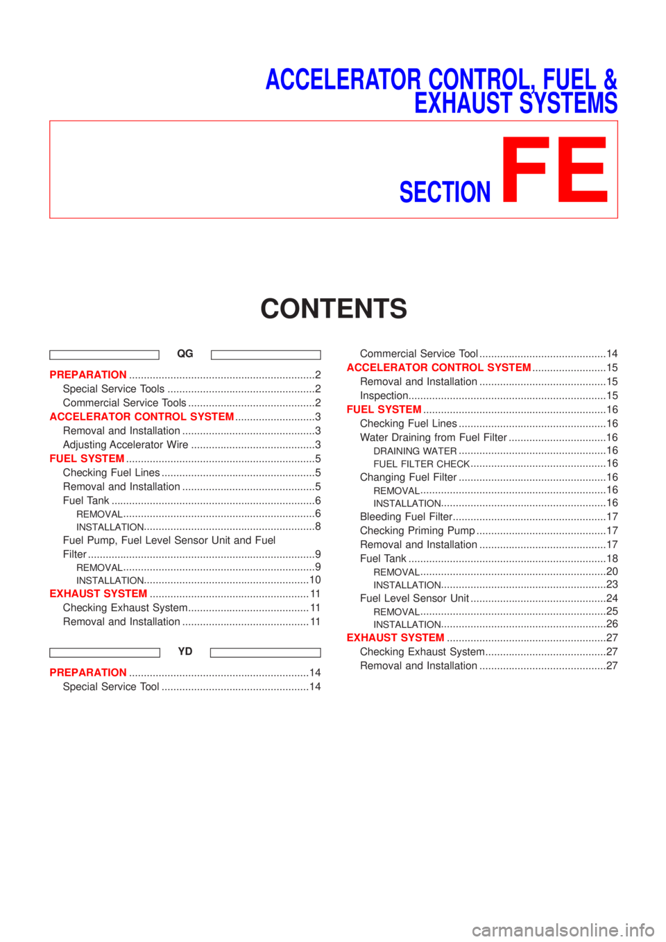
ACCELERATOR CONTROL, FUEL &
EXHAUST SYSTEMS
SECTION
FE
CONTENTS
QG
PREPARATION...............................................................2
Special Service Tools ..................................................2
Commercial Service Tools ...........................................2
ACCELERATOR CONTROL SYSTEM...........................3
Removal and Installation .............................................3
Adjusting Accelerator Wire ..........................................3
FUEL SYSTEM................................................................5
Checking Fuel Lines ....................................................5
Removal and Installation .............................................5
Fuel Tank .....................................................................6
REMOVAL.................................................................6
INSTALLATION..........................................................8
Fuel Pump, Fuel Level Sensor Unit and Fuel
Filter .............................................................................9
REMOVAL.................................................................9
INSTALLATION........................................................10
EXHAUST SYSTEM...................................................... 11
Checking Exhaust System......................................... 11
Removal and Installation ........................................... 11
YD
PREPARATION.............................................................14
Special Service Tool ..................................................14Commercial Service Tool ...........................................14
ACCELERATOR CONTROL SYSTEM.........................15
Removal and Installation ...........................................15
Inspection...................................................................15
FUEL SYSTEM..............................................................16
Checking Fuel Lines ..................................................16
Water Draining from Fuel Filter .................................16
DRAINING WATER..................................................16
FUEL FILTER CHECK..............................................16
Changing Fuel Filter ..................................................16
REMOVAL...............................................................16
INSTALLATION........................................................16
Bleeding Fuel Filter....................................................17
Checking Priming Pump ............................................17
Removal and Installation ...........................................17
Fuel Tank ...................................................................18
REMOVAL...............................................................20
INSTALLATION........................................................23
Fuel Level Sensor Unit ..............................................24
REMOVAL...............................................................25
INSTALLATION........................................................26
EXHAUST SYSTEM......................................................27
Checking Exhaust System.........................................27
Removal and Installation ...........................................27
Page 1000 of 2493
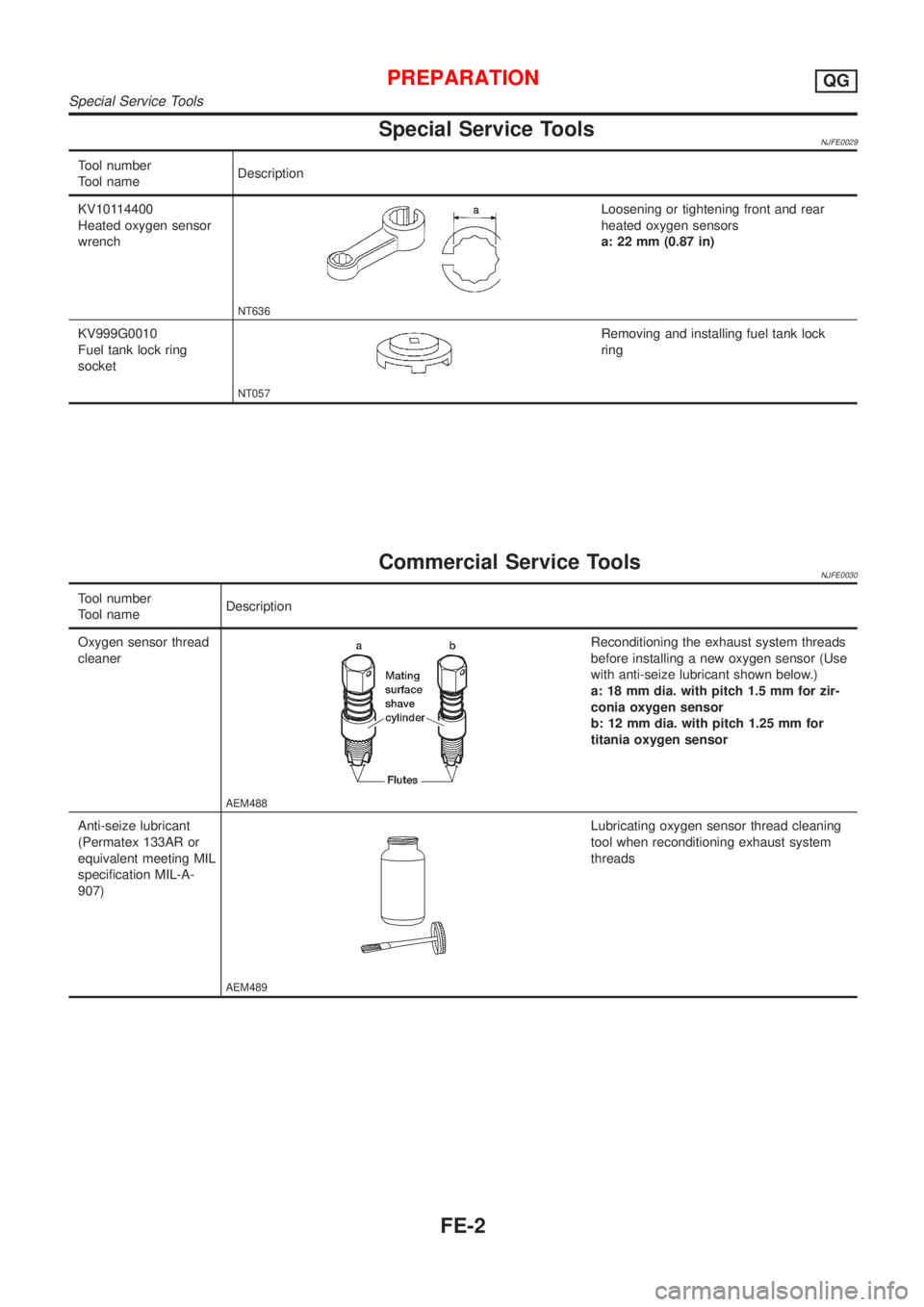
Special Service ToolsNJFE0029
Tool number
Tool nameDescription
KV10114400
Heated oxygen sensor
wrench
NT636
Loosening or tightening front and rear
heated oxygen sensors
a: 22 mm (0.87 in)
KV999G0010
Fuel tank lock ring
socket
NT057
Removing and installing fuel tank lock
ring
Commercial Service ToolsNJFE0030
Tool number
Tool nameDescription
Oxygen sensor thread
cleaner
AEM488
Reconditioning the exhaust system threads
before installing a new oxygen sensor (Use
with anti-seize lubricant shown below.)
a: 18 mm dia. with pitch 1.5 mm for zir-
conia oxygen sensor
b: 12 mm dia. with pitch 1.25 mm for
titania oxygen sensor
Anti-seize lubricant
(Permatex 133AR or
equivalent meeting MIL
specification MIL-A-
907)
AEM489
Lubricating oxygen sensor thread cleaning
tool when reconditioning exhaust system
threads
PREPARATIONQG
Special Service Tools
FE-2
Page 1012 of 2493
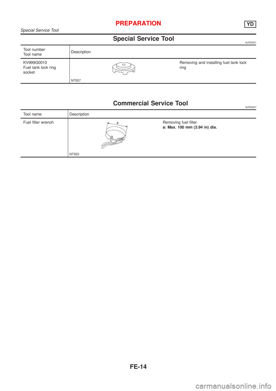
Special Service ToolNJFE0031
Tool number
Tool nameDescription
KV999G0010
Fuel tank lock ring
socket
NT057
Removing and installing fuel tank lock
ring
Commercial Service ToolNJFE0027
Tool name Description
Fuel filter wrench
NT553
Removing fuel filter
a: Max. 100 mm (3.94 in) dia.
PREPARATIONYD
Special Service Tool
FE-14
Page 1027 of 2493
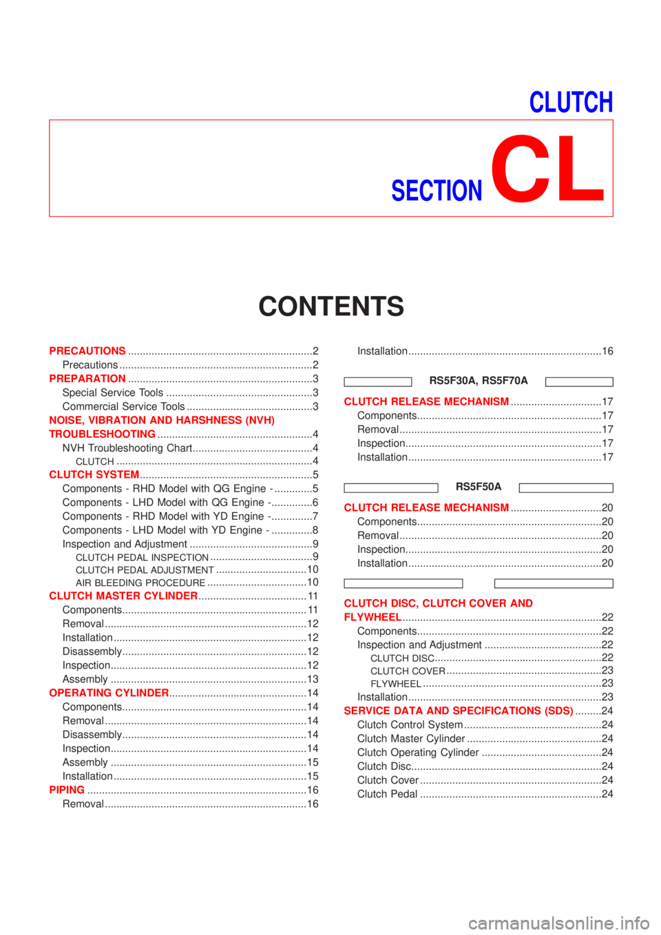
CLUTCH
SECTION
CL
CONTENTS
PRECAUTIONS...............................................................2
Precautions ..................................................................2
PREPARATION...............................................................3
Special Service Tools ..................................................3
Commercial Service Tools ...........................................3
NOISE, VIBRATION AND HARSHNESS (NVH)
TROUBLESHOOTING.....................................................4
NVH Troubleshooting Chart.........................................4
CLUTCH...................................................................4
CLUTCH SYSTEM...........................................................5
Components - RHD Model with QG Engine - .............5
Components - LHD Model with QG Engine -..............6
Components - RHD Model with YD Engine -..............7
Components - LHD Model with YD Engine - ..............8
Inspection and Adjustment ..........................................9
CLUTCH PEDAL INSPECTION...................................9
CLUTCH PEDAL ADJUSTMENT...............................10
AIR BLEEDING PROCEDURE..................................10
CLUTCH MASTER CYLINDER..................................... 11
Components............................................................... 11
Removal .....................................................................12
Installation ..................................................................12
Disassembly...............................................................12
Inspection...................................................................12
Assembly ...................................................................13
OPERATING CYLINDER...............................................14
Components...............................................................14
Removal .....................................................................14
Disassembly...............................................................14
Inspection...................................................................14
Assembly ...................................................................15
Installation ..................................................................15
PIPING...........................................................................16
Removal .....................................................................16Installation ..................................................................16
RS5F30A, RS5F70A
CLUTCH RELEASE MECHANISM...............................17
Components...............................................................17
Removal .....................................................................17
Inspection...................................................................17
Installation ..................................................................17
RS5F50A
CLUTCH RELEASE MECHANISM...............................20
Components...............................................................20
Removal .....................................................................20
Inspection...................................................................20
Installation ..................................................................20
CLUTCH DISC, CLUTCH COVER AND
FLYWHEEL....................................................................22
Components...............................................................22
Inspection and Adjustment ........................................22
CLUTCH DISC.........................................................22
CLUTCH COVER.....................................................23
FLYWHEEL.............................................................23
Installation ..................................................................23
SERVICE DATA AND SPECIFICATIONS (SDS).........24
Clutch Control System ...............................................24
Clutch Master Cylinder ..............................................24
Clutch Operating Cylinder .........................................24
Clutch Disc.................................................................24
Clutch Cover ..............................................................24
Clutch Pedal ..............................................................24