2001 MERCEDES-BENZ SLK-Class light
[x] Cancel search: lightPage 186 of 273

183 Malfunction and indicator lamps
Te ch n ica l
data Instruments
and controlsOperation DrivingInstrument
cluster displayPractical hints Car care Index Low engine coolant level warning lamp
With the key in steering lock position 2, the
warning lamp comes on. It should go out
when the engine is running.
If the warning lamp does not go out after starting the
engine, or if it comes on while driving, then the coolant
level has dropped below the required level. If no leaks
are noticeable and the engine temperature does not
increase, continue to drive to the nearest service station
and have coolant added to the coolant system, see
page 194.
The low engine coolant level warning light should not be
ignored. Extended driving with the light illuminated
may cause serious engine damage not covered by the
Mercedes-Benz Limited Warranty.
In cases of major or frequent minor coolant loss, have
the cooling system checked at your authorized
Mercedes-Benz Center as soon as possible.
Note:
Do not drive without coolant in the cooling system. The
engine will overheat causing major engine damage.Monitor the coolant temperature gauge while driving.
Low windshield and headlamp washer system fluid
level warning lamp
With the key in steering lock position 2, the
warning lamp comes on. It should go out
when the engine is running.
If the warning lamp does not go out after starting the
engine, or if it comes on while driving, the level of the
reservoir has dropped to approximately 1/3 of the total
volume. The reservoir should be refilled with MB
Windshield Washer Concentrate “S” and water (or
commercially available premixed windshield washer
solvent /antifreeze, depending on ambient temperature -
see page 195) at the next opportunity. The reservoir for
the windshield and headlamp washer systems is located
in the engine compartment.
Wa r n i n g !
Do not spill antifreeze on hot engine parts.
Antifreeze contains ethylene glycol which may
burn if it comes into contact with hot engine parts.
You can be seriously burned.
Page 187 of 273

184 Malfunction and indicator lamps
Te ch n ica l
data Instruments
and controlsOperation DrivingInstrument
cluster displayPractical hints Car care Index
Low engine oil level warning lamp
With the key in steering lock position 2, the
oil level warning lamp comes on. It should
go out immediately when the engine is
running.
If the warning lamp does not go out after starting the
engine, or comes on with the engine running and at
operating temperature, the engine oil level has dropped
to approximately the minimum mark on the dipstick.
When this occurs, the warning lamp will first come on
intermittently and then stay on if the oil level drops
further.
If no leaks are noted, continue to drive to the nearest
service station where the engine oil should be topped to
the “full” mark on the dipstick with an approved oil.
The low engine oil level warning light should not be
ignored. Extended driving with the light illuminated
could result in serious engine damage that is not
covered by the Mercedes-Benz Limited Warranty.
In addition to the warning lamp, the engine oil level
should be periodically checked with the dipstick, for
example during a fuel stop, or before a long trip, see
page 193.Charge indicator lamp
Should the charge indicator lamp fail to
come on prior to starting when the key is in
ste ering lock position 2 or sh ou ld it fa il to g o
out after starting or during operation, this indicates a
malfunction which must be repaired immediately at an
authorized Mercedes-Benz Center.
If t he charg e ind ica tor l amp comes on, or a l oss of power
steering assistance is noticeable while the engine is
running, this may indicate that one of the two poly-V-
belts has broken. Should this condition occur, the poly-
V-belt mu st be replac ed before continuing to operate t he
vehicle. Otherwise, the engine may overheat due to an
inoperative water pump which may result in damage to
the engine.
Do not continue to drive the vehicle with the charge
indicator lamp illuminated. Doing so could result in
serious engine damage that is not covered by the
Mercedes-Benz Limited Warranty.
Page 188 of 273

185 Malfunction and indicator lamps
Te ch n ica l
data Instruments
and controlsOperation DrivingInstrument
cluster displayPractical hints Car care Index Exterior lamp failure indicator lamp
With the key in steering lock position 2, an
indicator lamp comes on. It should go out
when the engine is running.
If the warning lamp does not go out after starting the
engine, or if it comes on while driving, this lamp
indicates a failure in the parking lamp, taillamp, stop
lamp, or low beam headlamp.
If an ex terior la mp fa il s, t he indicator la mp w ill c ome on
only when that lamp is switched on.
If a brake lamp fails, the lamp failure indicator will
come on when applying the brake and stays on until the
engine is turned off.
Note:
If additional lighting equipment is installed (e.g.
auxiliary headlamps etc.) be certain to connect into the
fuse before the failure indicator monitoring unit in
order to avoid damaging the system.Additional function indicator lamps
(in the odometer display)
FSS indicator (distance, Service A),
see page 75.
FSS indicator (distance, Service B)
see page 75.
FSS indicator (days, Service A), see page 75.
FSS indicator (days, Service B), see page 75.
Start lock-out malfunction, see page 24.
Malfunction and indicator lamp in the
center console
AIRBAG OFF indicator lamp
Passenger front airbag automatically
switched off, see page 53.
AIRBAGOFF
Page 192 of 273

189 Fuses
Te ch n ica l
data Instruments
and controlsOperation DrivingInstrument
cluster displayPractical hintsCar care Index 1Main fuse box in engine compartment (contains
fuses for interior consumers)
To gain access to the main fuse box (1), release
clamp (arrow), lift the fuse box cover up and
remove it.
To c lose t he ma in fu se box , engage ba ck end of cove r
and let front end snap into place.2Auxiliary fuse box to left of exterior lamp switch
(fuses for lights)
To gain access, turn locks (arrows) using a coin, and
remove cover.
1
P82.00-2050-26
P82.00-2064-26
2
Page 210 of 273

207 Tires, wheels
Te ch n ica l
data Instruments
and controlsOperation DrivingInstrument
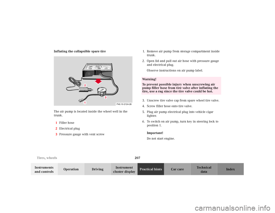
cluster displayPractical hintsCar care Index Inflating the collapsible spare tire
The air pump is located inside the wheel well in the
trunk.
1Filler hose
2Electrical plug
3Pressure gauge with vent screw1.Remove air pump from storage compartment inside
trunk.
2.Open lid and pull out air hose with pressure gauge
and electrical plug.
Observe instructions on air pump label.
3.Unscrew tire valve cap from spare wheel tire valve.
4.Screw filler hose onto tire valve.
5.Plug air pump electrical plug into vehicle cigar
lighter.
6.To switch on air pump, turn key in steering lock to
position 1.
Important!
Do not start engine.
P40.10-2124-26
1
0
45 6max. 6 min
A 170 584 01 38 AIR COMPRESSOR 23
Mercedes-Benz
2
3
2 1
1
2,5 bar
36 psi1
0 23
4
5
620PSI
BAR40
60
80
LUFTPRESSER12
12
3
Wa r n i n g !
To prevent possible injury when unscrewing air
pump filler hose from tire valve after inflating the
tire, use a rag since the tire valve could be hot.
Page 211 of 273

208 Tires, wheels
Te ch n ica l
data Instruments
and controlsOperation DrivingInstrument
cluster displayPractical hintsCar care Index
7.Operate air pump (approximately 5 minutes) until
pressure gauge displays 36 psi (2.5 bar).
8.To switch off air pump, turn key in steering lock to
position 0.
9.Unscrew filler hose from tire. Reinstall tire valve
cap.
Note:
Excessive tire air pressure should be released using the
vent screw.Storing spare wheel in wheel well
Deflate spare tire:
1.Unscrew valve stem removal tool, which is a part of
the valve cap, from tire valve.
2.Using the valve stem removal tool, open tire valve
slightly by turning the tire valve insert
counterclockwise to release air pressure.
3.When the tire air pressure has been released,
remove tire valve insert (protect it from dirt and
sand) using the previously removed tire valve cap.
4.Once all air is out of the tire, and the tire has
collapsed to its original shape, reinstall the tire
valve insert and valve cap.
Place spare wheel in wheel well and secure it with air
pump holder. Turn pump holder clockwise to its stop.
Page 212 of 273

209 Tires, wheels
Te ch n ica l
data Instruments
and controlsOperation DrivingInstrument
cluster displayPractical hintsCar care Index Tire inflation pressure
A table (see fuel filler f lap) lists the tire inflation
pressures specified for Mercedes-Benz recommended
tires as well as for the varying operating conditions.
Important!
Tire pressure changes by approximately 1.5 psi (0.1 bar)
per 18°F (10°C) of air temperature change. Keep this in
mind when checking tire pressure inside a garage -
especially in the winter.
Example:
If garage temperature = approximately +68°F (+20°C)
and ambient temperature = approximately +32°F (0°C)
then the adjusted air pressure = specified air pressure
+3psi (+0.2 bar).Tire pressures listed for light loads are minimum values
offering high driving comfort. Increased inflation
pressures for heavy loads produce favorable handling
characteristics with lighter loads and are perfectly
permissible. The ride of the vehicle, however, will
become somewhat harder.
Tire temperature and pressure increase with the vehicle
speed. Tire pressure should therefore only be checked
and corrected on cold tires. Correct tire pressure in
warm tires only if pressure has dropped below the
pressure listed in the table and the respective operating
conditions are taken into consideration.
An underinf lated tire due to a slow leak (e.g. due to a
nail in the tire) may cause damage such as tread
separation, bulging etc.. Regular tire pressure checks at
intervals of no more than 14 days are therefore
essential.
Page 216 of 273

213 Jump starting
Te ch n ica l
data Instruments
and controlsOperation DrivingInstrument
cluster displayPractical hintsCar care Index Proceed as follows:
1.Position the vehicle with the charged battery so that
the jumper cables will reach, but never let the
vehicles touch. Make sure the jumper cables do not
have loose or missing insulation.
2.On both vehicles:
•Turn off engine and all lights and accessories,
except hazard warning flashers or work lights.
•Apply parking brake and shift selector lever to
position “P” (manual transmission to Neutral).
Important!
3.Clamp one end of the first jumper cable to the
positive (+) terminal of the discharged battery and
the other end to the positive (+) terminal of the
charged battery. Make sure the cable clamps do not
touch any other metal parts.
4.Clamp one end of the second jumper cable to the
grounded negative (–) terminal of the charged
battery and the final connection to a grounded
heavy metal bracket in the engine compartment or
on the engine of the disabled vehicle.Important!
5.Start engine of the vehicle with the charged battery
and run at high idle. Make sure the cables are not
on or near pulleys, fans, or other parts that will
move when the engine is started. Allow the
discharged battery to charge for a few minutes. Start
engine of the disabled vehicle in the usual manner.
6.After the engine has started, remove jumper cables
by exactly reversing the above installation
sequence, starting with the last connection made
first. When removing each clamp, make sure that it
does not touch any other metal while the other end
is still attached.
Note:
If engine does not run after several unsuccessful
starting attempts, have it checked at the nearest
authorized Mercedes-Benz Center.
Excessive unburned fuel may damage the catalytic
converter.